Lighting Research Results

… - I can and do both.

However, during actual scanning, exposure is just controlled by the LED-source, which is driven by 12bit DACs (an old schematic can be found here).

The camera is just too slow to respond to sudden changes in exposure time. The LED-source reacts immediately.

The different exposure settings of the LED-source were independently calibrated to have identical whitebalances. The reason is that the intensity-current curves of the red, green and blue LEDs used in the lightsource are different. So they react differently with changing current. Furthermore, the wavelength of a LED changes sligthly with varying temperature/driving current.

I am not sure that this technique of changing exposure via the lightsource would work well with pure white-light LEDs, as you would loose the possibility of aligning the color temperature for the different exposure settings/driving current. But I have not looked into that.

Only during experiments I do vary the exposure time of the camera. During scanning, the exposure time is fixed to something like 1/32-1/25 seconds. Small adjustments of analog gain and digital gain are used make sure that the internal sprocket area, where full intensity of the lightsource is visible, is imaged in the darkest exposure to values not larger than 240-250 (in the 8bpp MJPEG). Thus, the exposure is set by reference to the lightsource, not the film. This ensures that the full tonal range of the film can be captured.

Hi to all. First, I would like to apologize to everyone about the English language (I use google translator) so that I do not understand everything. Maybe I wrote something wrong that I’m sorry about, but I’d like to send you my work. I think that there is absolutely everything about details in dark scenes, the only thing that worries me is the noise of the camera. Of course, I would limit the HDR, but unfortunately I do not have a camera that could scan 2 exposures at 24 fps in real time. I would like to show you but the only way is via Skype :frowning: I speak better than I write :slight_smile: I’m posting on the forum a link to a movie trailer I did. I would like to know your opinion. Thank you all very much.

2 Likes

(Hey cpixp, there is some rambling here but there is a question at the very end i would really love you to answered)

I’m am always amazed by other peoples expertise :slight_smile: it kind of seem like magic, I’m a mechanical minded individual while i have a background in automation and a fair understanding of electronics, lightning and photography go right over my head, so indulge me if i loose track of reality for a moment :stuck_out_tongue:

My set up will use stepper motors to drive the film, I’m using a Panasonic G8 to shoot the frames individually, originally i had intended to take 2 shots, one IR (to use and an IR mask to clean up dust and scratches) and a white light one, but after seeing what you have done I really want to use the idea of HDR, allot of the important film I have really poor exposure, either really dark or really bright, I had always assumed this could not be corrected for because to much exposure and white out to little and shadows are black holes.

However, because of the trade off my machine took early on I’m building a small form factor I do not have much room for advanced lighting.

I would prefer to use a single source white light at 4000k (I’m assuming that cold white light would be preferable)

Now would it be possible to use the Camera shutter using cameras external remote I/O hocked upp the Adriano to control the speed of the shutter for exposure, would this control be accurate enough to control the exposure.

If do you think it would be better to simply dim / brighten the light and would that get the same effect, or would the alteration of the light change the property of the light itself not just the brightness

Hey MrCapri,

I do not have a lot of expertise with consumer grade digital cameras, so the feedback I can give is rather modest.

A lot of people have used these types of cameras to digitize film, with some very good results - even by taking just a single capture per frame. For certain cameras there exists interface software which makes controlling them from a PC presumably rather straightforward.

I have never tried this route of using standard digital cameras because I could not figure out how to interface my existing cameras to the small Super-8 frame format. And I didn’t want to buy an extra camera for my film project.

Usually, these kind of cameras are rather slow in photomode. So some people use these cameras in videomode, but I am uncertain whether you can change exposure settings fast enough in this mode to be usable. That is actually a common problem with all cameras - you have a noticable delay from the time you are requesting a certain exposure to the time the camera actually has settled to this exposure.

In fact, I switched at one point from taking images with different exposure times to working with a fixed exposure time in the camera and realizing the different exposures needed for my technique with a adjustable light source. This improved the time for scanning a film noticably.

Exposure fusion of several differently exposed images is a more involved technique than simply taking a single image per frame. As shown above, you can get very similar results both way. I would suggest an evolutionary approach, starting with the simplest setup (a constant, bright light source with daylight characteristics and a good camera) and do some scans with your material. Most of the film scanners nowadays operate like this and good results are obtained this way.

Only if you are not satisfied with these results, I would incremently advance the setup. The specific way to do that depends to a large extend on your taste and the willingness to invest personal time and other things.

One big disadvantage of taking several images of a frame is the increased scanning time. The longest Super-8 film I have has a running time of 1.5 hours - this will take my scanner about 90 hours to digitize, or nearly 4 days. Of course, the scanner can run unattended, but occasionally I prefer to check if the machine hasn’t chewed up my film.

In addition, the exposure fusion is an expensive algorithm in terms of processing times as well. For 1200 x 900 px (my usual choice) it takes about 1 sec per frame, for the maximal resolution I am working with, currently 2880 x 2160 pixel, my not-so-slow-PC needs about 3.5 seconds per frame - so for the above mentioned 1.5 hour long film, you have to add an additional 4 days to finally get the digitized frames. If you reduce the number of exposures you use per frame, the times quoted reduce noticably. Even only 2 different exposures will get you somewhere.

If you are working with raw image captures, you would not even need to use exposure fusion at all, especially if your camera features 12bit or, even better, 14bit DAC-resolution. This is all a question of taste and priorities - where do you want to spend time and effort, what is the final end product (for me, it’s web content which I can share easily) and what kind of software/workflow you have at your disposal.

While I have not tried to use a white light source, I think the shift in color temperature is not too pronounced, especially if the LEDs are ment to be dimmable anyway. Furthermore, exposure fusion has the tendency of covering up small differences between the different exposures of a single frame. So yes, that would be my approach to try out, especially because it is much easier to control. Even an Ardunio can handle that fine (in my scanner, an Arduino Nano is driving the steppers, reading the tension sensors and adjusting the LED intensities. The Arduino gets its commands from a Raspberry Pi, which is handling the image captures, streaming the images and additional data to a PC which finally stores the images and metadata on a hard disk. That setup has some historical reasons; the bottleneck is the transfer of the images from the Raspberry Pi to the PC via LAN.)

Concerning the IR image to mask dust and scratches - it will be interesting to see how far one can push this. Personally, I simply clean the film before I scan it. And many scratches you can “hide” by using a very diffuse illumination source, specifically an integrating sphere. One point overlooked here quite often is that this only works as intended if the film is as close as possible to the output port of the sphere. Otherwise, this effect is much reduced.

First off, thanks you for responding whit all this information.

It’s given me a bit to think about, in regards to not needing exposure fusion if I’m working whit raw, I’m not sure what you mean like I said this is stuff I’m very basic whit how to work whit this stuff.

As for workflow, I have no super 8 film longer then at most 15 minutes long and my last attempts at scanning threw my flatbed where I could scan 30mm each time at almost 7 minutes per scan…

I did not scan many films, I don’t mind putting in the time as long as it works.

I got a Panasonic g80 on the cheap it’s a great camera and ones a stumbled across the idea of shooting whit a reverser ring i lost my mind for a moment at the revelation and then i stumbled across this forum and i was off to the races.

The information i have got here have made me constantly reevaluated my design and my thinking.

But what you showed me whit the “exposure fusion” completely changed everything, because some 8mm film I have, it’s shot in either VERY bright daytime, or at night causing a lot of problem. Getting much information out at a single amount of exposure.

I would apriciate any more information on who you controle the dimming of the LED’s i saw the Diagram you had of the 12 bit dac controler, but do you have any more in detail on how it’s connected up to the aurdino or the LED’s?

I got digital ice built in to my flatbed scanner and it’s noting short of magical, in my case it’s experimental and i’m not counting on it being able to work but i’m going to give it a try.

Thanks very much for everything.

Well, the DAC, an MCP4812 (10bit) shown in the schematics as well as the MCP4822 (12bit) I am currently using have an SPI-interface (marked SCK and SDI in the schematics). Any Arduino has some of its input/output-pins dedicated to a specific function. Specifically, with the Arduino Nano, the pin D13=SCK, the pin D11 = MOSI and the pin D10 = SS is of interest here. Have a look at this page for some further reference.

Normally, in the Arduino world, you connect an external IC either directly, via I2C or SPI. For a specific device, you also need a library in order to talk to the different registers of an IC for example. Usually, you are lucky and someone already did write an Arduino library. Than it’s easy sailing. You can find numerous examples at these pages here and otherwise.

Well, to illustrate the schematics a little bit in more detail: the MCP48?? gets a register set to a value between 0 to 4096 (12 bit version) or 0 to 2048 (10 bit version). This causes the DAC to output a certain voltage on its pin 8. This voltage is piped to the input of the operational amplifier (U1A)

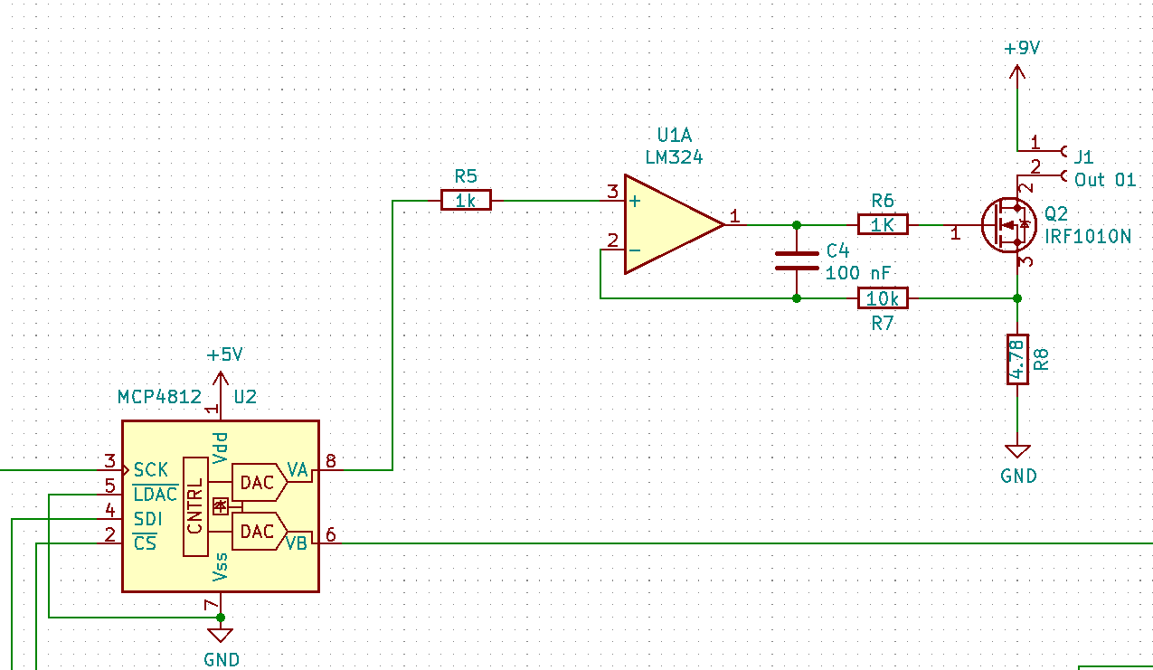
This unit is trying to keep its inputs 2 & 3 at the same voltage; it can only do this by opening more or less the IRF1010N (Q2) so that over the resistor R8 a sufficient voltage drop occurs. The current flows from the +9V via the connector J1, where the LED is connected, through transistor Q2 and resistor R8 to ground. That circuit is a simple voltage-to-current converter. C4 and R6 are a simplistic low-pass filter to avoid that the operational amplifier starts oscillating. As I mentioned earlier, a crude design with parts I found in my part bin. You can probably find better designs for programmable current sources on the internet.

One important point: there are basically two ways to dim a LED. The one used in dimmable LED-strips for example is PWM - pulse width modulation -, where high frequency constant current pulses are driving through the LED. The light intensity is controlled by varying the width of the pulses. That is a simple, cheap design - stay away from it for scanning purposes. You invite all kinds of trouble.

The design sketched above works by actually changing the current through the LED continously - this is more involved and more expensive. Mainly because you have to take care of large amounts of excess heat generated by the transistor (Q2 in the schematics) and the measuring resistor (R8). Both have to be quite beefy.

One last comment: like any analog film material, Super-8 film stock has a limited dynamic range. Material which was over-exposed during shooting too much will have burned-out highlights and there is no way to recover that lost information. On the other end of the scale, severely under-exposed material will show very little structure in dark shadows, with a lot of noise. This is also very difficult to recover, and at a certain point, everything will be just a structureless dark noise blob. However, if you can see structure in the highlights and shadows in a normal projection, chances are that you will be able to recover this electronically.

@MrCapri, if you can integrate a Raspberry Pi into your build, you might want to check out gPhoto2 for controlling your camera. This allows you to control most DSLR and DSLM type cameras programatically from a Linux machine (the Pi included). Depending on the camera you use, you can control more or less functions, but the basics (such as releasing the shutter or setting the shutter speed/aperture) work on most models. All you need in hardware is your camera’s USB cable plugged into the Pi. Just check for what functions are compatible with your camera. There is also loads of beginner’s tutorials around the internet, so you should easily be able to get started.

@cpixip, nice explanation of the circuit. I initially wanted to do my lighting setup without any current control and only use the exposure time of the camera. Since I want to use a mono camera and combine three (RGB) channels it might be good enough. But then again it is much more flexible and ‘fun’ to have some analog current control. Although I would not want to use a very large range since the color frequency will shift somewhat in the low ranges.
Here is a link link describing the effect.

@cpixip , Thank you agine, we can see struckturs and if i over expose i can see what is in the dark patches and so forth.

These films will never be perfect or even some al all recoverabul but any chanse to get anything out of them is going to be an amazing opertunity.

For exampel one film is of out of a window of a cargo plane at dawn or dusk you can see there is alot of stuff but its way to dark

@jankaiser I have looked in too gphoto2, unfortunaly the Lumix g80/g85 is not supported, while some peopel have got the shutter to work, adding a Rpi simply to run the shutter is alittle overkill, if i can get the same result from adjusting the LED brightness and that would also enable faster shutter speed to be used.

… you are absolutely right, this effect is there and I remarked above that if you are utilizing white light LEDs, you have no chance to counteract it. However, I am using separate red, green and blue LEDs, and the 5 different illumination settings are independently calibrated to the same color temperature.

There is actually another reason one has to go through such an individual calibration of every illumination setting: the current-intensity curves of the LEDs used are very different, so doubling the current on, say, the red LED is not equivalent to doubling the current of the green or blue LED. The imbalance caused by this is actually much stronger than the shift of the main peak of a LED by changing the driving current.

To give an example - the darkest illumination level I am using has the calibrated setting red = 113, green = 126 and blue = 52 (the full range spans from 0 to 4095). The brightest illumination level has the settings red = 2146, green = 4095 and blue = 889. So while the red and green components have nearly similar amplitudes at the lowest illumination level, the red component is only about one half of the green component at the highest illumination level. This is mainly caused by the different current-intensity curves of the LEDs, which are in turn caused by the different materials used for the different wavelengths.

I did actually tests where the color balance of some of the illumination levels was off (not much) - depending on the settings of the exposure fusion algorithm this was barely noticable. The reason is that exposure fusion tends to average for each pixel over several exposures. This reduces any deviation which is happening, including color shifts and image noise.

The current image capture pipeline is tuned to capturing standard Super-8 material. As I know from experiments, the Raspberry HQCam is assuming “daylight setting” in its processing pipeline (that is independent whether you use the standard one, the BroadCom stack, or the new one, the libcamera stack). So the illumination is set to deliver just that - light which mimics “daylight” as close as possible.

This actually ensures also that the raw camera channels are utilizing the maximal dynamic range possible, which was one of the goals of the design.

Setting manual whitebalance will also result in choosing a fixed ccm-matrix by the image processing pipeline while creating the MJPEG-images I am using later for exposure fusion. At this point in time, I do not know whether other steps in the image pipeline are changing colors as well (the automatic lens shading algorithm might be a candidate), but from test I would judge such influence is minor (if present at all).

I am still working on a good way to scan Super-8 material with a severe color cast, for example film which was exposed without setting the daylight filter of the camera correctly. It is possible to scan such material by changing the whitebalance settings of the camera (keeping all other settings fixed), but this approach lowers the amplitudes available in the raw camera channels, lowering in turn the dynamical range available for processing. It would be better to keep the whitebalance settings at “daylight” and adjust the light source to the material at hand - I am currently looking into whether this is possible.

2 Likes

I am always suprised of the internets ability to find likeminded people, even though I grew up with it.
I plan on building a machine to scan cut still film and am researching of how to design the lightsource for the integrating sphere. Someone at labsphere recommended a sphere with a 25-30mm diameter for backlighting a 6*7 negative.
I plan on going with RGB Leds but have problems choosing a good option.
The datasheets of most multicolor chip LEDs often show relatively powerful lumen outputs for red and green, while the blue LED is often weak.
Wouldn’t a good lightsource need to provide continous lumen output throughout the spectrum?
I don’t understannd why these LEDs e.g. https://www.mouser.de/datasheet/2/228/LED_2520Engin_Datasheet_LuxiGen_LZC-03MA07_rev1.8_-1531871.pdf have such odd balancing of R,G, B (although I now that blue LEDs are more complicated in their design)
Yes, you could always gain the individual channels to match, but that would mean pulling up noise as well. Wouldn’t it be desireable to have equal lumen output for R,G,B as the quatum efficiency of monochrome sensors seem to be relatively equal.
What approx. lumen output per channel would you recommend for a sphere with a 20cm diameter?

This is the quantum efficiency of a modern mono sensor:
BFS-PGE-122S6M_624x312
And it’s color version:
BFS-PGE-122S6C_624x312
And here are the spectra of some daylight situations:

So you see the blue light wavelenght is a little bit lower (in dB), I think that is the reason of the combination. But I might be wrong!! Was also wondering what would be the best bnrightness for the blue leds’s since as you see the quantum efficiency is lower for the blue colors, and you might compensate for it.

I ahve been looking around for a lightsource to use, and wanted to ask opinion from more knowlegabul.

I’m looking for an off the shelf Dimmabul LED driver, and i have found what seem to be two difrent ones.

Now maybe i’m overthinking this and building my own is not as complicated as it seem, but this would cut down on another project i would have to start up.

If any one had the time to take a look if you think this would be a workabul alternativ, i would apriciate it.

eldoLED V-Strip 4-Channel Light Controller, 12 28 V dc

https://se.rs-online.com/web/p/led-lighting-controllers/6972967/

eldoLED L-Dot 4-Channel Light Controller, 24 32 V dc

… from the datasheets it is not possible to interfere the actual technology these drivers are using. Judging from the formfactor of the PCBs, it’s PWM-based. That is exactly the technology I wanted to stay away in my design. The LEDs are driven in this design by high-frequency pulses and dimming is achieved by varying the pulse width. So potentially, you have an interaction between the high-frequency lightpulses and the camera sensor which can lead to flicker effects if you use very short exposure times. I have seen professional video footage of stage acts which suffer from this.

Presumably, these LED guys know what they are doing and use a high enough PWM frequency so that this is not an issue for the usual exposure times. Most of the TV-shows have no issues with that. For my setup with exposure times of around 1/32 seconds, it is certainly not an issue, but going down to exposure times of 1/4000 or lower (if you want to freeze a non-stopping film strip) I am not so sure. Maybe someone else does have experience here?

1 Like

Thanks for cheaking it out reavy apiciate it, looks like no shotcuts for me.

… not necessarily. The usefulness of PWM-based LED-controllers is related to the frequency they are operating on. With a sufficiently high frequency, you won’t run into any problems. I simply do not know whether this is an issue or not.

Again, maybe someone else on the forum has experience on the usefulness of PWM-based LED-controllers in scanning applications.

Here’s an example where you can see flicker in stage lighting caused by PWM, and here’s a discussion about color shifts under PWM. Whether this has any relevance with respect to film scanning, I can not tell you. You probably just have to try it out.

@cpixip Thanks, i cant tell you how much i apriciate you taking the time to respond.

For right now i’m more looking for a simpel/cheap and easy way to try out these ideas, i think i will eventualy build a system like you described, but whit a singel LED.

But for now i’m more trying to get something together to experiment whit, I realise i actuly do have some LED strips laying around and i thihnk the aurdion can controle them directly.

Last year I actually bought the very last LED and Board that Frank Vine made for consumers. He only makes the LED and control systems for his commercial customers now.
As he describes here, he adjusts the duration of the 3 color LEDs for exposure and color balance. It uses his own proprietary software written with ActiveDcam from A&B Software.

I suspect that @cpixip could merely glance at this and determine how to write open source software for it!

@cpixip if you have an interest in reverse engineering that unit and its software, I’d be happy to support that effort.

… well, Frank Vine’s color control system is quite powerful. It switches the LEDs on during a short time when the camera takes the frame. Otherwise, the LEDs are off. So it’s a pulsed system, and as Frank remarks, “not suitable for use with rolling shutter cameras.” The Raspi HQCam is a rolling shutter camera, among others.

With a help of a FET, a microprocessor can switch on-off any LED quite precise. That is what is used in Frank’s system for exposure control. He even describes the electronics used at his page.

The system monitors the temperature of the LEDs and applies a temperature correction. I have my doubts that something like this will have noticable effects in this setup, as the switching of the LEDs leads to a continous temparature change during operation. Maybe it’s operating on a time-averaged setting.

The special twist of this system is that the image from the camera is analyzed and the LEDs are driven in such a way that the maximum dynamical range of the camera is used in every color channel. In this way quantization effects and noise are reduced. Of course, the frames captured will have a weird color balance which needs to be corrected in the post.

Well, if you design a system from scratch, you have many options available. Here’s my take on a illumination system:

  1. Will your film be running continously and you need to freeze the frame by flashing? If so, you will need a global shutter camera and a LED system which you can trigger fast and reliably. Simpler and cheaper is to use rolling shutter cameras and a continously operating illumination system. For this to work, you obviously need to stop the film during frame capturing.

  2. Do you want to scan film material which is severly under-exposed or even off-color (maybe forgot to switch on the daylight-filter, for example). If so, you will need an adjustable light source with a sufficient power reserve. On the other hand, a lot of people have obtained resonable results with a simple white-light LED, compensating with the camera’s whitebalance and exposure settings. Of course, in doing so, you will not be able to use the full dynamic range of your camera.

  3. Depending on the film material, your camera might not have the power to resolve the full dynamic range of the film. To optimize here, you have two options: one, as noted above, is to use your cameras whitebalance and exposure settings. The other is to employ an adjustable light source to maximize results, while keeping the camera settings to fixed values. The later option has the advantage that LED-light sources can be switched usually much faster than usual cameras. You can basically vary the current of the LED (not much used), or the duration the LED is switched “on” (PWM - defacto-standard nowadays, big advantage in heat dissipation, among other things). If using PWM, you need to make sure that the switching is done with a high enough frequency in order not to run into beat patterns or flicker problems.

  4. Film material which is/was used for projection is tuned to the spectrum of bulbs, which is very different from the spectrum a LED light source produces. Actually, there’s even a difference spectrum-wise between a light source composed of red, green and blue LEDs and a “normal” white-light LED. In any case, there is also the spectral filter characteristic of your film, which will vary between different film stock, and the spectral sensitivity of your camera. All these spectral characteristics interact and make it kind of difficult to arrive at an optimizal light source. And an optimal LED combination for Kodachrome might not be perfect for Agfachrome or Fuji stock. It’s probably easier to tune all that in post production.

  5. What you can optimize is the dynamic range your camera is operating on. Here’s my take on this: all film stock I have encountered (Super-8 home movies) have occationally some part of the frame which is so heavily overexposed that it is pure white, i.e., the pure light from the illumination source is shining through. Clearly, this gives you the upper range of intensities you not want to be clipped by your camera. Now, consumer-grade cameras (including the Raspi HQCam) are somewhat optimized for daylight operations. “Daylight” corresponds to certain white balance settings of the camera, and it is that setting one should use in manual whitebalance mode. If you do so, these clear patches in your film material probably won’t be really white (actually, you have to check this with an exposure setting low enough so that these light patches turn grey, in order to stay away from clipping effects). If you now tune your light source so that these patches appear grey again, you are going to have nearly equal amplitudes in the red, green and blue color channels of your camera. Not perfect, but close enough in my experience.

  6. Film will have scratches. Some are minor and can be handled by appropriate light source design. Basically, you want to shine light through the film frame from every angle possible. There’s only one design which does that perfectly, and that is an integrating sphere. However, for this to work as intended, you need to place the film as close as possible to the port hole of the sphere. Any further distance reduces the incident angle of the illumination, reducing in turn the desired effect.

Well Matthew, I probably would not really know what to reverse-engineer…

The basic operation of the unit is quite well described at Frank’s webpage, even the circuit diagram he’s using is there. From what I understand the system is basically a hardware-based unit with dials for adjusting the red, green, blue and an additional “IR”-channel.

The temperature-compensation Frank is mentioning is quite interesting, but highly probable tied to the specific LEDs he’s using. Since he’s driving all LEDs of a channel in series, variations of the LEDs respondance to a certain current (which happens with real LEDs) would not be covered by such a temperature compensation. Also, at least in my experience, temperature drift of LEDs has barely a noticable effect in real captures (given, I have done only a few experiments about this and never looked back - maybe I should revisit that theme again…)

Well, continueing: presumably one additional microprocessor in Frank’s unit is acting as a kind of sequencer, receiving a trigger input itself and than triggering in turn the different LEDs and the camera, for example to realize separate red, green and blue captures of a given frame with a monochrome camera. He’s using PICs for that, I would certainly use some Arduino-clone nowadays.

The hardware unit features for every channel a simple constant current source, plus a simple FET-switch for the realizing the pulse timing. The LED current seems not to be adjustable - for a redesign, that would be certainly an option to consider adding. If so, you could use the unit in both ways, either in varying current mode, or in varying exposure time mode. Or even in a combination…

The software he’s describing seems to be actually split in two parts - one software is a capture software for firewire-cameras. Nice, but, in sense, firewire probably had it’s days. New interfaces (USB3, CameraLink, GigE and CSI) offer much higher transfer rates and in turn potentially higher scan resolutions.

The other piece of software he’s decribing is a application which is just a software recreation of the real dial hardware, enabling you to turn the knob on your screen without turning to the real hardware. The only thing I can imagine important here is that watching the real-time histogram (of his capture software) with selectable region-of-interest can be combined with the on-screen dials to optimize the light source for a given scan (for using the full dynamic range in all color channels, for example).

4 Likes