@matthewepler - that looks nice. One word of caution: a good working integrating sphere does not need a diffusor on its exit port.
1 Like
Ah, good point! Thanks for reminding me @cpixip. Would you make any changes to the tube design?
@matthewepler: I am afraid that I can not really comment on this. The geometry will be heavily influenced by the spread of the LED-light (angular distribution) and the choice of the material at the inner surface of the tube. Also, the diffusing properties of the diffusor will play a role in this.
All good. Guess we’ll just have to build it and see how it goes.
This is very true - I tested this to get a consistent measure of the light loss penalty of having one in the chain (since it’s a requirement for the direct-drive model).
@junker - I know, the hot spot is egregious for that level of diffusion! I wanted to test this on a large aperture because I had a good experience using a similar design (although for an 8mm gate with the same diffusing material) and I suspected that it might not hold up for a 35mm gate, but I didn’t know how bad it might or might not be. Good thing for testing!
-
It’s not a terribly big deal, although it would absolutely require baffles to be added to the interior of the sphere. This would precipitate some more testing depending on the model of LED being used, generally enlarging the sphere in this case would be advisable.
-
LED control can be done from the shield, but in the case of the Yuji LED that I tested, it really likes to be driven at around 19V, which would require a dedicated power supply. Other high-output white LEDs would be similar (i.e. they probably won’t run off the ~5V available). A confounding factor here is that most LEDs of sufficient brightness will likely require some kind of cooling as well, so having the LED separate from the shield (i.e. leaving room for a cooling apparatus) is beneficial.
-
Which leads to your second drawing which might be the ideal hybrid of both designs (the version on the left) - it positions the LED so that it can be cooled and accessed easily, and based on my experience with the integrating sphere model and the direct drive model I believe it would provide a sufficiently bright and even field. Absolutely worth testing! (I’d be very curious to do all three measurements- no diff/ground glass/white diff - not being a sphere I think it would still need some diffusion, but I suspect we would be able to get away with something like the ground glass (brighter!))
Foamcore would work for prototyping but I’d be hesitant to use it in any kind of production environment  For testing I think we should keep up with the Barium Sulfate coating process - BaSO4 was picked for this kind of application specifically because of its history as THE reference standard material. The diffuse reflectance characteristics are well known and pure white latex paint is known to have lower reflectance. A mix of the two for durability and ease of application is still ideal, I think!
I’m also going to order a true white PLA filament for comparison. @johnarthurkelly I can ship the print to you if you DM me your address.
1 Like
FWIW, there are two points I’d like to make regarding the research and the comments in this thread:
-
The research paper indicated that there is not much difference between a full spectrum white LED vs. individually controlled LEDs. While that may be true, the latter does offer the additional benefit of allowing for scene level color correction.
-
For diffusing material, I have successfully used the diffusion material from junked flat screen monitors and TV sets. The larger sets have thicker plastic that can be cut with a jigsaw (a trick is to cover both sides with clear plastic packing tape which is a way to lubricate the blade in order to make a nice cut). Smaller sets have thin flexible sheeting. Either way, it’s a great way to obtain true diffusion material. Recycling centers and curbside are convenient sources of flat screen TV’s and computer monitors. Caution should be used if the backlight is the older fluorescent type (as opposed to LED) because the thin tubes easily break and contain mercury (a toxic substance even in small amounts). So as a precaution, please pay attention to that.
Greg
Hi Greg - It’s not that I found there to be much of a difference between the two, theoretically they can be perceptually identical to the human eye, but the downstream requirements of the system are dramatically different for taking best advantage of each design. Scene-level color correction is a good thing to be able to do, but it definitely adds significant complexity overall where we can cover most situations with the more simple option.
WRT the diffuser material, there is a lot of variation in the kinds used in flat panel displays (partially dependent on backlight/edge-light design). I would be cautious about their spectral properties and overall diffusing power - certainly something to evaluate. The options used in the test allowed us to specifically compare a neutral, diffuse surface (ground glass) vs a diffuse material and evaluate the brightness attenuation penalty in each.
1 Like
Hi John - Thanks for your clarifications. No doubt there is a complexity trade-off between the two approaches and my point was probably an obvious one. Actually, I was unaware that full spectrum white LEDs exist and so that it an option that should be considered. I don’t recall that it has been mentioned before in the discussions here (unless I missed it), so I’m glad to see it being presented in your paper. In regards to the diffusion material, that was more in response to using poster board since it is specifically designed for light diffusion. Of course testing the properties would be the best way to discover the true properties. I thought it was worth suggesting since so many solutions I’ve come across use “found objects” such as ping pong balls and ordinary paper. Thanks again for your detailed research!
1 Like
Hi Everyone - With @matthewepler’s help on some quarantine 3D printing I tested a model based on the Right-Angle Diffuser Box design:

(shown here as two halves for printing purposes)
Two versions of this were made, one printed with White PLA and one with Black PLA. I tested the White PLA model without any extra coating, and then both models after applying the same Barium Sulfate/Latex paint diffuse reflective coating that I used in testing the earlier designs in this thread. I performed the same measurements on these variations using the same White LED and driver from the earlier tests. These are the results:
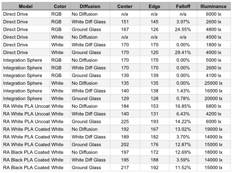
The RA Diffuser Box model generally underperforms the Integration Sphere in both measured falloff and illuminance, however it is notably better than the earlier Direct Drive model. The uncoated White PLA performs quite poorly compared to the coated PLA.
I believe the falloff observed in this model is mainly the result of the LED being aimed directly at the “45 degree” diffuse reflector and causing a hot spot on the part of the reflector closest to the LED. Also the length of the tube between the reflector and the aperture likely caused some of the measured falloff. The next iteration of this design will place the LED such that the light will have to perform at least one bounce before reaching the final reflective surface as well as a shorter distance from the final reflective surface and the aperture.
2 Likes
Thanks for publishing these results in such an easy to understand format @johnarthurkelly. Really useful. So the integrating sphere remains the design to beat!
If I’m reading it correctly, it seems like the coated white performs slightly better than the coated black. Is that right? I assume this would apply to the sphere as well?
Perhaps ever so slightly, although that may be within the margin of error for the light meter. It could also be the result of variations in the thickness of the coating - I coated each version the same number of times but since I was applying the coating with a brush it may have some unevenness that I can’t see by eye. I’ve been considering using a small paint sprayer (hobbyist size for models and the like) that might help even out the coats.
1 Like
I found on eBay 6” round aluminum cake pans (To make basketball cakes) which based on my math should work for an infinite sphere (port 1.75” x 1.25”).
As I am transferring a 35mm positive print which is in good shape and color corrected, I elected to try and use just white LEDs as opposed to doing an RGB light source.
My question is what particular LED (hope to use only 3) would be appropriate to use?
My first thought was to use a bias light strip but when it came and wasn’t ready to test, I put on our TV and fell in love with effect. It may still be a candidate but figured three separate LEDs might be better.
Appreciate any suggestions on what to buy.
@brian where you able to read the PDF of John’s research? It has links to the LEDs he used.
@matthewepler, yes I did look at @johnarthurkelly PDF and appreciate his time to do the research.
John, I am planning on using three of the spec’d out white LEDs, YUJILEDSTM VTC 135L COB and figured the 5600K would give best results, I do note you used the 3200K what is your opinion on going daylight, which it seems is closer to to a projector’s ARC/Xenon output (I am transferring to start from a projection print)?
2nd question, how many white LED’s did you use? I note they are sold in packs of 5, I was working toward using 3, similar to your idea with the RGB LED’s but now wonder if that would be over kill? (although somehow I can’t see having ‘too much’ light, just makes the ƒ stop a bit higher and may solve focus issues.
I was going to try to getaway from using a ‘gate’ as such figuring if I had enough light to use a fast shutter speed and a lens set up with enough depth of field I could just keep the film strip tight between a pair of rollers and let it flutter a bit without issue. Your note however on how the light falls off from the Sphere now has me thinking I need something to hold the film near the light source w/o damage.
Thanks
Brian
PS the dc/dc buck you sourced is no longer available on Amazon. Once I determine how many LED’s to use, I will look to see what other substitutions might be found.
1 Like
You should be fine going with the 5600K version if you’re working with projection prints. One caution I would advise is that these particular Yuji LED’s do get warm, so giving them proper cooling and also letting their temp stabilize for a few minutes after startup should keep your system running consistently well for longer scans.
For my 8mm build I’m just using one LED right now - the second version of the machine (I’d have built it during this quarantine but my 3D printer was locked up in my office) will have at least two. I’ve been poking away at a revision to the design of the Right Angle diffuser above that could be adapted for use on a small setup like my scanner or a larger 35mm machine. The only caution with using more is the proper heat dissipation. Up to a point you can certainly run brighter with the limits being either the damage threshold of the film itself or the upper exposure range of the imager. Right now I’m not wide open on my optics but I also could stand to use more light and ever so slightly increase the depth of field to accommodate film that might not be totally planar. (My current gate design doesn’t fully enforce film flatness when something like a rough splice passes through the gate. I could do it but then I need some lower-friction materials.) As you suspect, with 35, you should be totally fine with that much light and even possibly more.
To go “gateless” you’ll definitely want a lot of light - so it’s good that you’re working with projection prints. Your film speed through the machine might also be limited by the effective max shutter speed of the imager as well, so that’s good to spec out. Going through all of this gave me a real good appreciation for the engineering behind commercial scanners that can do 24fps or faster at even modest resolutions!
The dc/dc buck converters for the LED’s are all pretty much the same (you can get them on Amazon, eBay and I’m pretty sure Mouser et al.), so long as you have the kind that can be current limited. I initially tested using my bench top power supply, but I eventually needed to power more things at different voltages simultaneously. You can get them with or without a display, if you get them without a display make sure you’re carefully setting/checking the current limit with your multimeter before using them 
1 Like
John, hanks for the info! My plan is to mount the LED on a machined aluminum holder (when you have access to machine tools, everything needs to generate chips) and that in turn mounted to a heat sink from an old computer processor. As my sphere is spun aluminum, it shouldn’t be an issue. I will keep your note in mind and be sure to monitor the heat at the chip mount once running.
One thought I did have, to avoid cutting a circle in the aluminum and wood base to fit the sphere and likely making cooling easier, was to mount the sphere with the port on the bottom and use an angled mirror but based on your research and others it seems you want to get the film as close to the port as possible. Using a mirror would probably make the light path 6-8 times as long. I think I will move forward with using only two LED’s to start and take some meter readings once it’s working.
Hopefully you’ll be back in your office and can start printing again.
Cheers
Brian
John, quick question on how you mounted and made the power connections onto the LEDs? At $25 per chip would like to avoid trial and error. It seems for best cooling they need a broad and secure connection to the heat sink. Appreciate your (or anyone else’s) input.
Ah, yes, that they do! I very carefully drilled and tapped the plate on my heatsink to accept two very small bolts that could pin down the corners of the led chip opposite of the solder pads. Since the solder pads are not very big, I soldered on two short leads that I could then splice onto some thicker-gauge wires more appropriate for the application. To be honest - I didn’t have a very good iron at the time and the tip was not in great shape so it was a difficult exercise, but it worked.
I’m sorry I seemed to miss the notification on the last post! While I’d say the general rule would be to get the film as close as possible, if the light from the source is well-collimated (but also uniform in intensity) then you shouldn’t have any trouble throwing it further away. I’d like to experiment with condensing optics for this purpose soon!
1 Like