No programming, really. It’s just faster. PLCs are meant for programming repeatable actions, so we will be setting these things up to do simple tasks like “go to X frame” or “advance one frame” – stuff like that. The Velocio PLCs are unique in that they don’t require you to use ladder logic, which is incredibly weird unless you’ve been using it forever. They basically provide a simple flowchart interface to build state machines, and the various controllers (which are tiny little pucks) can be networked together. So we can have one for just the steppers and torque motors and one for the motors that operate the camera/lens platform. Communication is over serial with modbus, so it’s easy to integrate into a desktop application
It could be done in the Arduino, and that was the original plan, but time constraints got the best of us, and this was a simple way out that didn’t cost that much.
I’d have to talk to the engineer who built these. The LEDs were selected based on the frequency response of the camera, but they’re a fairly generic COB form factor, so changing them out if there’s a new camera that requires different lamps. We will be using filters as well to really fine-tune it. We’re doing sequential RGB with a monochrome camera, and we’re reusing the cintel lamp house enclosure (which is very roomy - about 18" square by 6" deep), so we have lots of room to play in.
The Torque motors are these: 5TK20GN-AW2U / 5GN9SA 20 W (1/38 HP) AC Torque Motor (9:1 Gear Ratio) (Single-Phase 110/115 VAC) – the way they work is that they’re not meant to spin freely for a long time. They’re designed to hold something in place. Imagine two torque motors each with a reel on it. There’s film going from feed to takeup. The motors are pulling against each other, holding the film in place. If you move the film to the right (with very little effort), it holds there. If you move it to left, it holds there. They’re not meant to transport the film, just hold it in place. The capstan, which is just a stepper with a built in encoder and a matching driver, is what pushes and pulls the film through.
I was skeptical of this setup myself when I did the imagica, but it’s so simple I don’t understand why more scanners don’t do this. Of course, you do need to have basic sensors in place to shut the motors down, say if the film breaks or something, otherwise they’ll both start spinning at high speed. but that was super cheap - I just got some simple proximity sensors, which are designed to work with transparencies. they didn’t cost much.
We may have to bolt on some kind of additional tension sensor at some point, but it may not be necessary once we get the tensions dialed in.
Not sure what you mean - The scanner will handle shunken film in a way similar to what you outlined in another post: The gate is oversized to allow for slop (whether that’s slippage – which shouldn’t happen – or shrinkage). We know how many rotations the capstan motor needs to go for a given frame, so we can count that to get in the right position. Then we’ll use OpenCV to determine the perf position within the captured frame. Once that frame is being processed, that information can be used to determine shrinkage and how far we need to go for the next frame. lather, rinse, repeat. Since shrinkage can vary over a given reel or across reels, it has to be constantly adjusted for anyway.
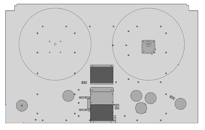
Here’s the model:
Film travels from left to right, and can be A or B wind. It goes around the bottom left roller first, over the top left roller, across the gate, down through the three rollers (the bottom is the capstan), around the bottom right, and up onto the takeup reel. The thread/unthread sensors are right to the left of the gate and just to the left of the bottom right roller. All the rollers are 70mm PTRs, including the capstan.
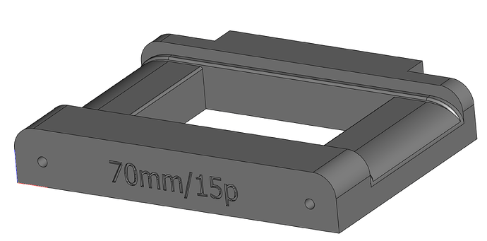
It’s curved slightly on the edges but flat in the middle. This may still require some tweaking, which we can do easily once we get the new CNC router set up. The gate is held onto the deck with the same pins the Cintel scanner used. They’re 1/2" stainless registration pins that stick out about 3" from the deck surface. They enter into the back of this gate, and then screws in the front go into tapped holes on the registration pins. Once tightened, the back edge of the gate is pulled flush to the deck and is perfectly perpendicular to it. We left a little room above the gate so we could potentially put in a pressure plate system in the future if necessary.
The PTRs on either side of the gate should provide enough tension to keep the film taut. This is very similar to how our Lasergraphics scanner does it.

