Sasquatch 70mm scanner

We have made another hardware change, and @matthewepler you might be interested in this. We’ve decided not to build a custom motion control system, which is what we had been working on. Instead, we’re using Teknic’s new ClearCore controller. This works natively with their motors, which is nice, but it’ll also work just as well with other motors and sensors. It’s running on an Atmel chipset. You can program it using their tools or the Arduino IDE. It has a ton of I/O, and can supply power to motors, etc. If you were to use steppers that have built in drivers, you could just plug them in directly to this (or plug external drivers to this, between controller and motor). It’s only $99.

It’s so cheap that we bought two, one for the person coding the firmware on it, and one to install in-house, and this should greatly speed up development over the next few weeks because we can just email the firmware updates now.

Here’s a silly video Teknic made of a robotic bartender using one of these controllers: ClearCore Industrial I/O and Motion Controller Platform; $99

2 Likes

Oooh interesting! I’ll definitely check that out @friolator . Thanks for bringing it to my attention. Have you tried it out with your machine?

The person doing the firmware for us should be done with the first revision soon, so I hope to start testing it in the next couple weeks.

In the mean time, we have the frame grabber/camera under software control, so over the next week I’m building a simple test app for all the post-scan image processing (frame alignment, color channel merging, etc), so that we can test it on a variety of hardware before settling on a computer to run this in.

2 Likes

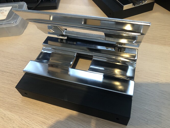
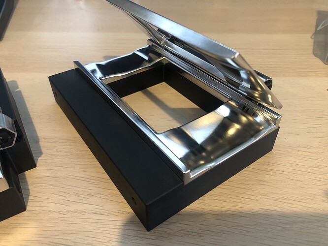
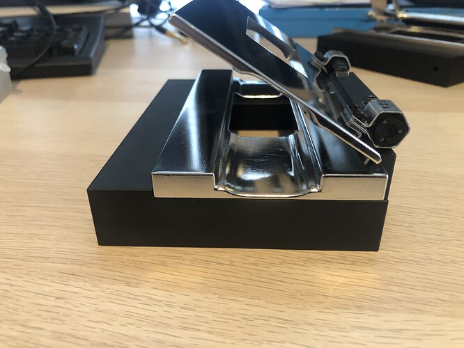
Our new gates arrived this morning. We completely redesigned the gate system to include an integrated pressure plate that’s held on with torque hinges that hold the gate in whatever position you set it to. (unfortunately the ones we ordered require too much torque to open, so we’ll need to swap them for a less intense version). Here are the gates for 15 perf IMAX, 10 perf 35mm (for a special project we’re working on), and 4 perf 35mm. With these we should be able to handle most formats. We’ll probably make one for 28mm as well.

The base is the same for all three gates, so we can easily upgrade the skid plates if needed. They’re anodized 6061 Aluminum and the skid/pressure plates are 316 stainless, electropolished. not a perfect mirror finish, but no burrs or things that will catch dust, so we should be good to go on these. To save money on the manufacturing, we’re using the same pressure plate for the 10 perf and 4 perf gates.

2 Likes

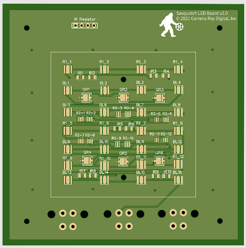
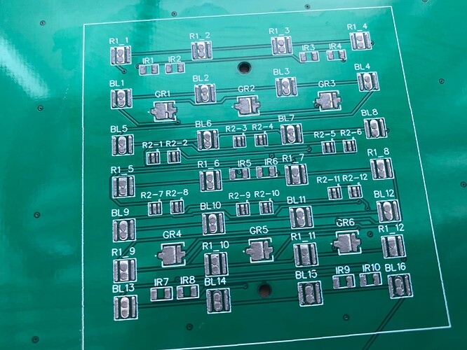
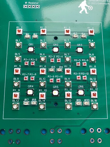
Just sent the lamphouse PCB off to be manufactured. I ended up doing this myself, after our second electrical engineer couldn’t meet any of our deadlines. We had to ditch all the work she did over 3 months and start from scratch.

In the end though, I think this is a better setup as it has separate components for the two red channels, green, blue and IR. All the LEDs are concentrated into a 50mm square, so we can make a little snout to feed into an integrating blob (it can’t quite be a sphere in our current setup, so it’s more a curvy, organic blobby thing. I’ll post pix when I print that part. If it works, great. If not, we’re planning to re-machine the box that would hold it anyway, and could more easily make it a more traditional integrating sphere with a single input port at 90 degrees to the view port at that time.

The temporary driver for the LEDs is a pair of Sparkfun 3-channel Picobuck LED buck converters, the current output of which happened to match our LED forward current requirements for all but the IR channel. These converters take a PWM input from the microcontroller, but output constant current. they’re a few dollars each and can be mounted to a DIN rail in the chassis. Once this is all up and running there will be a redesign that includes thermistors on the LED board to monitor temps, and a custom LED driver, based on the Sparkfun design, which is open source. But it’ll be in a form factor that works better for our setup.

The IR channel can be enabled/disabled with that jumper at the top. That’s for a current-limiting resistor, which will change the max brightness of the LEDs. We can fine-tune from there with the PWM signal. Until this is pointing at the camera, we really don’t know how much IR light we’ll need to make a dust map, so this part is a bit experimental.

2 Likes

3D printing the integrating sphere (blob) this afternoon. Basically this drops into what was the lower mirror housing. It’s essentially a long rectangle with a 45 degree cutout at the bottom (for where the mirror once was). Inside this box is mostly curved to try to get the light bouncing around as much as possible. There’s a 60mm port on the long side, connected to the LED board by a tube that will be lined with some mirrored material. The viewport at the top is sized so it’s about the same as the gate. Odds are this will need to be cut a bit bigger though, once we get it in.

We’re printing this in two halves, sliced vertically down the middle so that it can be printed without internal supports that would have to be removed. It’ll be sanded smooth, then spray painted (primer), followed by white house paint/barium sulfate. The two halves are joined, glued together, and dropped into the housing.

This whole setup will likely change to a true sphere soon. I think we’ll swap the angled bottom section for more of a box, and that will allow for an actual sphere. But for now, this should do.

1 Like

Looking great so far, I’ve been curious about different shapes instead of a true sphere. Does the scanstation actually use a bit more of a square shape?

I’m working with a sphere around 88mm. I’m tempted to try a large 45mm square 100w cob, but due to space using some tube or mirror to bounce it into the sphere.

Are you going to overdrive your LEDs? Or it’s not needed due to the intermittent motion?

It’s a glass integrating sphere, that gives the best diffusion, and it’s enclosed so there’s a flat piece of glass on top of the light component as well. Then my understanding of the gates is that they’re designed in such a way as to prevent dirt and dust from falling directly on the glass during scanning. If space is an issue you can use opal diffusing glass (or another piece of flat diffusing material) instead.

The enclosure is a rectangular box, but is sealed so I’ve never seen the inside of it. Lasergraphics refers to it as an integrating sphere, and it would be relatively easy to get a sphere shape inside that of sufficient size to cover 35mm film.

I don’t think a square would work. The idea is to try to bounce the light in every direction, and the sphere will do that much more effectively. Ours is a bit of. a hybrid with a couple flat surfaces, but. mostly curves inside. This is because the bottom mirror housing, where the original design had a mirror shining the light up from below, cuts the bottom of the enclosure at with a 45 degree angle. So right now I’m working with the space we have in order to get something in there for testing. I will eventually redesign this lower box anyway, and at that time it’ll be a true integrating sphere.

No. they’re running at their rated specs, to maximize their lifespan and their consistency.

Dirt can, and does, easily fall onto the glass plate at the top of the sphere, and this can have an effect on the scan. We check and clean the glass under the gate multiple times per day. The gate itself is just a block of aluminum with the skid plate on top, and an aperture for the gate opening. It’s open air, so if something falls through the aperture, it lands on the glass atop the lamp house. The inside of the gate is a pyramid shape with the top cut off a bit bigger than the gate aperture, and the walls lined with some kind of mirror material, to bounce the light around a bit more.

Some more updates:

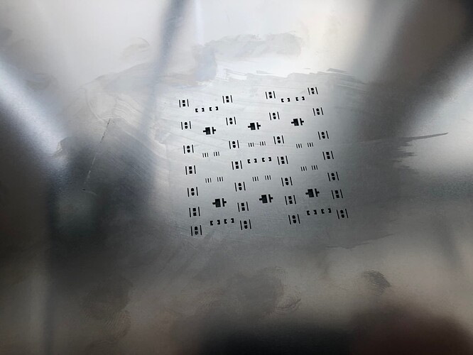
The LED boards came in, and after trying (unsuccessfully) to solder one up without the solder stencil that was delayed in customs for a week, we finally have a working board. So much easier with a solder stencil and a reflow oven than trying to do this fussy stuff by hand.

Took about 30 minutes to assemble that board, and the vast majority of the time was manual pick-and-place on the components.

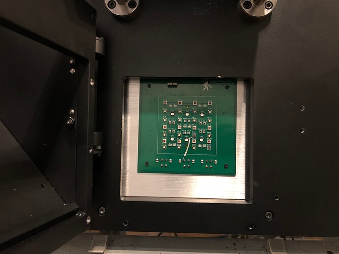
This board is smaller than the previous one, which mounted directly to the back of the scanner’s deck plate. So I designed and cut on our CNC router an adapter plate to mount this to. It acts as both a mounting plate and a heatsink. Now the board is mounted pretty close to the back of the integrating sphere, so the next hardware bit is to make a 3D printed adapter that shares the M2 mounting screw points for the board, and allows for a snap-in cone to connect to the back of the sphere (AKA: blob).

This is of course a prototype, and we expected to have to make some changes. For one, I completely miscalculated the voltage requirements for all the blue LEDs, so I had to cut 6 of them out of the circuit, thus the jumper wire you see here as we bypass the last few.

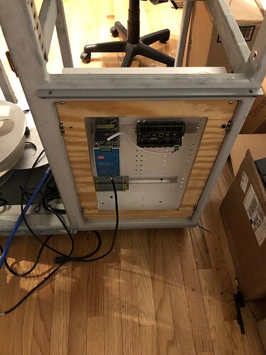
And then today, I cut a temporary wood mounting plate for the control box, where the power supplies, ClearCore controller and LED drivers will live. This is wood because we want to see how it works in this location. May end up moving it to the front of the unit, where it will be behind a hinged door, but it kind of depends on how the rack mounted stuff (like the computer and some drawers to hold gates and such) all fit in the front.

There are quite a few design changes in store for the LED board, which we’ll finalize hopefully next week once this is all wired up and we can take some test images. Namely:

  • Aiming to use fewer LEDs, but this will require testing to see what the actual light output and exposure speeds we’re looking at are.
  • All of the LED traces will be routed by hand on the next one, with the goal of making a more compact layout that also has wider traces to help with heat dissipation. The idea would be to group the like colored LEDs in rows of just that color, and to try to get all the traces onto one side of the board so we can make a thick Aluminum PCB to help wick away heat.
  • Might add a thermistor to the board to monitor temps.

The idea on the LED grouping is that it shouldn’t matter if all the blues are clustered together, rather than spreading them out like we have here, since they’re feeding into the integrating sphere. If we can make it more compact, we can make a simpler 3D printed tube that guides the light into the sphere. that’s the plan, at least. First, though, testing…

3 Likes

Looking great, nice work with the soldering.

Do you have an algorithm for auto RGB mixing similar to the cine2digits? Or will it be a manual process setting levels in the beginning?

thanks. the reflow oven makes it super easy and neat!

Our scanner doesn’t mix RGB to make white. It takes three images of each frame, one with red, one with green and one with blue, with a monochrome camera. Then in software those channels are combined. If you take a color image into Photoshop, and separate the channels, you’ll see they’re represented as greyscale. Same basic idea here.

So we have to do some real-world testing to make sure we’ve got the right intensity on each channel’s light.

That said, if you were mixing separate RGB LEDs to make white, the easiest way to figure that out would be to do a series of tests where you look at the scan of some color charts, on a waveform and vectorscope, adjusting the relative balance as needed. That should get you pretty much dead on.

1 Like

Half of that is just marketing too. All the companies do it basically the same way. You have to diffuse LED or you won’t have an even light source for your scan in the first place! but with the diffusion you also need to get the film at the optimal distance from the light to get the scratch removal.

Are the LEDs selected to get the maximum possible colour separation (that is to minimise contamination from the unwanted dye channels)?

Yes. Different reds for neg and print, too.

1 Like

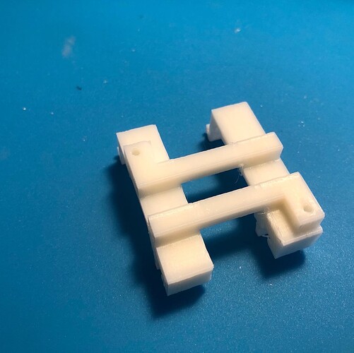
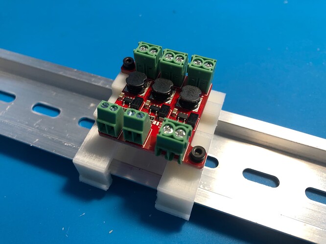
Can’t buy it? make it. This is the 3D printed mount, designed and printed in a day, for our temporary LED driver (a simple 3-channel buck converter that outputs constant current to the LED board).

In case you need a DIN rail mount for a SparkFun Picobuck, here’s the file

Some progress this week on wiring up the beast.

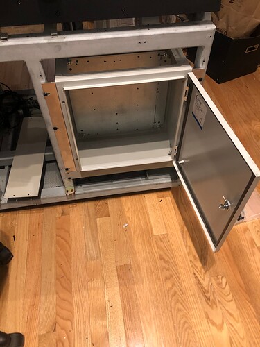
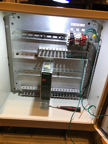
A robotics company that used to be in our building moved out, leaving a bunch of electrical boxes behind. So I grabbed some and fabricated some rack mount ears for one. The Cintel chassis we’re using as a base for this scanner has two 19" rackmount bays behind doors at the base of the chassis.

So the right side is where I installed the box:

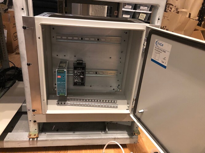
Installing some DIN rails:

And some cable management and terminal blocks for the AC input.

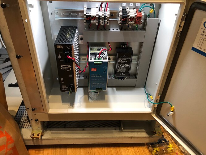
All of the power supplies installed and wired up. Neat and tidy with those cable troughs. The big PSU on the left is for the ClearPath servos. The 24V PSU in the middle is for the ClearCore controller. The small 36V PSU on the right is for the LED drivers. Still need to connect the feed/takeup/capstan power connectors to the terminal block at the top, and feed this box some 110V AC, but otherwise, power is done.

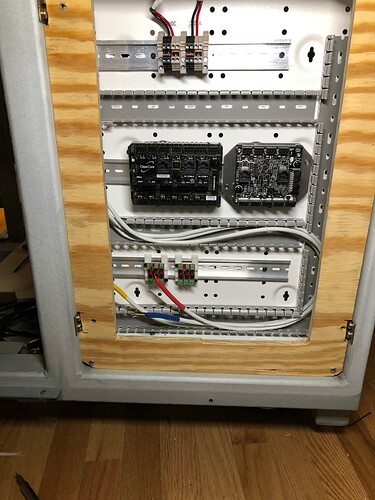
Also started wiring up the control box on the back. 24VDC and 36VDC power comes into the block on top from the power box at the front of the unit. ClearCore and its I/O expansion unit are in the middle, and LED drivers below. There’s some room in here to install a few relays as well, for turning on and off cooling fans on the camera box and chassis, as needed. This thing with the plywood is temporary. The back of the Cintel had a bunch of BNC connectors for hooking up to video gear, and we pulled those out. Odds are we’ll fabricate a simple panel to hold this box, and then another that uses the existing hinges for a door over it.

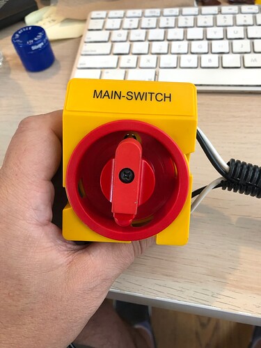
Still trying to decide if I want to repurpose this utterly ridiculous power switch. If we use it, it’ll be prominently displayed on the front of the machine. Because it’s ridiculous.

2 Likes

I’ve been looking more into those ClearCore controllers, in the past were you hoping to use an arduino?

I’m looking more into using an arduino for my project of an 8mm continuous scanner, but I’m reading that connecting rotary encoders seem to need some workarounds.

I’m assuming the ClearCore is much easier to setup with common servo motors and rotary encoders?

At one point an Arduino was in the mix. We were also looking at building our own microcontroller based on an ARM chip. The ClearCore was a bit of a no-brainer for us, in part because three of our motors are made by Teknic and are essentially plug and play with this controller. The four large connectors in the middle are specifically for their ClearPath motors. We’re using one for feed, one for takeup, and one for the capstan drive. Adding additional I/O is easy - just plug in a CCIO-8 board ($45), and connect it with a short ethernet cable, to get additional ports.

Programming the ClearCore is done in C++. There are two ways to do it - using the Microsemi Studio (formerly Atmel Studio) IDE, or the Arduino IDE. There’s a layer you can use that lets you program the ClearCore like an Arduino. However, I don’t know if that’s more limited. We hired an embedded systems engineer to code the firmware for us and he’s using the Teknic API. Looking at what needs to be done, and the sample code provided by Teknic on their site, I’m pretty confident I could have done it myself, but …you know, time.

For non-Teknic motors, you’d use some of the smaller connectors around the outside of the box, and those work a lot like the Arduino. I never got into dealing with encoders with the Arduino, but my understanding is that you need to work with that at the interrupt level, and part of the issue with Arduinos is that they use cheap, relatively slow, chips, which can make things challenging if you need to react quickly. Again, I haven’t done this, but was dissuaded from using it by people who know, who said it’d be a huge hassle to get interrupts to work with encoders on the Arduino.

While the ClearPath motors are a bit expensive, one nice feature is that they have integrated drivers. The MPVC motors (note the P in the model name), have positioning capabilities, because they’re closed loop motors. This lets you accurately count your position. We’re using one of these for the capstan drive, and MCVC motors for feed and takeup, just to keep the tension on the film.

We’re also using Schneider Mdrive steppers for the camera and lens positioning motors, and those are also self-driving, closed loop motors. It may be worth looking into using something like that, where you can tell the motor “go X steps” or “go to X position” and just be confident it’s doing it.
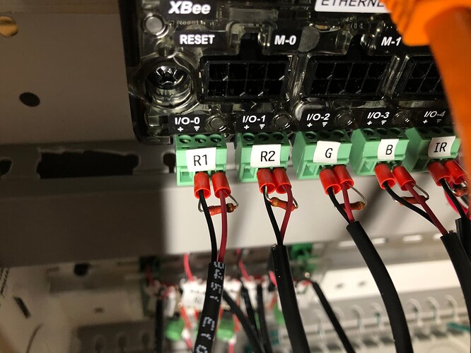
Been a busy couple of weeks. We have the ClearCore set up and lighting up the LEDs correctly, but in the process of initial testing managed to fry half the green LEDs (don’t ask). New diodes on order, and a new board will be assembled next week. Meanwhile, hacky voltage dividers on the ClearCore so we don’t overdrive the LED driver signal:

The Sparkfun Femtobuck drivers we’re using are a little messy since they’re small and hard to mount. So we decided that since the schematic for that is open source, we’re going to make a new driver board that just uses 5 of those, but sharing a physical board. They seem to be working fine so no need to reinvent the wheel. The voltage dividers will be on that board and not in the form of a little resistor jumping the connectors like this.

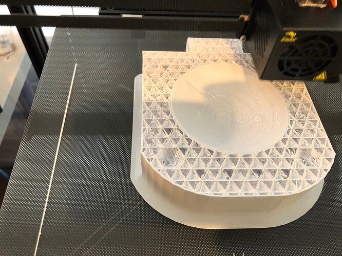
The Integrating blob I mentioned above doesn’t work well. it’s just not flat light because part of it gets cut off in the field of view of the camera. So we are completly removing the bottom housing for this and 3D printing a whole integrating sphere/housing as one unit. It’s a massive print - about 8" x 6" x 6" with a sphere in the middle and entry and exit ports. At low quality, it’s a 13 hour job on a pretty fast Creality Ender 6 printer. If this works well, we’ll print one up with better quality. Anyway, while the new integrating sphere prints:

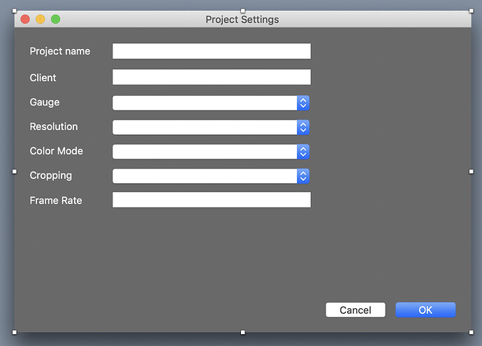
…I’m starting work on the user-facing GUI for the scanner. Right now we have all the individual components written as separate small applications, and one nice thing about Xojo is that you can open up a couple projects and drag/drop components from one to the other. Code comes with it, and that makes it easy to build up a complex app like this. We currently have separate applications for taking pictures, controlling motors, turning on and off the LEDs, testing the TCP comms between clearcore and PC, and the beginnings of an app that will be used to generate the configuration files used for each gauge of film (which tells the scanner where the camera/lenses have to be positioned, define the registration reference points (perfs, usually), and some other utility stuff.

4 Likes