@Manuel_Angel
For the motor control it has already been mentioned that the excellent pigpio library is no longer available on the PI5. But reading more in detail the pigpio documentation I see that it is possible to remote network control the pigpiod daemon. So it would be easily possible to continue using for the motor a RP3 or RPI4 running pigpiod. Maybe easier than using a pico or an arduino and no change in your software ?
Hi @dgalland,
I hadn’t thought of this possibility.
@PM490 suggested the option of using a Pico microcontroller, which I personally didn’t know about either.
Although it takes a bit of time to get to grips with how a new microcontroller works, in this particular case, using MicroPython, you can get very good results in a short time.
The designers of the Pico microcontroller had the brilliant idea of including programmable peripherals called state machines in the microcontroller itself. These state machines, once programmed, operate with their own clock, independently of the CPU, so that the timing of the motor control pulses is very precise.
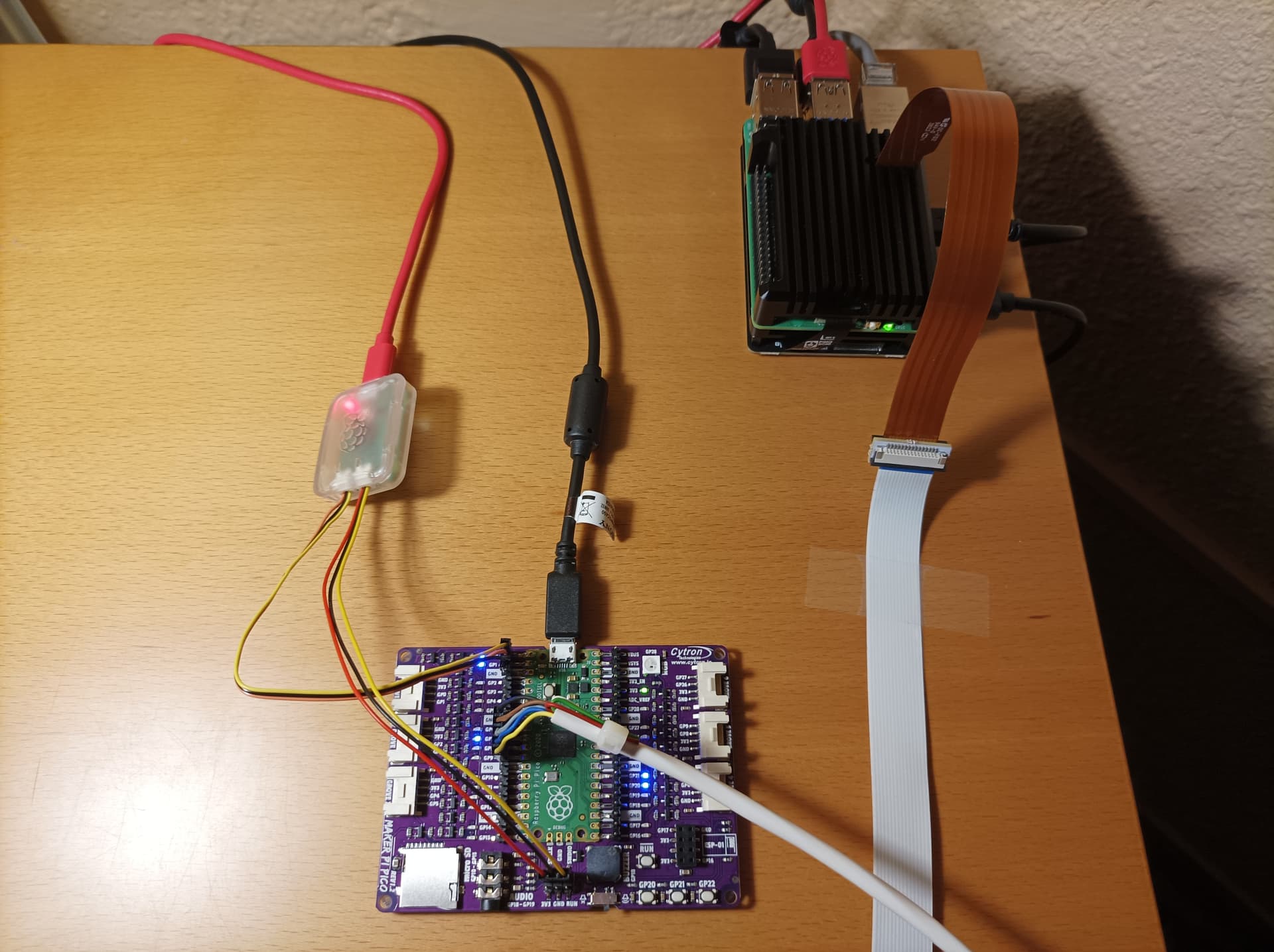
RPi5-Pico communication is done relatively easily using a USB port on the RPi5 that is bridged to a UART on the Pico, using a Raspberry Pi Debug Probe and the Python serial module.
Using the Pico microcontroller also has the advantage of immunizing the system against future changes in the RPi hardware.
Here is a picture of my RPi5, with a prototyping board incorporating a Pico microcontroller and the Raspberry Pi Debug Probe.
3 Likes
Thanks @Manuel_Angel I’ve used it now for several months and really like the performance (FPS) improvement of this design. For others that have missed my earlier post on it you will find it here https://forums.kinograph.cc/t/9-5-mm-scanner/2629 (June 3rd)
2 Likes
Hi @Moevi.nl,
Thank you for your encouraging words.
I am glad that you are finding this version of the software useful.
Although I finished developing this version several months ago, I have not yet released it for general use, I have only sent it privately, as in your case, to users who have requested it.
The reason is that I find the software installation on the Pico microcontroller somewhat complicated and I want to make a detailed manual.
To make the software installation on the RPi5 easier, I am trying to make a .deb package or package it in an .AppImage file.
Kind regards
1 Like
I tried and it works without problem. As simple as this:
pi = pigpio.pi(‘192.168.1.152’)
So it is possible to recycle an old PI3 or PI4 to control the motor via the network from a PI5 with the Pigpio library with all its interesting possibilities.
3 Likes
Hi @dgalland,
This is indeed an ingenious solution, instead of connecting to the pigpiod daemon running on the localhost, we connect to a daemon running on another RPi.
We also take advantage of an old RPi that we have forgotten in a drawer.
Thanks for sharing.
1 Like
In the name of simplifying the setup… just wondering if the debug probe could be eliminated from this setup considering it’s basically another pico?
Hi @drew,
Indeed, the RPi Debug Probe is based on a Pico controller.
The problem is the software. The RPi Debug Probe runs software that, among other things, facilitates communication between our RPi 5 and the Pico microcontroller.
With this software, the Debug Probe acts as a bridge between a USB port on the RPi 5 and the Pico UARTs. RPi 5-Pico communication is greatly facilitated.
It is also very useful when loading software onto the Pico or even rebooting the Pico using OpenOCD software in both cases.
Hi @Manuel_Angel
Once the software is developed, it is possible to upload the compiled/link .uf2 file using the “special USB Mass Storage Device mode”.
From the PICO datasheet
The simplest way to reprogram the Pico’s Flash is to use the USB mode. To do this, depower the board, then hold the BOOTSEL button down during board power-up (e.g. hold BOOTSEL down while connecting the USB). The Pico will then appear as a USB Mass Storage Device. Dragging a special ‘.uf2’ file onto the disk will write this file to the Flash and restart the Pico.
The USB boot code is stored in ROM on RP2040, so can not be accidentally overwritten.
I actually do not own a probe, although I probably should for the development portion.
Hi @PM490,
Certainly, using the BOOTSEL button is the easiest way to load an executable file into the Pico’s memory.
I find it particularly inconvenient because I have to disconnect the Pico’s USB power supply.
Using the openocd utility, ELF executable files can be loaded into Pico directly from the command line, using Pico’s SWD interface and Debug Probe.
In the specific case of MicroPython scripts, it’s not possible to use the BOOTSEL method or the openocd utility; they are not directly executable files. They must be saved in the Pico’s memory and then executed with the MicroPython interpreter.
To save scripts to the Pico, it’s very convenient to use an IDE, such as Thonny or VSC.
Anyway, thank you very much for your post. It’s always helpful to discuss these issues and keep the forum lively.
Regards
You are right, I use C… sorry, did not think of micropython.
I didn’t see your PICO python code… is it only the stepper and the light?
If it is not too complex, I can write you a version in C, so you can share the .UF2 file for those using your Dsuper8.
1 Like
If uf2 is the goal, it looks like ‘GitHub - raspberrypi/picotool’ could be used to dump the flash of a programmed pico to uf2 and wouldn’t need the rewrite to C.
1 Like
Thank you very much for your kind offer, but I really don’t think it’s worth the effort of creating a C version.
The MicroPython script has about 300 lines of code.
Its main purpose is to control the stepper motor and the lighting, although it also performs other secondary functions:
- It identifies itself to the RPi5.
- It captures and executes requests from the RPi5.
- It sends information to the RPi5.
For these functions, two Pico state machines are created and programmed in the MicroPython code.
One of the machines is used to send control pulses to the motor, a function performed with great precision. Each state machine has its own clock and operates completely independently of the CPU.
The second machine is used to display a special blinking on the green LED associated with GP25. This is not just a decoration. With each blink, the machine stops, and with each iteration of the main software loop, the machine restarts, providing a permanent visual indication that the software is functioning correctly. If the green LED doesn’t blink, it means without a doubt that the software has crashed.
1 Like
Thanks for the heads up.
I wasn’t familiar with this software. I’ll look into it; it might make installing the software on the Pico easier.
1 Like
Hi Manuel,
I’ve gone down the route of using an RPi 5. I basically skipped over the Pi 4 due to the difficulty in getting them. I did a somewhat sizeable project using the Pi3 model B. For that project, I did not want WiFi or Bluetooth capability. I’ve picked up a Pi5 8Gb, got the NvME adapter, it’s certainly equipped for the task. I am now mostly focused on the hardware side for the moment. Certainly, though, I am interested in a Pi5 solution.
Cheers, John
Hi @John_Bower,
The main problem with the RPi 5 is the lack of a good Python library for managing the GPIO interface. The excellent pigpio library is incompatible with the RPi 5, at least for now.
Following @PM490’s suggestion, the RPi 5 version of my software uses an RPi Pico microcontroller. It works flawlessly. RPi 5-Pico communication is seamless, using an RPi Debug Probe.
In my device, for controlled film transport, I use an old modified projector.
All projectors work in a very similar way: they have a main shaft that, with each revolution, causes the film to advance/rewind exactly one frame.
Therefore, transport control is extremely simple. Simply send the stepper motor the number of pulses required to advance one frame.
This way, in my software, at any time, it is possible to position the film on any frame, both forward and backward. The image file name reflects exactly which frame it belongs to.
The only problem may be the difficulty in digitizing films with severely damaged drive holes.
I assume you also plan to use the RPi HQ camera, which can be controlled very well with the picamera2 library.
If you’re interested, I can send you the download link for the RPi 5 version of my DSuper8 software.
Best regards,
Manuel Ángel
Sure, I would like to take a look at your DSuper8.
If you are just counting steps, then I imagine you aren’t looking at a photodetector like on the T-Scann. I am leaning towards a friction drive like T-Scann. Many years ago, I had a Moviestuff, Workprinter, which was a modified movie projector, I had some successes, but it also chewed up some sections of film, that motivated me to build me own setup, but that has been on the back burner for many years. The computer, controller and image technology has vastly improved over the 10+ years and I’m jumping back in.
In fact, my device doesn’t use any type of sensor for film advance and camera shutter. Everything is done via software.
Projectors certainly have a bad reputation for damaging films. A friction mechanism is safer for the integrity of the films. However, in my case, after many thousands of meters of film digitized, I can say that my mechanism hasn’t damaged any film.
I’ll send you the link to download the software in a separate message.
Kind regards,
Manuel Ángel
Thank you Manuel. I assume this is running on the Pi5? I’ll go through your previous posts to better understand the implementation.