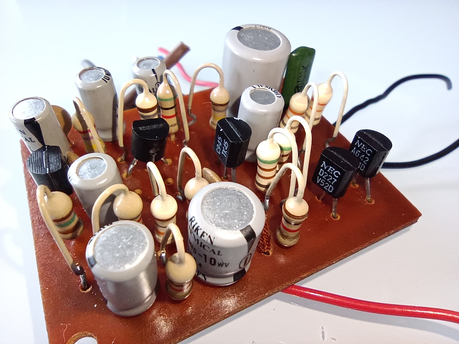
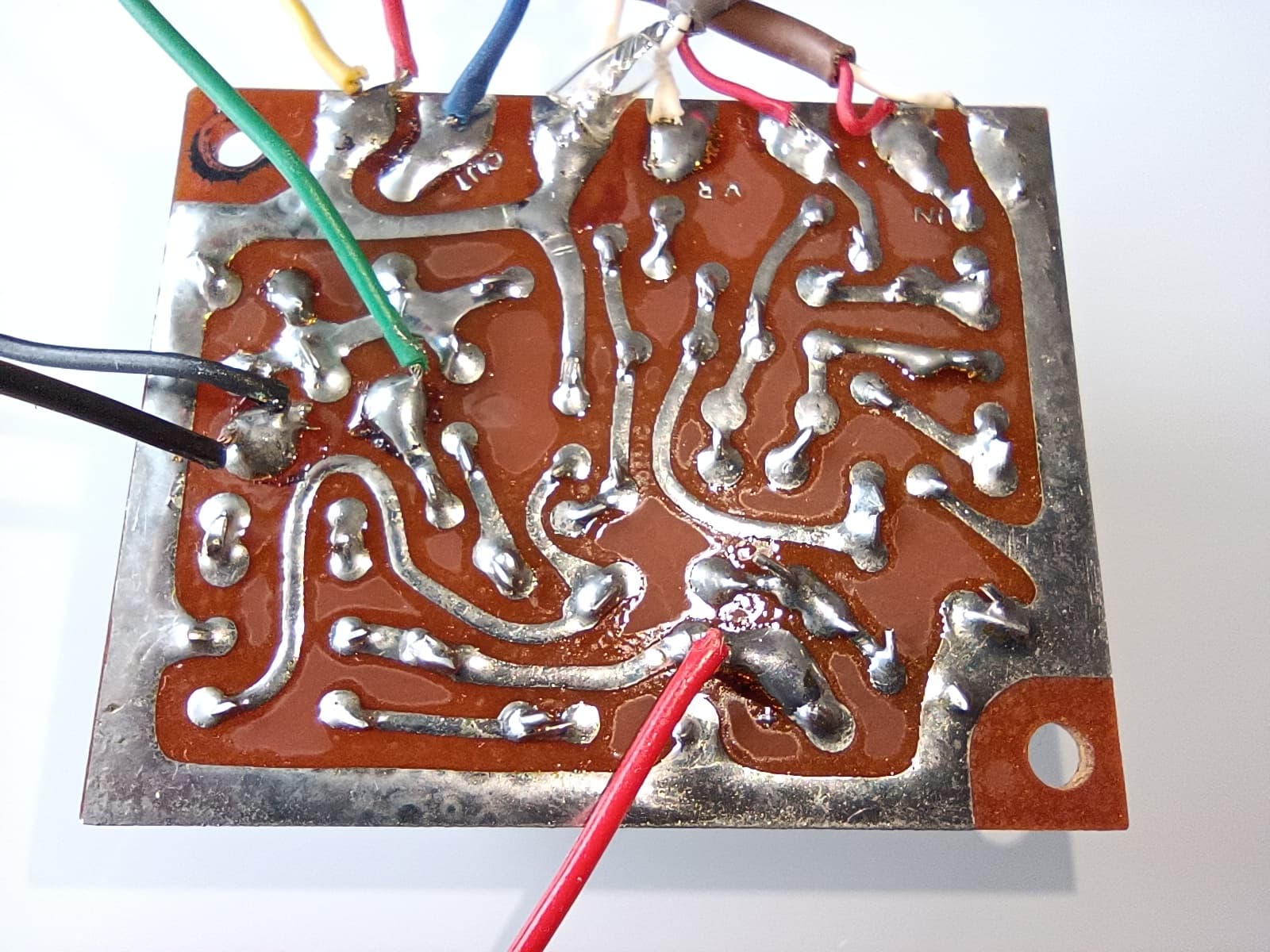
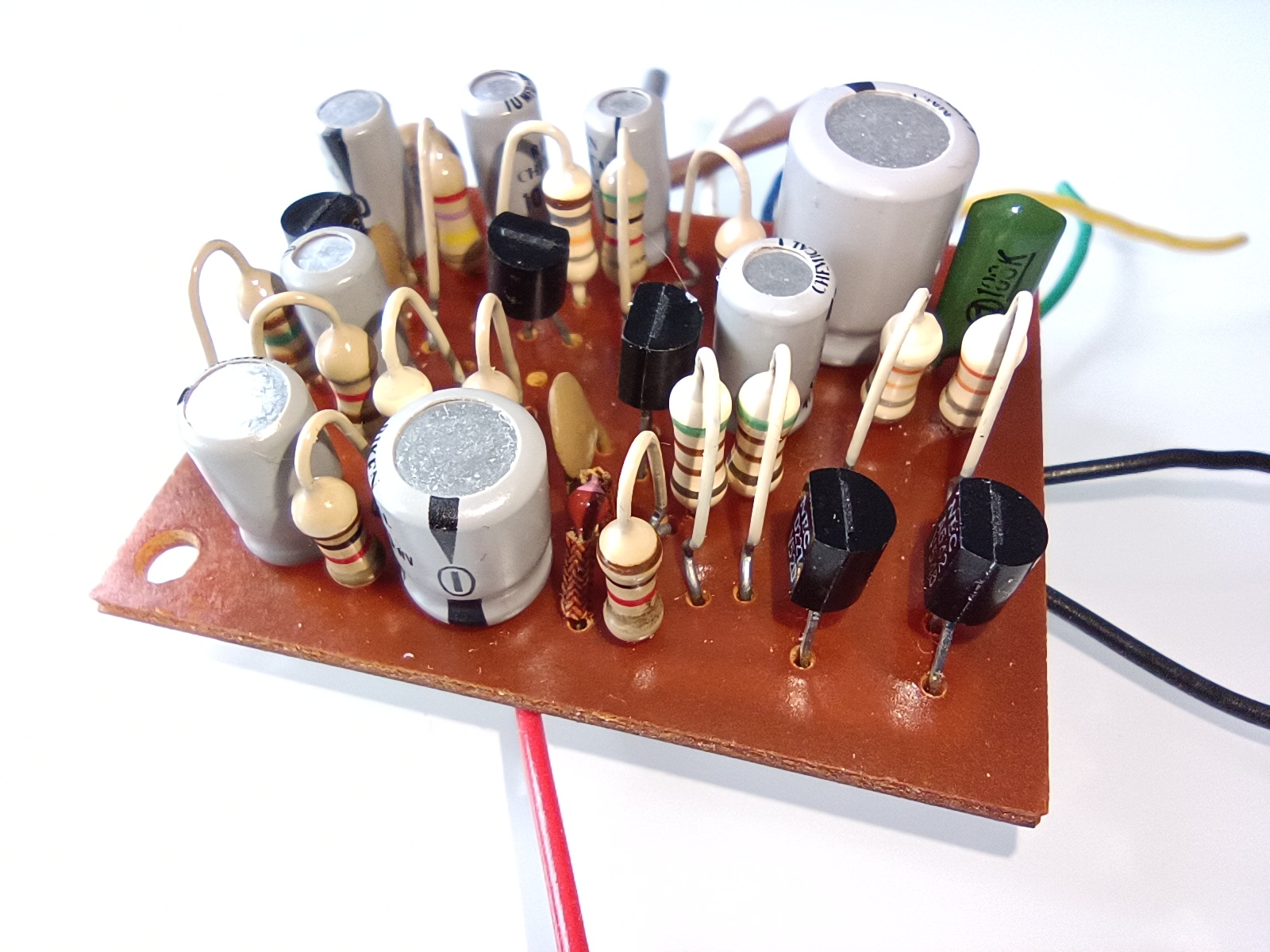
I wanted to know how the amp for the magentic sound head has to be designed. So i reverse engineered the Elmo Sound Monitor 912. Attached are the resulting schematics.
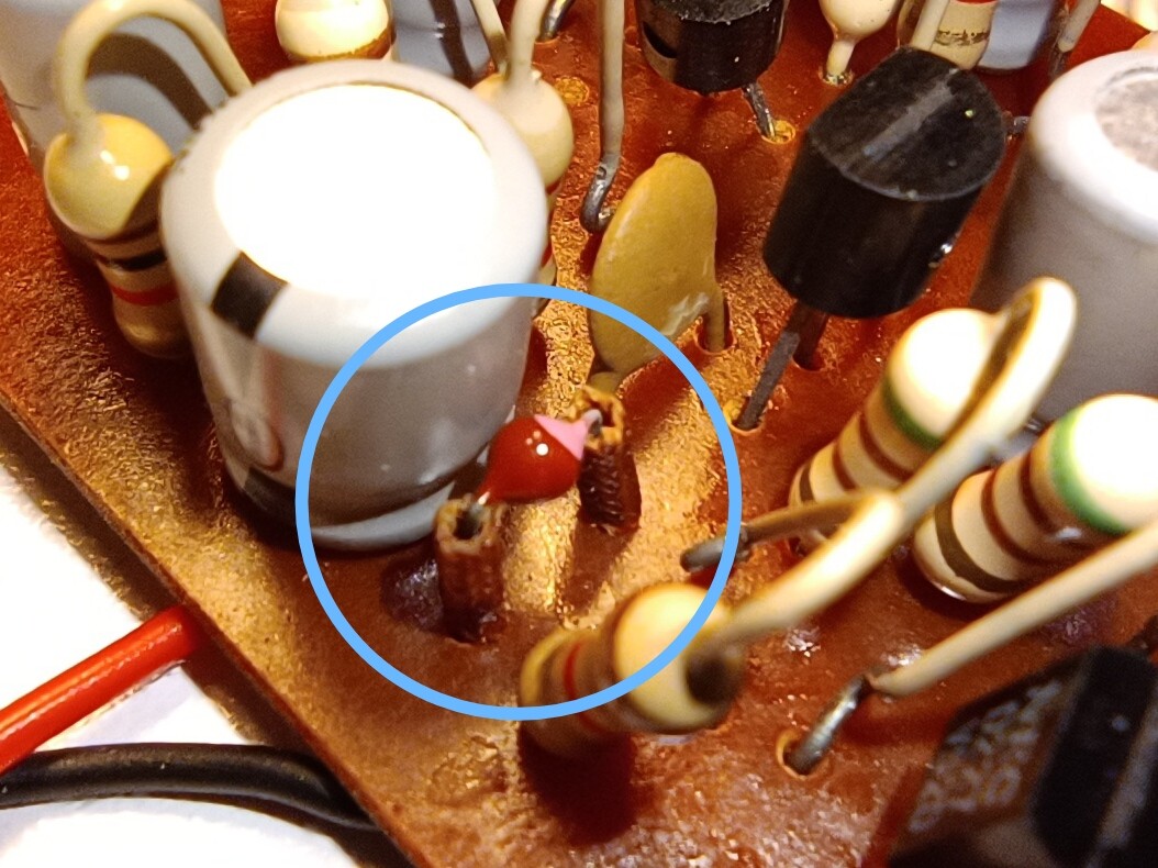
The board runs from 9V and has a headphone jack. There is one part I couldn’t identify. Perhaps someone knows what this is? A diode?
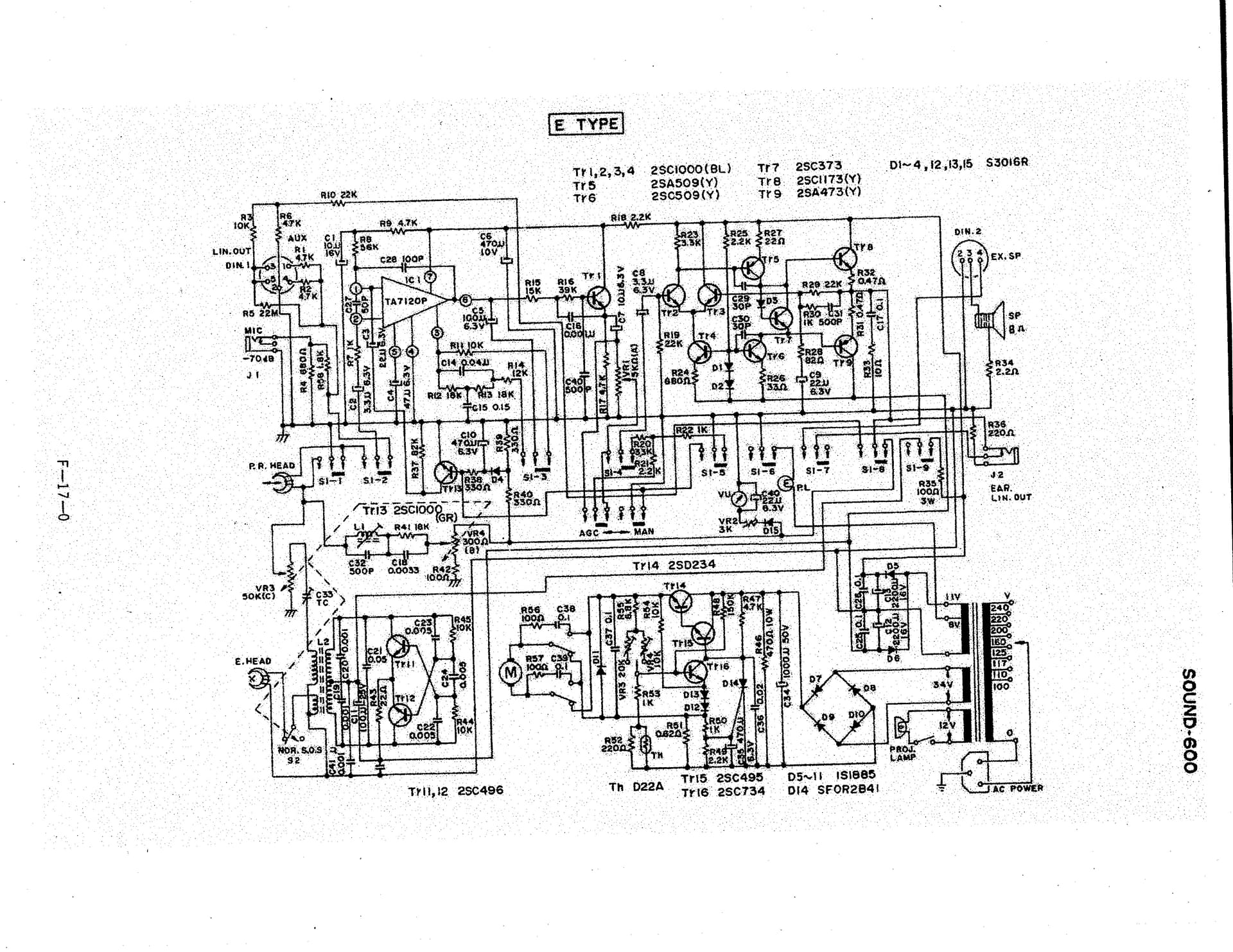
Thank you for sharing this. At some point in time I would like to tackle sound. I got a Sankyo model Sound-500 projector that is not working, and was looking for info and found the service manual for the Sound-600 model and it has the schematic. Here it is in case is useful.
Hard to say, it may be a coil. If you can get your hands on a multimeter, it should be easy to confirm is not a diode.
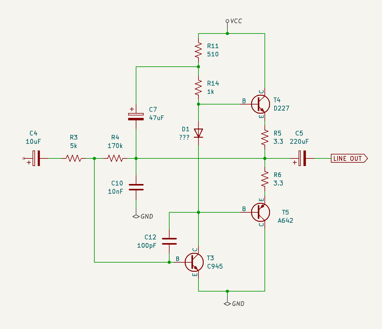
But from the circuit, it looks like you have audio at the output of C4, the circuit to the left of C4 looks like an amplifier with some filtering that includes the unknown part.
I am not familiar with the TA7668, but looks like it would do the trick. The board you show has also an amplifier, there are other board that are only the TA7668.
This post shows the use of a modified tape deck with a sound film head.
That component is so small compared to the resistors! That’s practically surface-mount sized.
I’ve had success in the past asking some identification questions like this at the Electronics StackExchange site. Both times someone gave a great answer in just a couple hours. My curiosity is piqued now, so I’d also be happy to ask over there (with permission to use your photo).
The left side of the schematic is a pretty standard two-stage BJT amplifier, but the right side is kind of puzzling. If the base of T4 really is VCC then it would just live in saturation mode, wouldn’t it? And depending on the nature of the mystery component, T5 might be in the common-base configuration? (Although I’m a little hazy with the PNP configurations.)
The two-tone paint on the device suggests it’s polarized. Maybe it’s something like a small, axial tantalum cap?
I have a multimeter with diode function and have just checked the part. It reads 1.112 V in the T4>T5 direction and 0 V in the other direction, so I think it’s a diode. Would also match the marking on the part. Also, @npiegdon pointed out to me that T4/T5 are connected in a strange way. He was right. B-C were switched.
You were absolutely right. The base and collector were swapped. I have uploaded the new schematics. PM490 pointed out to check with a multimeter. I think it’s a diode (see my last post). I just don’t know the specs for it.
Feel free to use my photos if you start researching.
T4 and T5 configuration is typical, but something is odd with T3, everything on the base is ac coupled, so not sure how that transistor would get some dc bias to work.
Do you intent to build the amplifier discreetly?
I think your idea of the TA7668 should work.
CORRECTION: R4 is the component that provides the bias for T3. R4 is not DC coupled as mentioned above.
I just asked the question over at the Electronics StackExchange and some early answers are already rolling in just a couple hours later.
One of the more interesting parts of StackExchange is the “related questions” search that keeps updating while you type your question. By the time I finished typing, it had dredged up at least two other quite similar questions as the top two matches. (This is to help you avoid asking a duplicate question but in this case it was helpful!)
Both show diodes that are quite similar looking to this one and the first of those two links mentions a high (1.3V) forward voltage like this one.
Within minutes of posting the question someone left this comment:
Assuming the schematic is correct (and it doesn’t look wrong, first glance), D1 sets a voltage bias between the bases of T4 and T5 necessary for class-AB/class-B operation. T3 is a VAS with C12 setting a dominant pole. R4 is NFB and C7 is probably a bootstrap.
I looked up “VAS” and found “voltage amplifier stage”. NFB is “negative feedback”. And bootstrap kind of defies a one-sentence definition.
There have already been two people asking whether the diode’s forward voltage was measured in- or out-of-circuit. I am guessing it was in-circuit since it didn’t look like anything had been reworked in your photos?
Really appreciate your help. Amazing. Also the analysis in the other forum. I measured the diode in place with a Fluke 117. If it helps I would desolder it.
That answer there by periblepsis is amazing. Sometimes it’s hard to believe it’s a completely free service where experts will just swoop in over night and analyze something for you.
I just updated the top post with your latest, complete schematic and mentioned that you’d measured the forward voltage in-circuit.
(Off topic: I’m still fairly early in my own electronics journey–my formal training is in computer science–and I’ve been working my way through the exercises in a few circuits/electronics textbooks toward the goal of actually understanding the stuff in the The Art of Electronics book. So periblepsis’ suggestion that this would be a good circuit to study is perfect for me. I love clever designs that get a lot done with only a few parts. I’ve added this to my list of things to dig into in detail when the time comes.)
Thank you @npiegdon, the responses from the forum are great, I just signed up.
Thank you @mjh1709muc for updating the schematic.
I studied electronics, but it has been longer than I can remember . This article explains well the progression that I was expecting, and why I doubted the base biasing of T3, which the ELMO amplifier design does not use.
The diode has a larger Vf than a typical diode, to have forward voltage close to the total of T4 VBE + T5 VBE.
The reason for the question at the forum regarding measuring the diode is because if done in circuit, would measure the smallest of the diode or transistors be(s). (T4 Vbe + T5 Vbe vs Diode Vf).
What I was missing prior is that R4 is actually providing the bias for T3, since it is coupled without any capacitors to the DC level of the push-pull.
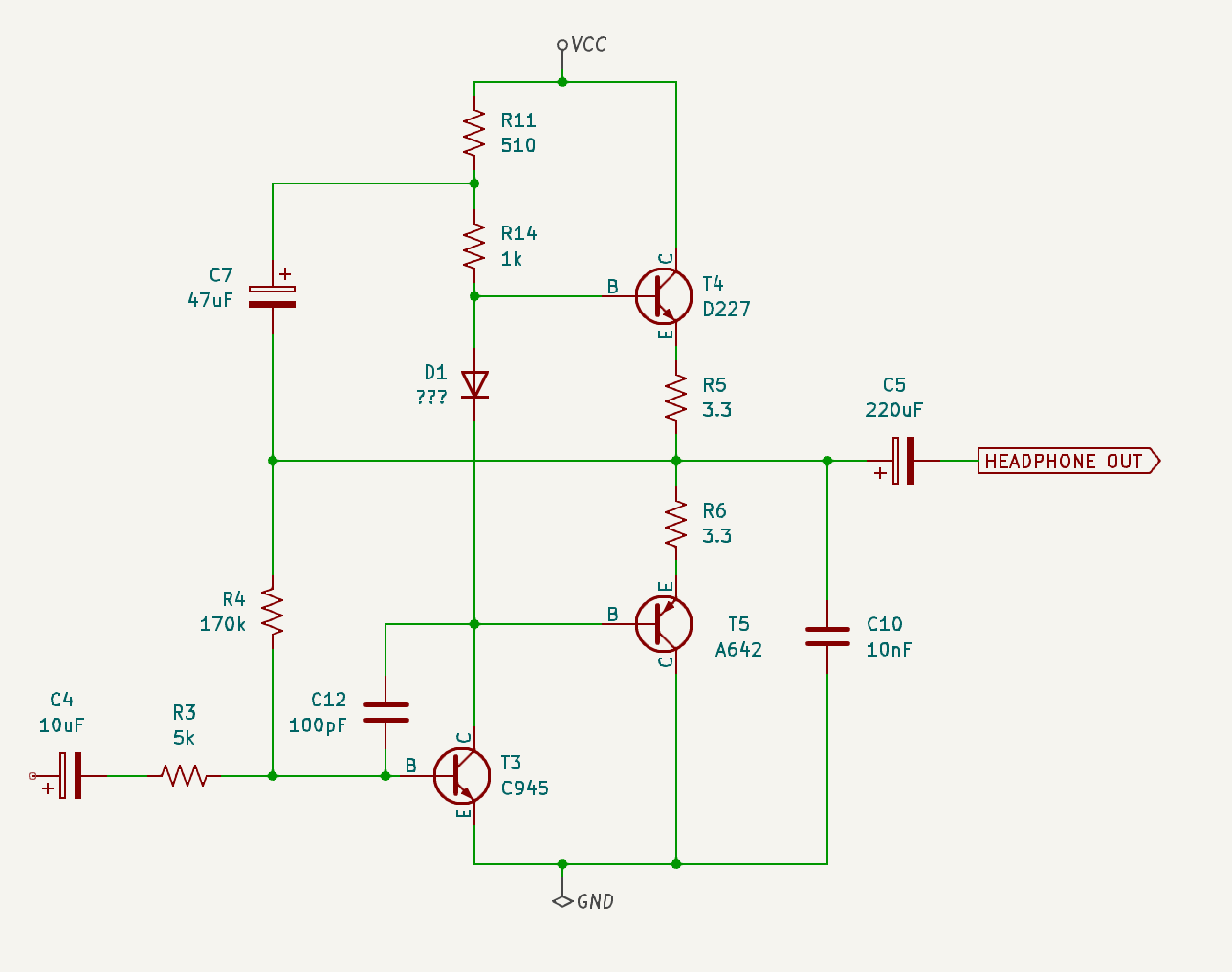
This redraw makes the circuit a bit easier to understand.
… that seems to me to be a quite normal amplifier. Except “D1” used to be normally two diodes in series, in order to create the required bias for T4 and T5.
In the circuit-diagram @PM490 posted above for the Sankyo you can find D5 in series with the transistor T7 which performs the same duty: keeping the bases of the push-pull transistor pair about 1.4 V apart.
@mjh1709muc’s amplifier is a standard circuit. Most importantly, it has a basically flat frequency response. This is different from @PM490’s circuit diagram.
Analog storage media tended to employ equalisation circuitry to enhance performance. I am pretty certain about that in the case of phono input, but I am less certain in the case of magnetic tape heads. There seems to be SMPTE docs about this, but they are behind a paywall. The circuit @PM490 posted above for the Sankyo has a switch-able response curve (flat: R11, filter: R12 to R14, C14/C15, switch S1-3).
Of course, today one could skip this analog equalisation step and do it later digitally in the post. Would however be interesting to find out if there are specific equalisation curves or whether just a flat curve was used in the old times. @mjh1709muc’s amplifier certainly does not do any equalisation.