CineScanner / CineMaster completed

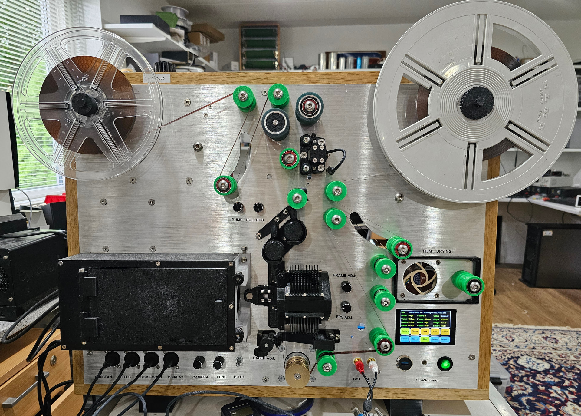
During the last 2.5 years I have created the CineScanner film scanner and the CineMaster control/restoration software (Windows). The system is now completed. This is a rundown of what the system does.

What it is

CineMaster is the Windows program that drives the CineScanner. Together they scan small-gauge motion picture film in real-time, frame by frame, read the soundtrack in sync with the picture, and turn the result into a modern video file. You can scan straight to a finished master, or capture once and do the clean-up, color and encoding afterwards without running the film through the machine again.

Film formats

- Regular 8 mm

- Super 8 mm

- Pathé 9.5 mm

- 16 mm

- Super 16 mm

The scanner (hardware)

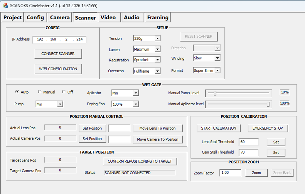
Frame registration: choose laser (sprocket less) registration or classic sprocket-hole registration.

Capture area: Framed, Overscan, or Full-frame — full-frame includes the area beyond the image (sprocket holes and edges) so nothing is cropped off.

Wet gate: an alcohol-based wet gate to suppress the appearance of surface scratches. Alcohol flow, applicator and pump are adjustable, with a drying fan, and Auto / Manual / Off modes.

Gentle film handling: selectable film tension (200 g, 260 g, 330 g, 430 g, 500 g) and winding speeds from Min to Max.

Motion control: frame-accurate transport with Capture, Shuttle (1-250 fps fast preview forward/reverse), Wind, Seek / Go-to-position, and single-frame stepping. Motorized camera and lens positioning, zoom, focus and an optics-calibration routine.

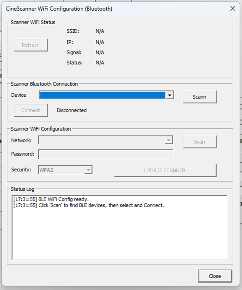
Connectivity: connects over the network (IP address); scanner Wi-Fi can be set up over Bluetooth from within the software.

Camera and image capture

Basler 4K industrial camera. Video output at 1K, 2K, 3K or 4K.

Capture frame rates of 16, 18, 24 or 25 fps with sound, with optional frame-rate conversion between the scanned rate and the target rate. Up to 30 fps scanning without sound.

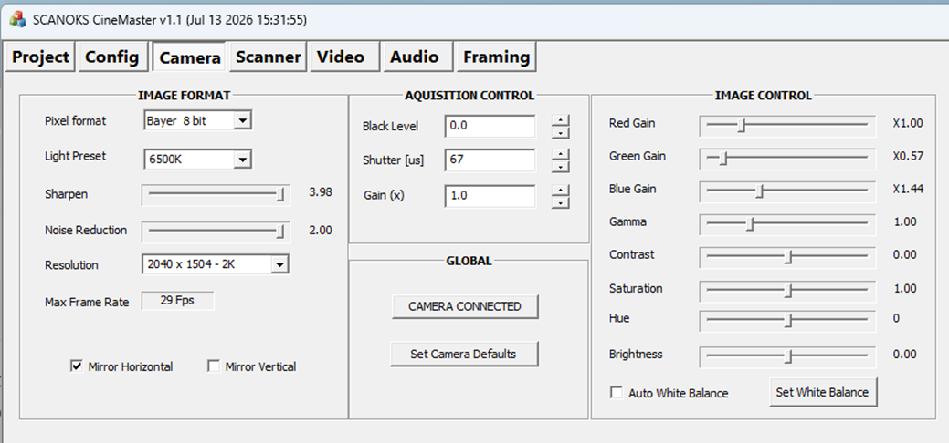
Full camera control: exposure, gain, electronic shutter, black level, white balance (automatic, one-push, or manual red/green/blue gains), color-temperature presets (3000 K, 5000 K, 6000 K, 6500 K), gamma, contrast, saturation, hue, brightness, sharpening and noise reduction, horizontal/vertical flip, choice of dimoraic method, and pixel format / bit depth (8, 10 or 12-bit).

Sound

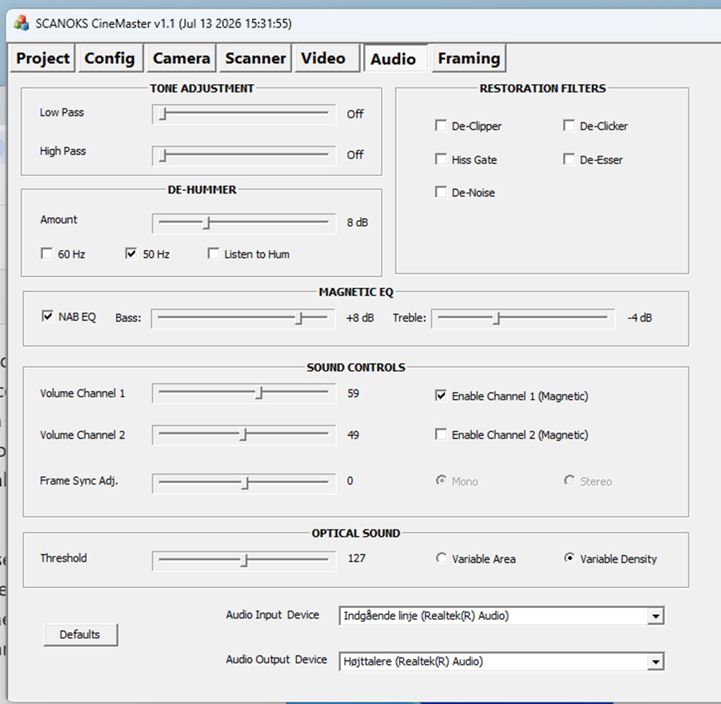
Magnetic tracks (mono and stereo) and optical tracks, read in sync with the picture.

Optical sound can be read by density or by area, whichever suits the print.

Audio restoration and clean-up: de-hiss, noise reduction, de-click, de-ess, de-hum (50 Hz or 60 Hz, with phase invert), distortion removal, SMPTE playback EQ, low-pass / high-pass / notch filters, per-channel level, and picture-to-sound sync adjustment.

Live monitoring and scopes

Live video preview with focus assist and auto-focus.

Parade (RGB waveform) scope, waveform display, histogram, zebra (exposure) warnings and false-color view.

Audio level meters (two channels) and an audio waveform display.

Picture clean-up, restoration and color

These can be applied live during a scan, or as a separate pass on a file you have already captured:

Sprocket based stabilization — vertical, or vertical and horizontal, using sprocket/frame detection.

Image based stabilization — vertical, or vertical and horizontal, using image content.

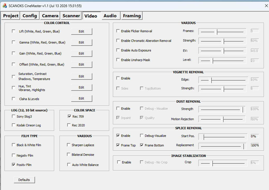
Dust and scratch removal, including fill-in (inpainting) of the affected areas.

DE flicker to even out brightness pulsing between frames.

Noise reduction (two methods) and sharpening (unsharp mask / Laplacian).

Chromatic aberration correction and vignette correction.

Auto exposure with manual EV trim.

Color grading: lift / gamma / gain / offset, white balance, and per-channel adjustment.

Film handling: negative, positive or black-and-white; output in Rec.709 or Rec.2020; log options (S-Log3 or Cineon log) for grading in other tools.

Output — file formats and codecs

Mastering: Apple ProRes, Avid DNxHR and GoPro CineForm.

Lossless / archival: FFV1, HuffYUV, and H265 lossless.

Delivery: H.264 and H.265, including hardware-accelerated encoding on NVIDIA (NVENC) and Intel Quick Sync systems.

8, 10 or 12-bit; 4:2:0, 4:2:2 or 4:4:4 color

Output resolution from 1K to 4K, aspect ratio 4:3, 16:9 or the source ratio, with optional matting.

Audio: PCM, AAC, MP3, AAC, Flac, in various quality settings.

How you work with it

One-pass: scan straight to your chosen final format.

Two-pass: capture once — for example to a lossless or mezzanine file — then re-open it later to grade, restore, adjust sound and re-encode, all without touching the film again.

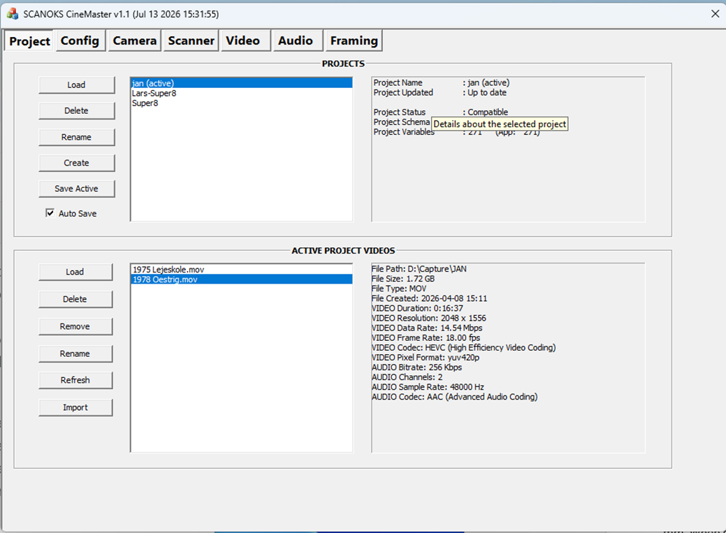
Projects: create, open, save, rename (support multiple files). Full configuration stored with the project
7 Likes

It looks like you’ve done an excellent job. We look forward to you posting details about its construction.

What kind of details are you looking for ?

@Lars_Oksbjerre very cool project, congratulations on your build and thank you for sharing it in the forum.
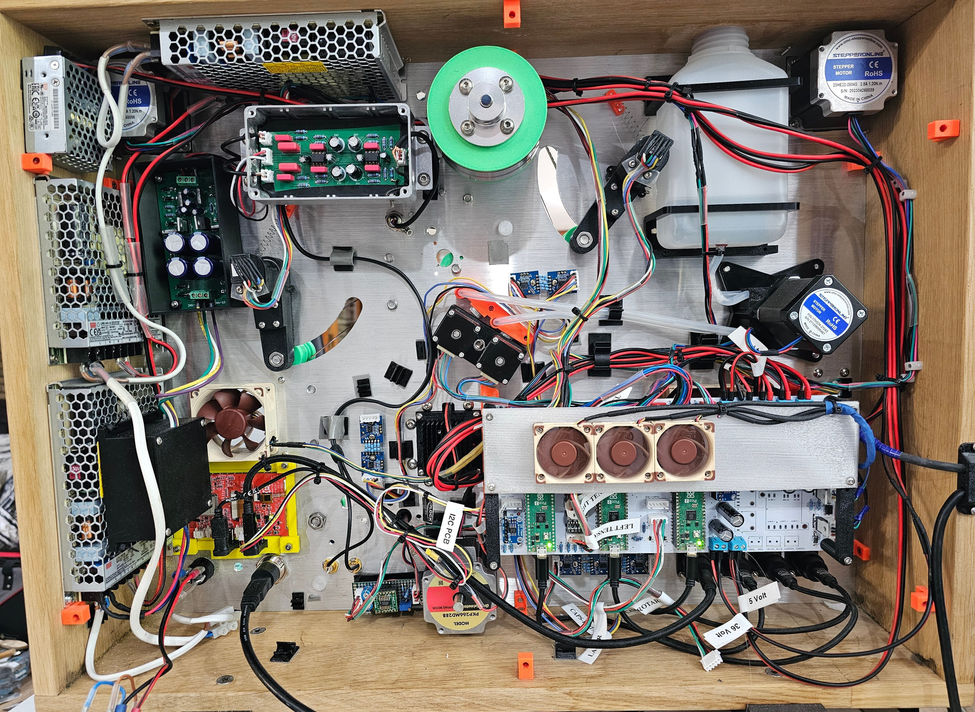
Can you share a picture of the back side and describe a bit of the transport?
If you are willing to share more info… some details that would help understand your project:

  • Type of motors
  • Details on tension sensing / control
  • Controller board used in the transport

Again, congratulations.

For anyone wishing to build it: drawings, material specifications, the scanner driver software, etc.

Here is sone more info regarding the scanner design:

CineScanner System Overview

The CineScanner is a real-time film digitizer for 8 mm, 9.5 mm and 16 mm film. It captures frames at 1K–4K resolution at up to 30 fps and is controlled from a Windows PC running CineMaster, which captures the video and audio streams.

This document describes the scanner’s electronic architecture in plain technical language.

System at a Glance

The scanner is built around a small network of microcontrollers that share the work across four logical roles:

  • User Interface & Master: ESP32-S3 with a 4" touchscreen; handles the Wi-Fi link to CineMaster and orchestrates the other controllers.
  • Reel Control: Raspberry Pi RP2350; handles tension control of the supply and take-up reels.
  • Film Transport / Capstan: Raspberry Pi RP2350; handles film movement, laser- and stepper-based image registration, LED light control and wet-gate cleaning.
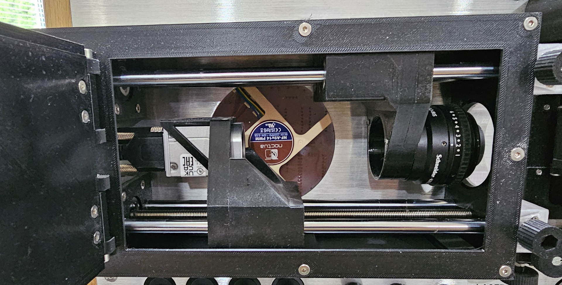
  • Optics / Utility: Raspberry Pi RP2350; handles the camera and lens sledges, focus, and the camera and wet-gate fans.

The three RP2350 boards are referred to internally as REEL, CAPS and UTIL. The ESP32-S3 is USER.

Inter-Controller Communication

All four controllers are connected on two shared I2C buses running at 400 kHz.

  • USER acts as the overall I2C master.
  • REEL, CAPS and UTIL are I2C slaves to USER.
  • CAPS acts as master for REEL during movement, using the second I2C bus.

A custom compressed command protocol carries configuration, status and motion commands (8-bit). Wide (16/32-bit) packets are supported for values such as absolute frame position, camera position and lens position.

The ESP32-S3 also exposes a Wi-Fi server so that CineMaster on the PC can send commands and read status, as well as a Bluetooth server for setting up the Wi-Fi network.

Motors and Motion Control

The scanner uses eight stepper motors.

  • Left reel - TMC5160 (REEL) Supply reel - NEMA 23

  • Right reel - TMC5160 (REEL) Take-up reel - NEMA 23

  • Capstan drive - TMC2209 (CAPS) Frame-accurate film transport - NEMA 23

  • Wet-gate cleaning wheels - TMC2209 (CAPS) Applies Isopropyl-alcohol during capture - 2Ă— NEMA 11

  • Wet-gate pump - TMC2209(CAPS) Isopropyl-alcohol pump, 2 channels NEMA 17

  • Camera sledge - TMC2209(UTIL) Moves camera and lens relative to the film plane - 2Ă— NEMA 11

Stepper Driver Details

  • TMC5160 (REEL): high-current SPI drivers, up to ~3 A RMS. They communicate over a software-SPI bus.

  • TMC2209 (CAPS, UTIL): UART-configurable drivers sharing a single-wire UART bus per board.

All drivers run in StealthChop for quiet operation during capture and can switch to Spread Cycle if more torque is needed. Stall Guard is used on the camera and lens sledges to find their mechanical home positions.

Reel Tension

Each reel arm has an EMS22A absolute rotary encoder. The encoder angle is translated into a relative tension value. A PID controller (or an optional ADRC controller) continuously adjusts the two reel steppers so that the film loop between the reels and the capstan stays at the correct tension.

Frame Registration

The CAPS board can register frames in two ways:

  • Mechanical registration: a tooth on the capstan generates an interrupt.
  • Laser registration: a laser/sensor detects sprocket holes and also generates an interrupt.

The method is selected via the registration configuration parameter.

User Interface

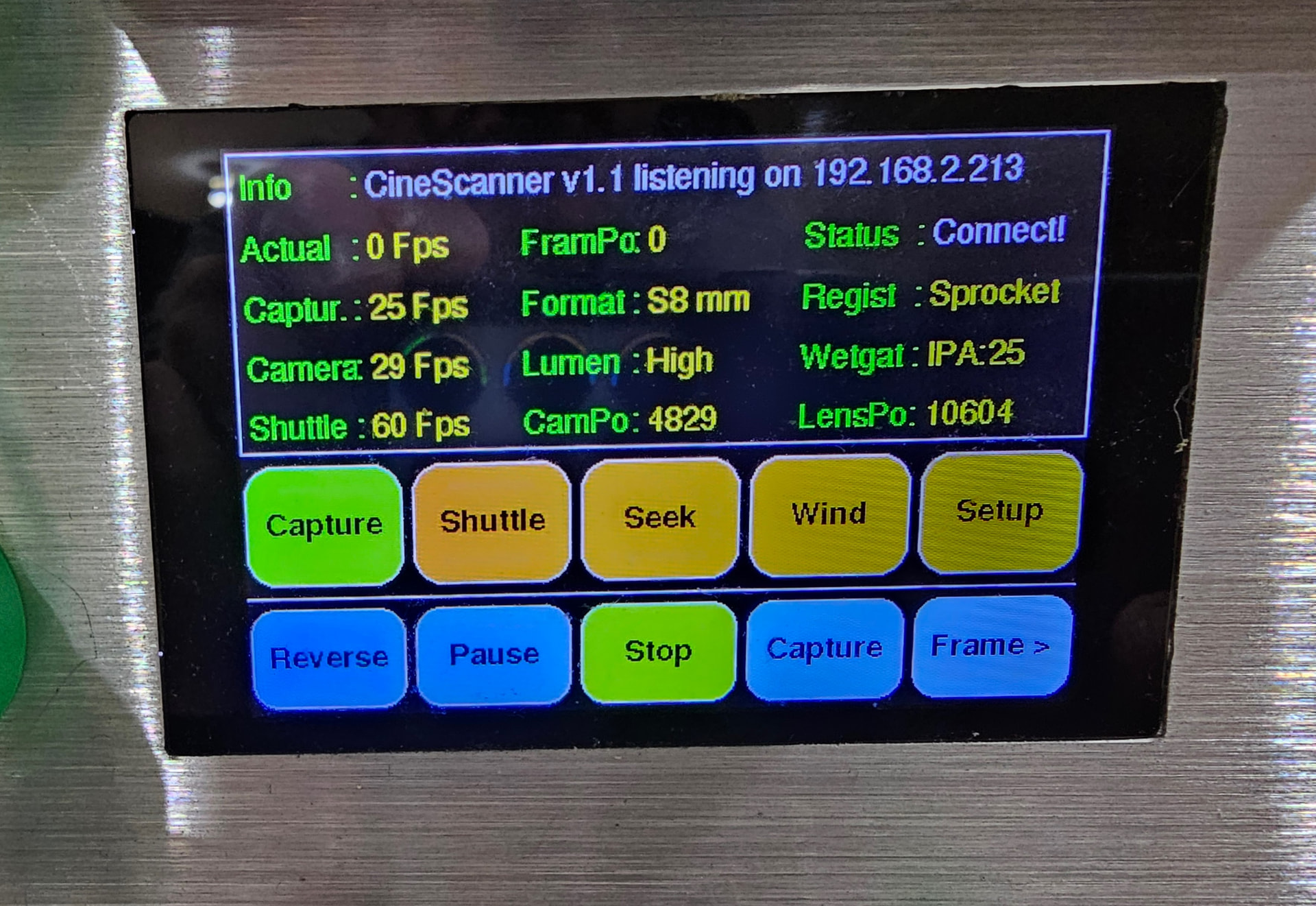
·4" TFT LCD with an ILI9488 controller.

·Driven by the ESP32-S3 over a 16-bit parallel bus at 20 MHz. Resolution: 320 × 480 pixels.

·FT6236 capacitive touch controller using I2C.

About 95% of the parameters can be modified from the scanner’s user interface. During film movement, the display shows frames processed, FPS, status messages, and key parameters.

Capture, shuttling, seeking, winding and setup can all be handled from the scanner’s user interface. Normally, however, once the scanner is connected to the PC app, the user interface is used only to show status. If the PC app disconnects, the scanner enters stop mode.

Lighting

Three CRI 98 LEDs illuminate the film during capture. Brightness is controlled by a DAC that, through an electronic switch, drives three LED drivers. During capture, these supply 1 A, 36 V pulses to each of the three LEDs in parallel. This arrangement allows the light output to be pulsed from 0 lumens up to 3000 lumens.

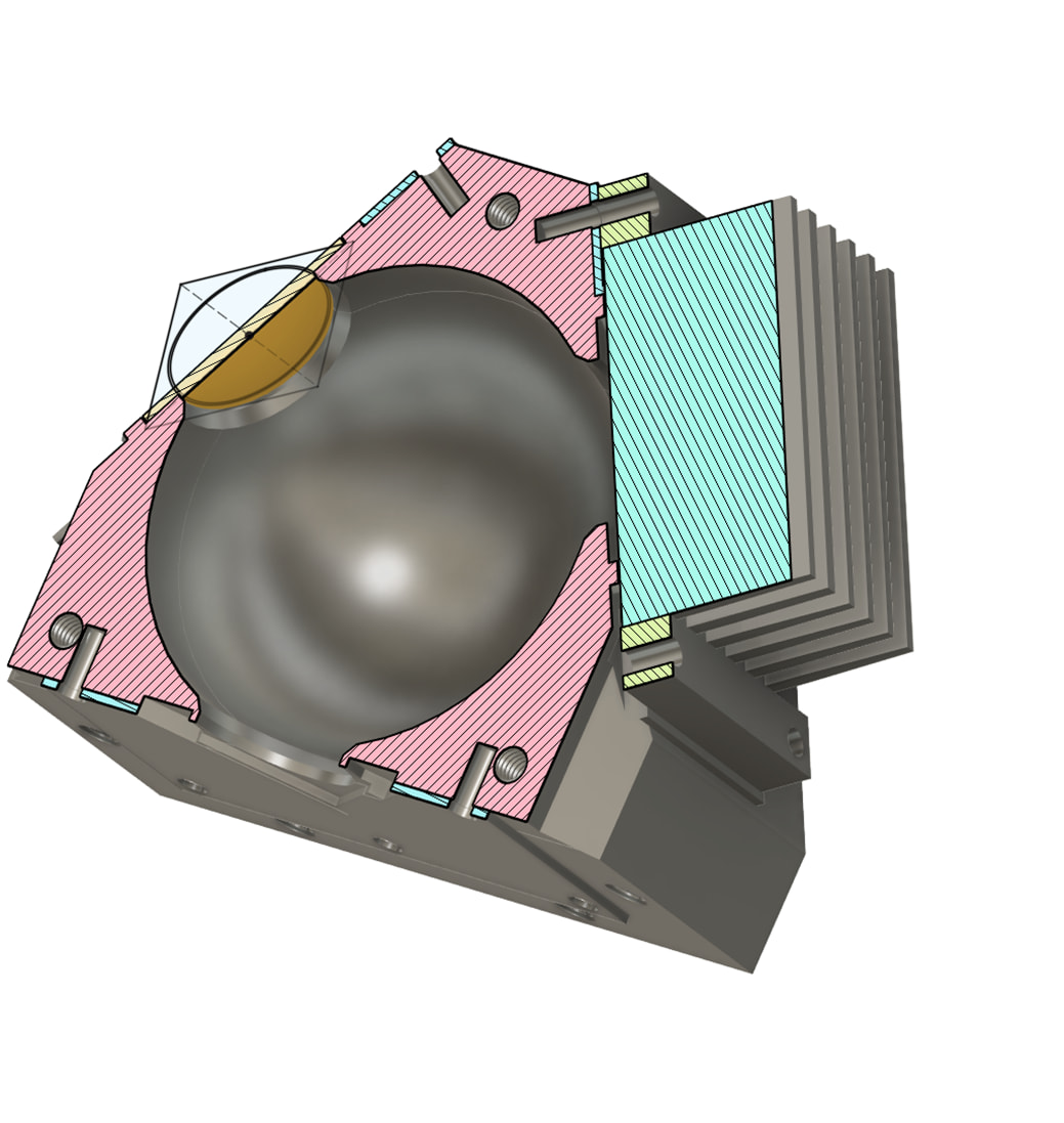
The 2 LEDS are mounted I a ball sphere, for light diffusion.

Camera Trigger

The CAPS controller generates the camera trigger signals:

  • Shot: tells the camera to capture a frame.
  • Pause: tells the PC app that the scanner is in pause (10 shots per second) or in stop mode.

Wet Gate System

The wet gate keeps the film clean and flat during scanning:

  • Cleaning wheels: apply isopropyl alcohol to the film. Each wheel turns opposite to the film direction, allowing the alcohol to distribute before it reaches the film.
  • Pump: meters the alcohol supply.
  • Dry fan: a drying chamber removes residual alcohol after cleaning.

All speeds are adjustable and are scaled by the current film speed or by manual settings.

Non-Volatile Storage

Configuration and calibrated positions are stored in FRAM (ferroelectric RAM) over I2C:

  • CAPS FRAM: all configuration except camera and lens positions.
  • UTIL FRAM: camera and lens positions.

FRAM is used because it is fast, wear-free and retains data without a battery.

Configuration is also stored in each project on the PC app, but the scanner remembers the last-used configuration so that it can be used stand-alone.

Software Architecture

Each RP2350 and the ESP32 runs on two cores:

  • Core 0: command handling, state machines, PID/ADRC loops, and I2C communication.
  • Core 1: stepper alarm interrupts, encoder polling, logging, and — on the ESP32 — Wi-Fi and Bluetooth.

A bespoke cooperative multitasking system schedules the tasks on each core (typically 5–15 tasks) in real time with 1 ms resolution, and also handles task interrupts for image acquisition.

A bespoke interrupt-driven stepper driver system controls up to 3 steppers (or optionally servos) per RP2350 at up to 60,000 steps per second, with exact RPM speeds and constant acceleration/deceleration. Stepper API calls are marshalled between the cores to avoid interrupt races.

I2C read and write communication is interrupt-driven and always runs on Core 0.

Control Loops

·Reel tension: the REEL main task runs every 1 ms; the rotary encoders are read every 2 ms; and the PID/ADRC loop runs every 5 ms, sending a speed adjustment to each reel to hold the set tension regardless of film speed.

Capstan speed: acceleration is profiled with an Austin-style stepper ramp; the frame rate is averaged over the last few samples.

Optics positioning: the thin-lens equation is used to keep focus while zooming between overscan modes and different film formats.

Sound

·Optical sound is extracted and decoded by the PC app in real time (not related to the scanner).

·Magnetic sound is captured by a magnetic head module (R8, S8, or 16 mm) located just after a 1 kg flywheel drum and just before the wet-gate applicator. The signal(s) from the magnetic head are amplified by a bespoke, flat-frequency, high-fidelity, 2-channel pre-amplifier (1 mV sensitivity). Customizable EQ is handled within the PC app. The analog signals from the pre-amplifier are fed into a USB audio interface of choice, which the PC app connects to in order to capture the sound.

5 Likes

This is truly an exceptional, professional-grade build. Although it will require considerable effort, we look forward to the gradual release of all construction details—3D prints, PCBs, electronic schematics, panel drawings, etc.

This is very impressive. The complexity is incredible — with the number of Teensy boards, the number of power supplies, and all the wiring. I realize how difficult it must have been to design all of this. Truly, bravo!

1 Like

The complexity and clean UI is amazing. Do you plan sharing how to build one of this so we can do one by ourselves? This is amazing Lars!!!

Can you share more of the scanner working? I know I am not the only one that would love to see it working. Cheers from Guatemala!

1 Like

It has been a large and quite complex project, and it would take a lot of effort to document everything so that it could be built by anybody. The source code consists of 60,000 lines of C code for the CineMaster app and 25,000 lines of C code for the scanner itself, plus several hundred 3D models and several PCBs/electronic circuits that need to be assembled and tested. But I’m happy to answer specific questions.

1 Like

We understand that this involves a fair amount of effort. Of course, we don’t need a code analysis; we just need the programs as they are. The 3D files, electronic drawings, and manufacturing files for your PCBs are also sufficient. Then, as you mentioned, someone can ask for clarification if needed.

1 Like

Congrats on the build. Looks quite impressive. Hope you get a lot of good results from this build.

All the best from a fellow Dane.

/Chris

Well, that’s a machine to be proud of! Amazing build.

what are the light fixtures used and how the light chamber operates? Hard to guess from picture.

also can you please clarify tension measurement and setting, I can see a spring, but how you manage variable tension in this system?

The integrating sphere houses three LEDs mounted in a triangular arrangement, each fitted with its own heatsink. The interior of the sphere is coated with barium sulphate paint.

Each LED is driven by a voltage-controlled constant current source capable of supplying up to 36V and 1A to each LED.. Light intensity is set via a microcontroller, which communicates with the CineMaster PC App over WiFi. The LEDs are switched on at a set level and off to capture each image..

While the film is moving, an interrupt to trigger image capture, which can be generated by either the bespoke stepper library or the laser circuit.

During shuttling or high-speed searching (up to 250 fps), frames are selectively skipped depending on the current fps setting.

Each tension arm is spring-loaded and drives an absolute encoder with a resolution of 1000 steps per revolution. As the arm moves, it outputs a value from 0 (no tension) to 185 (maximum tension). A dedicated PID controller for each tension arm regulates its corresponding reel stepper motor to maintain one of five fixed tension setpoints.

During capture, each reel stepper receives an updated speed command every 5 ms, in either direction as needed.

Before capture begins, tension must first be established by sending a pause command to the scanner. The scanner then sets the target tension and begins capturing images at 10 fps while the film is at standstill. In this standstill mode, the image center can be adjusted vertically, focus can be set automatically, imege can be zoommed in or out depending upen the wanted overscan. and the pressure plate can be closed if needed to flatten warped film.

Once capture starts, the capstan stepper advances the film while the closed-loop tension control systems on the left and right continuously adjust the reel stepper motor speeds. This system remains stable at frame rates up to 250 fps.

3 Likes

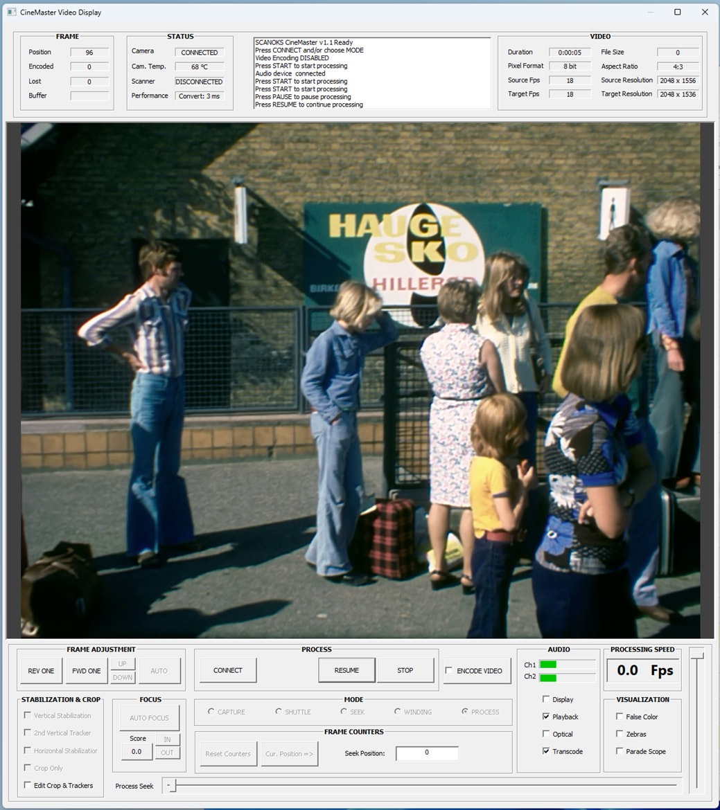
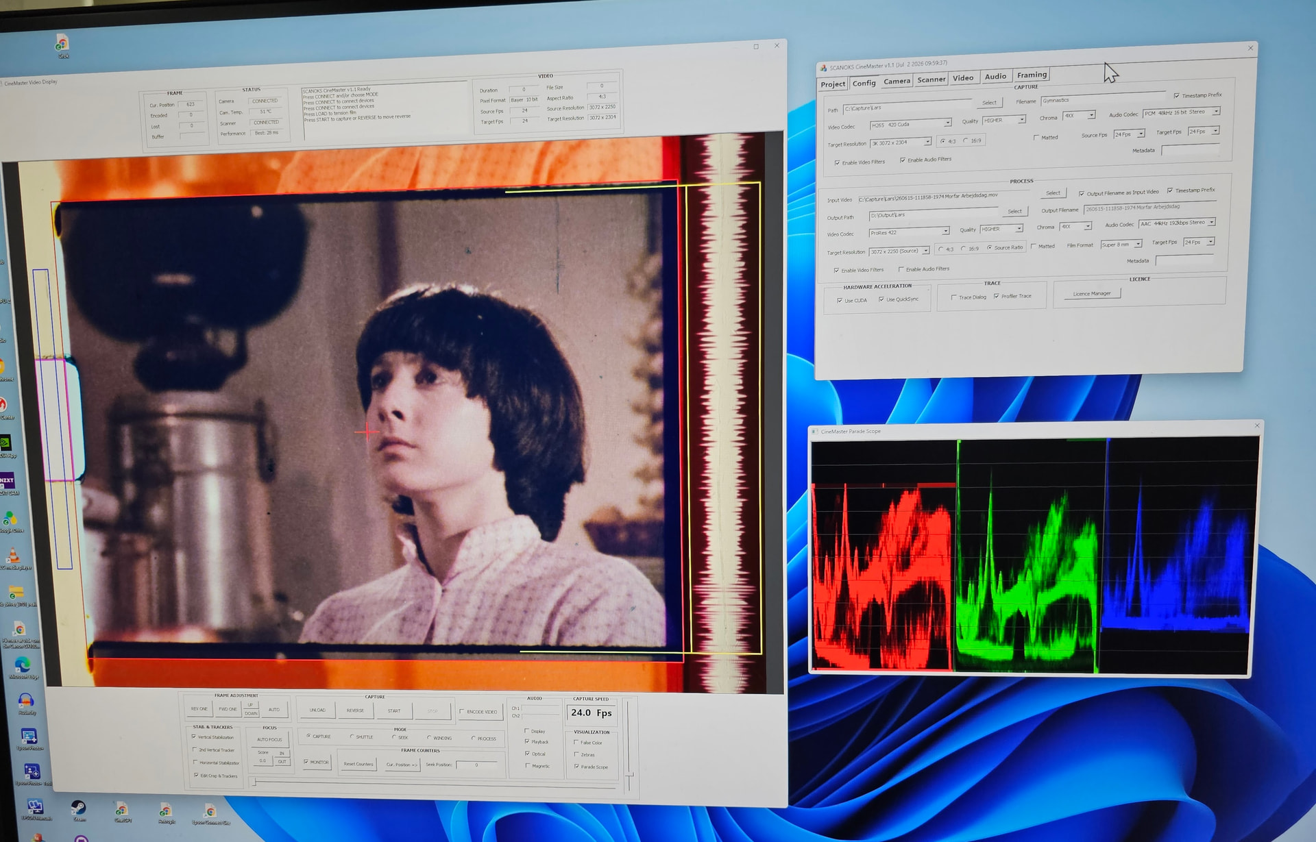
This is the main monitoring dialog, used for controlling the scanner and for post-processing captured video files. The top consists of various status fields, as well as a scrolling status window. The bottom section is the main control panel.

Frame Adjustments supports single-stepping the frame one frame at a time (“Rev One”, “Fwd”) and centering the frame (“Up”/“Down” and “Auto”).

Stabilization & Crop controls the setup of the trackers needed for vertical and/or horizontal tracking and stabilization, typically by using the sprocket(s). When “Edit Crop & Tracker” is checked, the monitor window shows the uncropped image and the checked trackers, and optionally the optical track (one or two) if the “Optical” checkbox under “Audio” is checked. In Process mode, “Crop Only” allows cropping of the image with no stabilization—for example, if a capture with overscan needs to be framed.

Focus controls the camera focusing. “Auto Focus” starts the focusing process, finding the optimal focus for the current camera position. A focus score is shown overlaid on screen as well as in the score field. “Auto Focus” is only enabled when the film transport is stopped. Pressing the score field briefly shows the current focus score. For manual adjustment, “In” and “Out” move the lens one step at a time while updating the focus score.

The Top Center area contains 4 buttons that change depending on the selected mode. The first button establishes the connection to the camera, scanner, and audio interface. Once a connection is established, the button changes to “Load”, allowing the film to be tensioned. When tension is established, the button shows “Unload”, which allows the film to be de-tensioned.

In Capture mode, the next 3 buttons are “Reverse”, “Start”, and “Stop”. “Start” moves the film forward and starts capture if “Encode Video” is checked. “Reverse” moves the film in reverse. The vertical slider on the far right allows the fps to be varied between 1 fps and the maximum fps the camera supports at the selected resolution.

When capturing magnetic audio, the “Magnetic” checkbox must be checked; if “Playback” is checked, monitoring is enabled. When “Magnetic” or “Optical” is checked, the capture fps is fixed to the speed defined in the “Config” tab dialog—typically 18 fps for Super 8 and 24 fps for 16 mm. When capturing is in progress, “Audio” opens a window showing the audio of the two channels scrolling from right to left. Under **Visualization**, “False Color”, “Zebras”, and “Parade Scope” facilitate analysis of the image exposure and color balance.

When capturing, the “Start” button changes to “Pause”, which allows the capture to be paused and resumed. This is not recommended for magnetic audio, as the audio will be distorted when decelerating and accelerating (“resume”). If “Stop” is pressed during capture, the film transport decelerates to a stop and the video file is closed.

In Shuttle mode, the 3 buttons show “Reverse”, “Forward”, and “Stop”. Pressing “Forward” (or “Reverse”) shuttles the film forward (or reverse) at the fps set by the slider on the far right, which can be varied between 1 and 250 fps. Shuttling at very high speeds is not recommended when the film is threaded for magnetic audio, as the magnetic head gets worn. While shuttling, the stabilized image is shown in the center at all times.

In Seek mode, the film and frame can be moved to a stored frame, or to a specific frame number or time, using the set shuttle speed.

In Winding mode, the 3 buttons are “Reverse” to rewind, “Forward” to wind, and “Stop” to stop the winding. The RPM can be regulated with the far-right vertical slider.

In Process mode, captured and generated videos can be played back and manipulated. All the same features available in Capture mode are supported in Process mode, but transcoding is normally much faster than capture speed. Up to 500 fps is possible for lower resolutions with CUDA. While showing/transcoding a video, audio can also be monitored when “Playback” is checked. If “Playback” is not checked, the monitoring/transcoding runs at maximum speed. “Pause”/“Resume” is supported while monitoring/transcoding. Shuttling in Process mode is supported when monitoring and “Pause” is selected; using the large horizontal slider at the bottom, the playback frame can be moved from 1 to the maximum number of frames in the video file.

The Video Display dialog can be resized, and the video area is resized according to the set aspect ratio. The size and position of the dialog are remembered as part of the active project configuration.


-

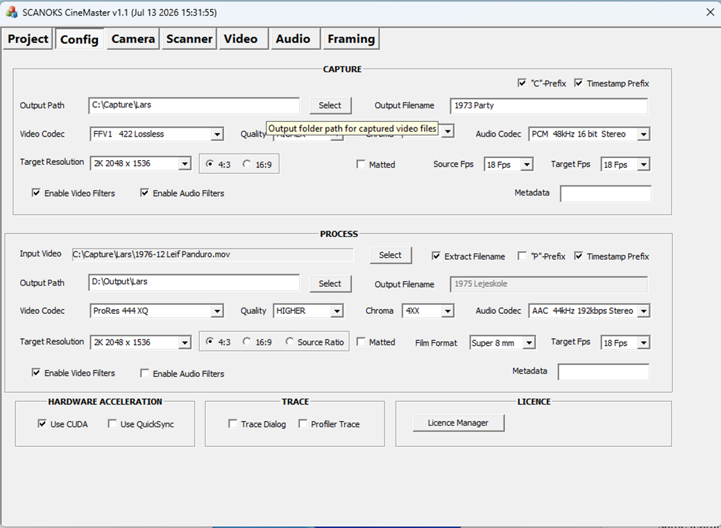
The tab dialogs looks like this. To be described at a later time. “Framing” is for testing and will be removed.

2 Likes

Dear Lars,

thank you for sharing those, it’s really inspiring and helps to focus the logic of any machine in comparison.

With that amount of work you’ve applied while making this one I’m quite sure you can successfully scale it up to commercial level if needed.

One question though, have you ever considered using RGB illumination and scanning with narrow band lighting? If no then it’s interesting to listen the reasons why.

When using my scanner system, if I encounter a feature that doesn’t work as expected, or if I think image or sound quality can be improved, I will try to improve the feature where financially and technically feasible. I have prepared the electronics for individually controlled Red, Green, and Blue LEDs as a supplement to the 3 white LEDs. I have not yet seen the white LEDs as limiting image quality, but this might be the case for badly faded film (which I don’t have access to).Do you think that I will see an improvement when using RGB LED’s for non-faded film ?

my expertise with film scanning arrives from Production background, rather than engineering one. I’ve been testing huge amount of light sources to scan still film images before building my own motion film machine and trying to apply this knowledge. With still images, having calibrated narrow band lighting returns significantly better color separation of scans even using regular color Bayer sensors. With RGB - Cineon pipeline conversion works way more stable and predictable, and provides more intuitive and straightforward logic for Colorists to align footage captured this way with industry standard machines like ARRISCAN (which uses RGB). My own set of experiments on motion picture with white lights and narrow band lights returned significantly better color improvement. I’m using different light blocks for negative film stock (RGB), 3000K white light for positive film stock (to imitate projector head) and either of two for black and white. Not really sure which way works the best, but I feel like RGB returns way more control in post production.

i could go more into details, but I feel like this paper describes everything way better already - GitHub - jackw01/scanlight: A better light source for scanning color negative film · GitHub

@Andriy_But I think the context is fundamental on making the comparison.

  • Non-reversal (negative) film (as the article you linked)
  • Spectral quality of the white LED
  • Camera or Sensor Response
  • IR filter response

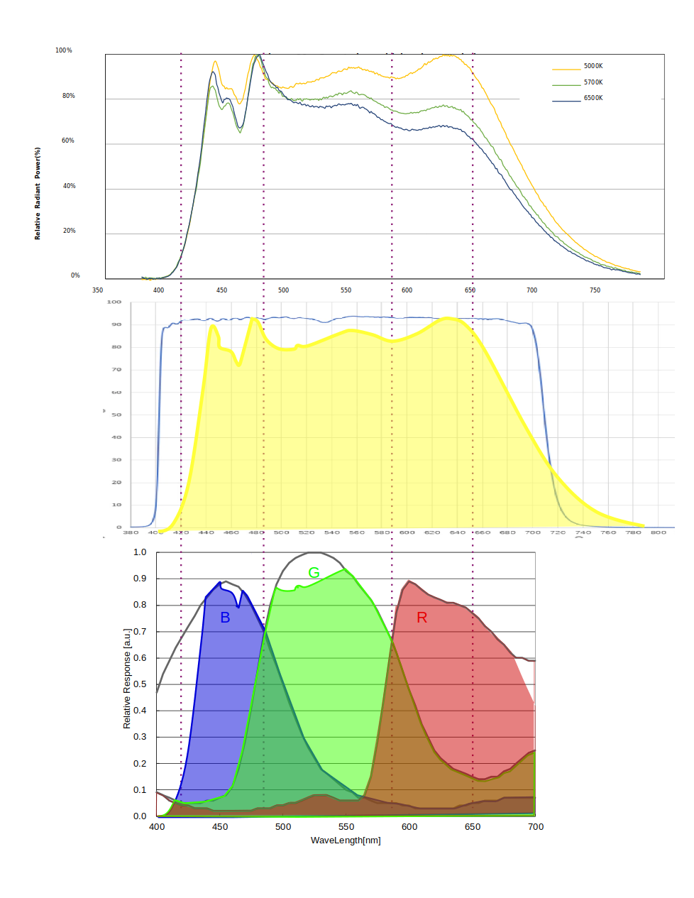
To illustrate the HQ sensor response is not too bad for 650-700 nm (compare with the linked sensor sensitivity, but at the same time, the factory IR filter it uses leaves most of the band out.

I removed the factory IR. For comparison (same sensor as above), using a 5100K fairly flat LED, an external IR-UV, the red is quite broader. And it certainly should help the Cyan separation in a negative film (I am actually looking for good reference negative, if someone is willing to share a couple of feed of well shot Super8 or 16mm).

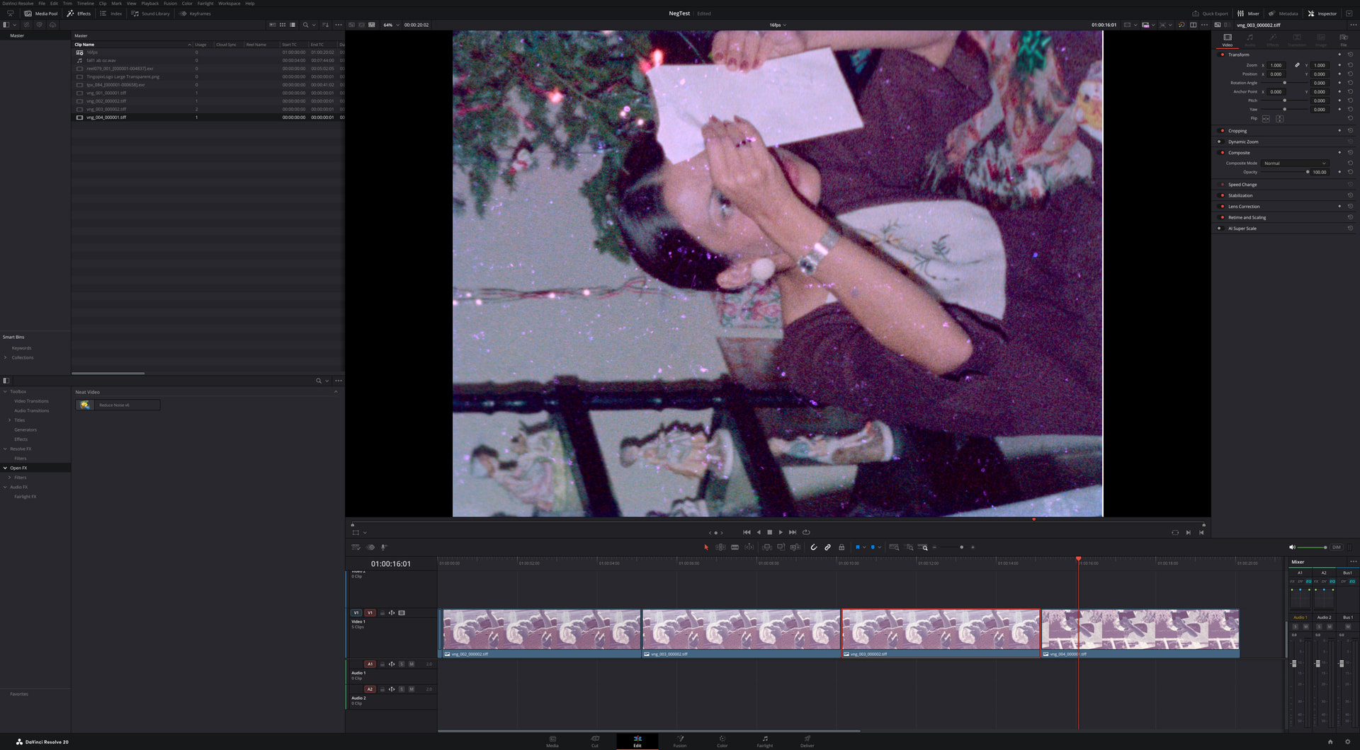
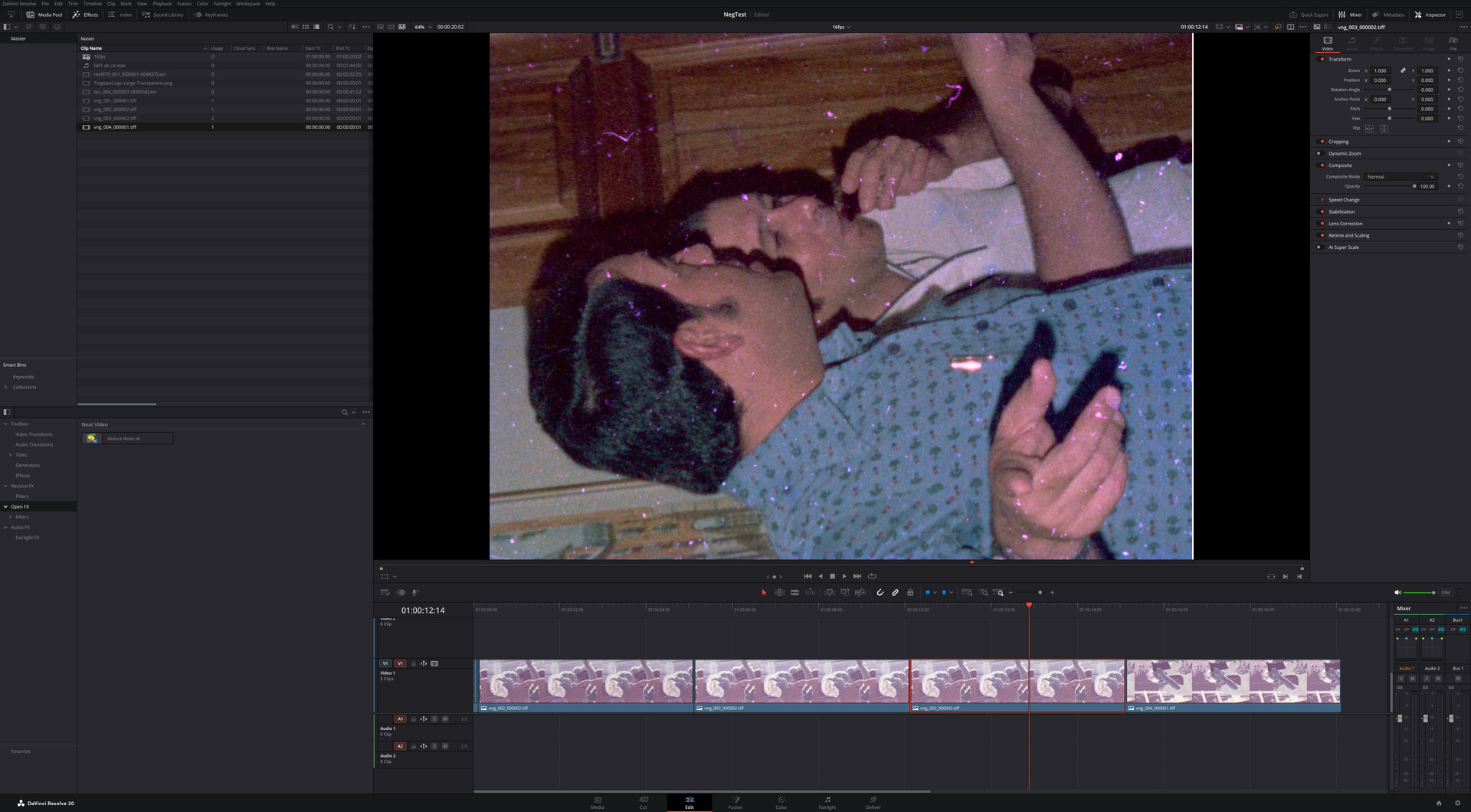
Here is a 110 photo negative from the 70s scanned with the above setup, color corrected in Resolve for a quick test.


Thanks both, this is really useful.

@Andriy_But — appreciate the real-world workflow context. The Cineon/RGB pipeline point about aligning with ARRISCAN-style colorist workflows makes sense as a separate benefit from raw color separation — that’s a post-production/interop argument, not just an image-quality one.

I read through the scanlight article in detail, and the core physical argument is more specific than “RGB looks better”: with C-41 negative, the orange mask lets a lot of yellow-orange light through mostly unabsorbed by any dye layer, and that light lands right where a Bayer sensor’s red and green channels overlap. So under white light, the red channel picks up crosstalk from the magenta dye layer too, and the green channel picks up all three layers — which is why negative conversion needs dedicated software rather than a simple invert. Narrowband light tuned to avoid those overlaps apparently gets you close to a straight channel swap. Their suggested targets are >650nm red, 520–550nm green, <450nm blue — narrower than generic RGB LED strips (620–630/460–480nm), so not just any RGB source gets the full benefit.

Interesting side note: the article also argues broadband white light is preferable for positive/reversal stock, and that narrowband tends to oversaturate and hurt skin tones there — which lines up with what I’m already doing (3000K white for positive to match the projector-lamp look, separate path for negative).

@PM490 — good to isolate sensor/IR-filter response as its own variable. My CRI98 white LEDs are broadband, not the 5100K flat source you tested, so I can’t map your IMX477 results directly, but the general point stands: a narrowband red LED’s benefit still depends on how much of that band actually survives the optical path to the sensor.

Since I already have individually-addressable R/G/B electronics wired in alongside the three white LEDs, the concrete next step for me is to pick LEDs closer to the recommended wavelengths (not just generic RGB) and scan again under both my current white source and the new RGB block, to see if there’s a visible difference outside the faded-film case I originally asked about.

1 Like