CineScanner / CineMaster completed

Thanks @Lars_Oksbjerre.
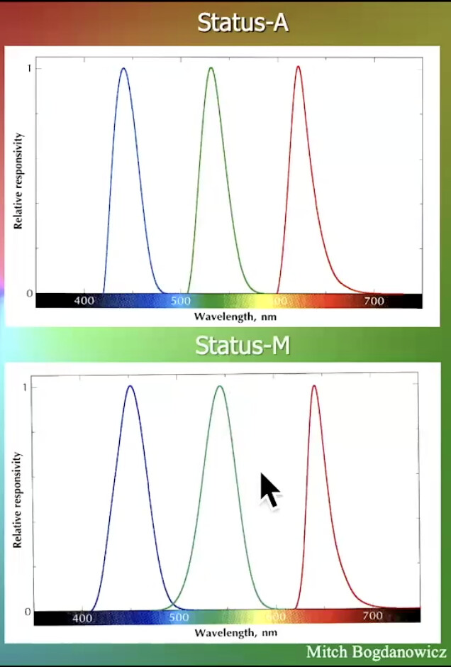
For clarity, the graphic above is an illustration superposition, not the actual output. Also I mistakenly wrote 5100K, the LED is actually 5000K.
Here the specs for the one I use.

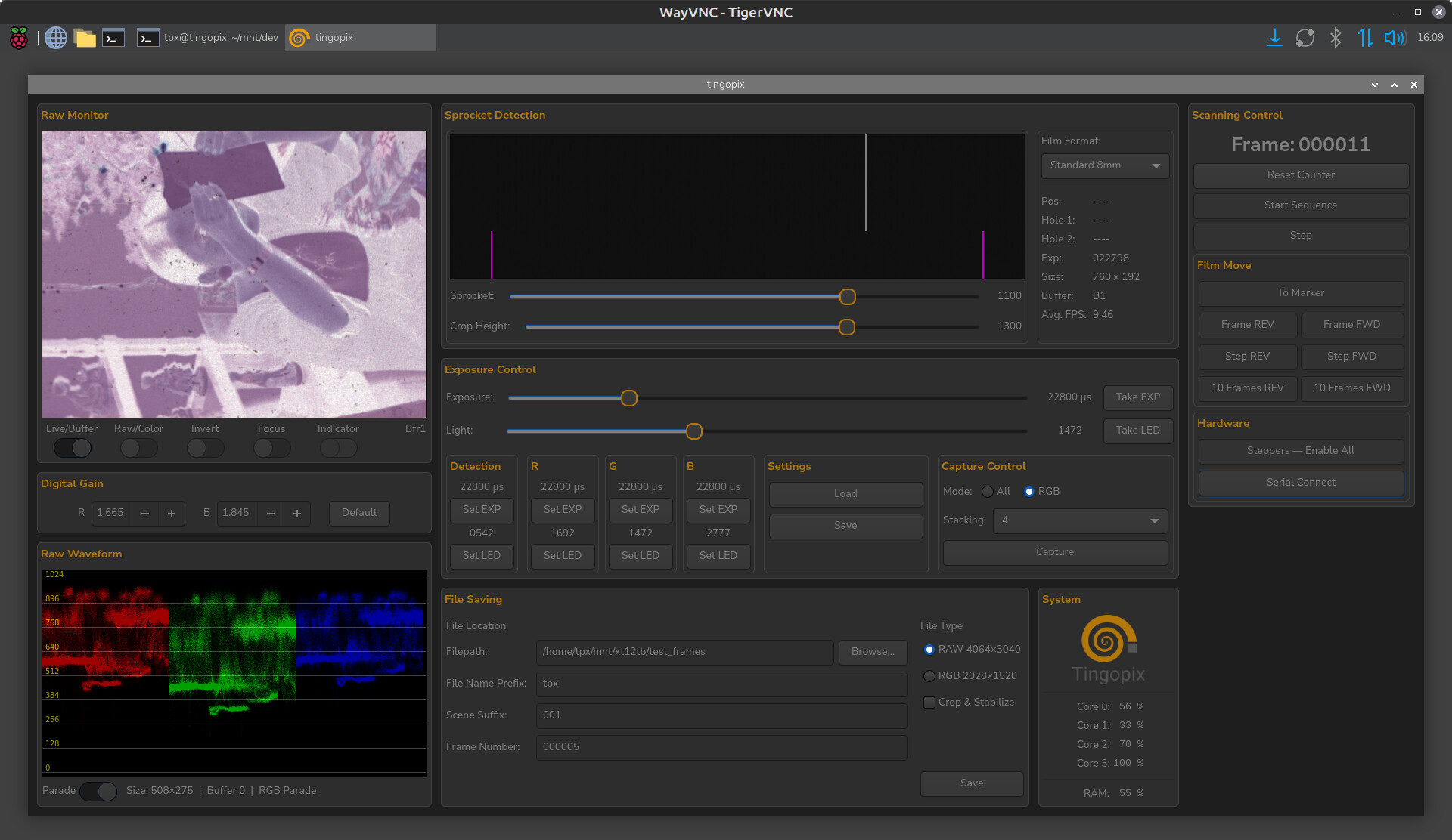
My setup stops to capture at every frame, so less light intensity is generally required. Stopping the frame for capture also gives one the ability to capture each color channel (R G and B) at a different light setting, separately. The above tests were captured with separate color intensity, hence the similar levels at the waveform monitor.

Absolutely valid and I understand that most of the scanning jobs with archival images or footage shot by amateur users would require much less accuracy in conversion. I’m oddly satisfied with conversion algorithms designed for negative stock by different names in the industry. They look great to eye. The problem however is when professional colorists start to operate this footage it appears that known tools designed for Cineon conversion process start to fail miserably as initial capture methods already manipulate the curves before they were sequenced into ProRes.

Also worth mentioning that COLORS are highly subjective and people who master the actual images output are doing way more than just fine tuning pleasing image. With that said having baseline that is predictable and prone to errors in conversion process (which Cineon was designed for) is much more preferable. I can output Cineon gamma from any image sequence, but it won’t be the thing everybody expects from it.

Meanwhile most users will ask to provide a viewing LUT at least if they see raw scans, just because baseline Cineon would not give you anything pleasing to your eye. This is a culprit for broad audience, but why then every professional machine for cinema quality work does exactly that?

p.s. I’ve designed custom PCB broadband lights based of Cree XP E2 fixtures of specific wavelengths (Photo Red, Royal Blue, Green) and I’m insanely happy with how images behave. Even when scanning is only one flash capture (balanced to the sensor output though).

1 Like

Speaking about faded films I feel like it’s more tricky. We should take into account the actual type of the stock we’re talking about. Faded dyes shift significantly and Vision3 would behave differently than EXR stocks or even older ones, because of the amount of cross influence between different dyes.

Additionally worth mentioning that responsiveness of negative film stock differs from channel to channel, so it requires less of Green light and more of Red light to be present and it can be tuned either by applying less current to specific strips or with just less amount of LEDs itself.
Also I’ve seen @fabriccio was using different wavelengths of red on a single PCB to use specific reds based on the film stock (positive vs negative)

1 Like

Faded dyes shift significantly and Vision3 would behave differently than EXR stocks or even older ones, because of the amount of cross influence between different dyes.

In my experience, having scanned millions of feet of film, this is a non-issue. The only film that really fades is positive, and typically print at that (though there is some reversal that fades too). Negative just doesn’t, really. Some older color neg stocks look “faded” by modern standards but they’re really not, that’s just how they look. Thinking like 1980s Kodak color neg, pre-Vision series.They’re pretty washed out with lifeless color and chunky grain, and always were.

3 Likes

Dear @Lars_Oksbjerre

If that’s acceptable, can you please provide some additional details on tension balancing system of your machine? I’ve started assembling similar one and trying to wrap my head aroung the concept itself. You’ve mentioned that on load state the motors are calibrating somehow (I assume both motors trying to fix the position of dancing arms in specific state) and how then transport is working? Then when capstan starts pushing the film, does it communicates with reel motors somehow, or they constantly readjust tension without backfeed?

The scanner has four SBCs:

  • USER handles the touchscreen, WiFi, CineMaster, and communication with the other boards.
  • CAPS controls the capstan motor, film transport, camera, the 3 wet gate motors, and REEL.
  • REEL controls the two reel motors and film tension.
  • UTIL controls the camera and lens motors, and the 5 fans.

Film tension and transport

There is a clear difference between Pause and Stop.

Pause stops the capstan but keeps the film loaded and tensioned. This allows the scanner to start again without creating a slack loop.

Stop releases the tension. The reels unwind until the film is slack, then the motors are disabled.

Each reel has a dancer arm with an encoder. The encoder position is used to control tension. The UI provides a target value from 0 to 184. A low value means the film is slack, while values near the limits indicate too much or too little tension.

During Pause, REEL moves the reels until both dancer arms reach the selected target. If the film becomes slack, REEL takes up the slack again. If it is too tight, the reel pays film out. When both arms are close to the target, the motors stop and the film is marked as tensioned.

The PID/ADRC control loop used while the film is moving is not used during Pause. During Pause, the reels simply make small corrections to keep the dancer arms at the setpoint.

De-tensioning uses a target of 0. The reels pay out film until the arms reach the slack position, then the motors are disabled and the tensioned flag is cleared.

Capture and shuttle cannot start unless REEL reports that the film is tensioned.

Tension while moving

The capstan controls film speed. The reels do not control FPS. Instead, they continuously adjust their speed to keep the dancer arms at the selected tension.

Each reel has its own PID/ADRC controller. It reads the dancer position and adjusts motor speed, with the maximum RPM limited according to the current film speed.

In forward motion, the right reel is the take-up reel and the left reel is the supply reel. In reverse, their roles are swapped and both motors reverse direction. The controllers also change their correction direction.

The scanner does not need to de-tension before reversing. CAPS slows the capstan, REEL changes direction and retunes its controllers, and the film then runs in the opposite direction while maintaining tension.

Capture and shuttle

Capture uses slower reel speeds and fine microstepping for smoother and quieter operation. Once the target speed is reached, the tension control is softened to reduce film flutter.

Shuttle uses higher reel speeds and coarser microstepping. The reels still follow the capstan and maintain tension.

If an arm reaches the maximum-tension limit, or tension drops below the minimum limit, REEL stops the reels and reports a fault. A loss of tension can, for example, indicate a broken film splice.

CAPS and REEL communication

CAPS is the I2C master and REEL is the slave on their dedicated bus. REEL does not call CAPS; it waits for commands and provides status when CAPS reads it.

CAPS mainly sends drive commands:

  • Pause: tension and hold the film.
  • Stop: de-tension and disable the motors.
  • Forward/reverse/shuttle: follow the capstan while maintaining tension.

Before starting, CAPS checks the REEL tensioned flag. If the film is not tensioned, movement is refused.

CAPS also sends the actual film speed. A speed of 0 means the capstan is accelerating, so REEL uses firmer tension control. Once the target FPS is reached, REEL softens the control.

While running, CAPS checks REEL for motor faults. A reel motor fault causes an emergency stop of the capstan to prevent the film being pulled against a failed reel.

USER role

USER is the main controller between the operator, CineMaster, and the sbc boards.

CineMaster connects to USER over WiFi using TCP. Only commands and status information are sent over WiFi; video uses a separate connection.

In normal use, USER receives the operator or CineMaster command and sends it to the correct board.

For example, when Pause is pressed, USER tells CAPS to pause. CAPS stops the capstan and tells REEL to tension the film. Once REEL reports tensioned, the scanner is ready to run.

When Forward is pressed, CAPS checks the tension, starts the capstan, and tells REEL to follow it. When Stop is pressed, CAPS slows the capstan and tells REEL to de-tension.

In simple terms, USER coordinates the system, CAPS controls film transport, and REEL controls the reels and tension.

PID/ADRC controllers.

The system uses one PID (OR ADRC) controller per reel motor. The Controllers are recalculating at an interval of 5ms, the two absolute encoders are polled at an interval of 4ms. Due to the physical characteristics of the system—including spring tension, the weight of the dancer assembly, film-reel mass and diameter (which changes throughout the run), film speed and acceleration, reel motor target speed. Acceleration and deadband, tension deadband, effects on magnetic sound flutter — the system has been difficult to tune. At lot of trial and error has been required.

The system is currently using a single PID parameter set that has been tuned to provide stable and reliable performance across all of these scenarios:

#define Scan_Kp 0.55f

#define Scan_Ki 0.7f

#define Scan_Kd 0.1f

The PID implementation supports switching between different parameter sets depending on the operating conditions. However, this functionality is not currently being used, as extensive testing and tuning have shown that a single parameter set provides satisfactory performance across the required operating range.

An ADRC (Active Disturbance Rejection Control) implementation has also been developed as an alternative to the PID controller. While ADRC performs reasonably well, it has not achieved the same level of performance as the PID implementation, but it was much easier to tune. I am also more confident in the PID solution, given the amount of testing and tuning that has been performed on it.

The current ADRC parameters are:

#define ADRC_b0 250.0f

#define ADRC_wc 9.0f

#define ADRC_wo 15.0f
2 Likes

Dear Lars,

Congratulations on completing the CineScanner project! If you’re looking for more information about the ARRISCAN XT workflow, this website might be helpful:The ARRI Companion to Digital Intermediate

3 Likes

Could you perhaps upload the 3d cad or print files for the camera/lens servo

mechanism?

1 Like

As mentioned before, I am happy to answer specific questions.

1 Like

Thank you for your answer. I think I was clear. Could you upload the cad files or the files for 3d printing of parts for focusing system? It is a good system. If not doesn’t matter.

Curious if we could get a demo and some closer up shots of your wetgate contraption.

He will not share anything. I have tried and nothing specific is shared. I believe this is just a thread to show up the project, not for others to replicate it.

1 Like

I will produce a demo and some close up shots shortly.

2 Likes

As stated before, due the the effort required, I do not intend to produce a DYI kit for you to reproduce the scanner and its software. But will be happy to share design outlines of the systems.

1 Like

It’s a shame because you build looks super solid

1 Like

@fabriccio Why would it be?
Respectfully, it is a lot of work to design and built… But documenting a design for others, is no simple task. Give it a try! looking forward to see what you share in the future.

1 Like

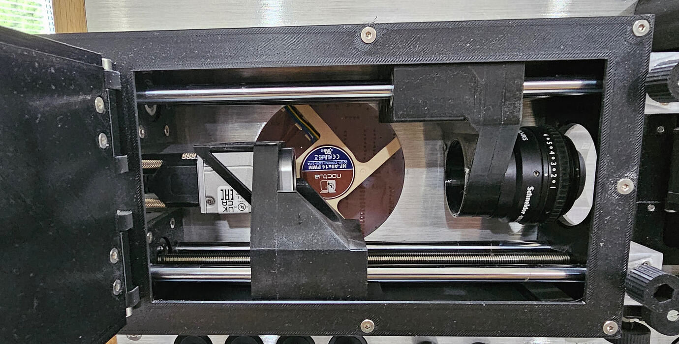
I don’t know why you’re approaching this issue in such a manner, even your description of Sasquatch assembly has design thoughts but no documentation or anything to replicate similar machine. We’re community that could reverse engineer based on design ideas shown here by different authors. I’ve used @fabriccio approach to LED PCB in my machine and incorporated camera/lens gantry based on @Lars_Oksbjerre idea. Some people are eager to share their CAD models, some people are not. It’s a personal matter. Though I can agree that this machine looks stellar.

1 Like