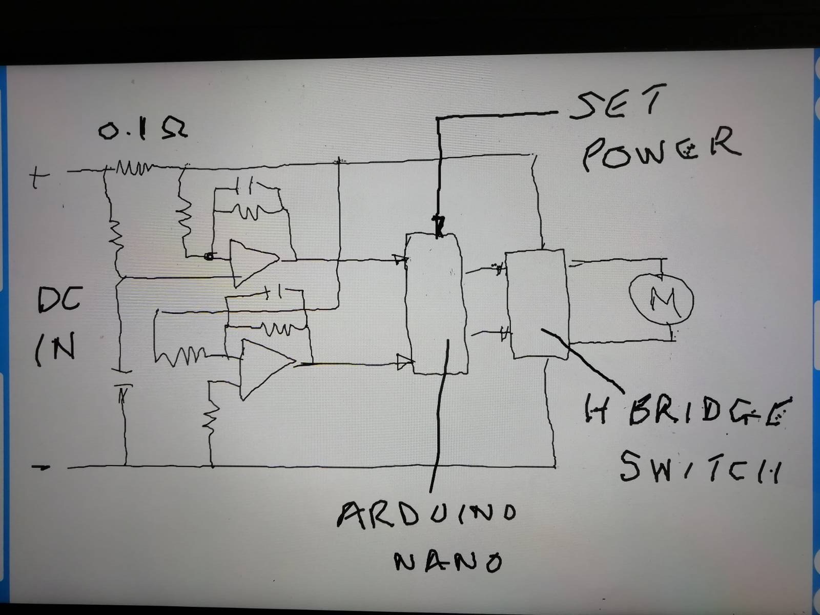
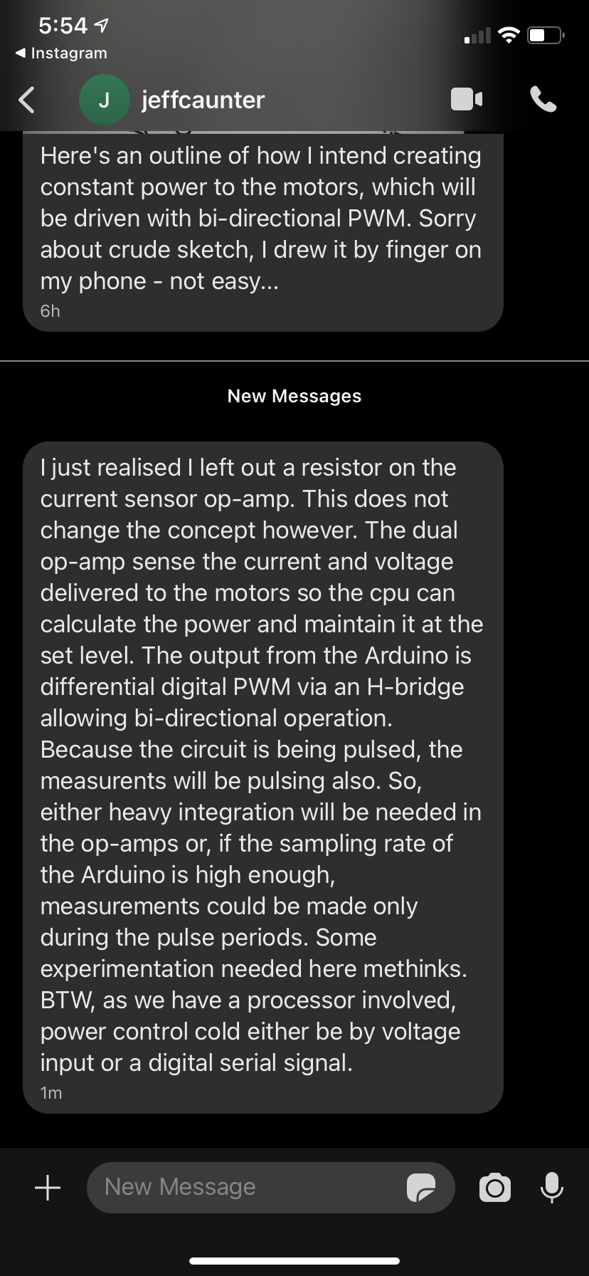
Here’s details of the discussion I had with Matthew to which he refers.
Firstly, let’s answer the question - why drive the motors with a controlled power rather than a controlled voltage (or current). There is only one answer - to eliminate the effect of the changing radius of the film on the reel(s) from upsetting the required tension or speed of the film that is being maintained by various external sensors and control loops. These changes in radius may be due to the natural effects of winding the film on or off their reels, or an eccentricity in the bulk of film in one, or both of the reels. This is not uncommon.
Secondly, by 'constant power ’ we are not implying that the drive power cannot be changed. It is essential that power levels to the motors can be dynamically adjusted to achieve the required tension and film speed but, once set, it is the job of the constant power driver to maintain these settings regardless of how much film is on each reel. The tasks of setting and stabilising the film speed and tension is down to the control loops associated with each motor, each having their own appropriate sensors. The constant power circuitry plays no part in this - it merely obeys the demands from the control loops in a very assistive way.
PROOF OF CONCEPT
From the law of rotary motion, the power required to rotate a body against an applied torque is -
Power = Angular Speed * Applied Torque ------------------ Eqn1
The film will be moving at a certain Linear Speed, so we have to convert this to Angular Speed which involves knowing the Radius of the film on the reel.
Angular Speed = Linear Speed / (2 * PI * Radius) ------- Eqn2
Looking firstly at the supply-reel, where constant tension is required, and assuming the film’s Linear Speed is constant (controlled by the take-up motor) …
Torque = Tension * Radius (of the film on the reel) ----- Eqn3
Combining Eqn1, Eqn2, and Eqn3 we get -
Power = Linear Speed * Tension * Radius / (2 * PI * Radius) - Eqn4
Now for the magic result - Because the Radius appears on both top and bottom of the equation they cancel out. Also, because we assumed the Linear Speed to be constant, and 2*PI is certainly constant, we can say :
TENSION IS PROPORTIONAL TO POWER. There are no other factors involved.
If the same approach is applied to the take-up motor, this time assuming the Tension to be constant, we find that :
LINEAR SPEED IS PROPORTIONAL TO POWER, with no other factors involved.
THESE TWO RELATIONSHIPS ARE THE KEY TO CREATING A PRECISE FILM TRANSPORT - it means the control loops only have to compensate for minor changes in the film path, such as scraping the edges of the reels or the passage of a splice through the gate.
It is tempting to think that if the power to the two motors have been adjusted for required tension and film speed that these will remain constant without any need for sensors or control loops. If only that was true - unfortunately neither of the motors knows anything about what they are controlling and do not provide a converging condition. The result is that the transport will ultimately either slow to a halt with high tension, or run at high speed with virtually zero tension.
So, it is essential that that at least one control loop is used to stabilise either tension or speed or both (two loops).
TO BE CONTINUED…