Design Sprint II - "Motorin"

Today is the beginning of a new Design Sprint. We have 2 weeks to improve the motor design for the take-up and supply reels.

Add your ideas in this thread and let’s see what we can come up with!

Also, if you’re new, head on over to the home page of the forums and read the “How to use the forums” and “Introduce yourself” topics.

Details on frame design, for reference are here: The Frame | Kinograph Wiki

Also see this follow up vid of you’re wondering what the back of that panel looks like so you can design accordingly. https://www.instagram.com/p/B_7cal3pvQW/?igshid=lt8lugq7kyhk

I think the tension units are a great design. Matched with a good motor and some electronics, you will be able to control the tension of the film quite nicely. Depending on the software, I think it should be even possible to adapt the tension for fragile films.

Decoupling reel axis and motor via a belt drive will allow other builders to try out and use alternative motors - a specific motor model might not be available or difficult to source in other parts of the world.

The same point can be made for the more complicated gear options you mentioned in the video - that specifc planetary gear or worm drive migth be very difficult to source at some places around the world. If you stick for the design to stuff which comes out of a massmarket product (scooter, 3D-printers, etc), chances are that it can be sourced for a resonable price at many places.

From my experience with old Super-8 projectors which did use a friction drive, I would suggest to stay away from that idea: it’s a common point of failure of these projectors after some usage. The surfaces which define the friction drive deteriorate over time or at least change their properties during usage; you might need to adjust them after some heavy use.

1 Like

Here are the results from the first round of tests. I could use some help weighing pros/cons of each. I would love to get suggestions for other motors/drivetrains to try!

Videos of these first three can be found on the Kinograph instagram account: Matthew Epler (@kinograph.cc) • Instagram photos and videos

Motor1: $41 + shipping.
Pros: there are tons of these motors available and they’re cheap. Plenty of torque.
Cons: heavy (passes cost on to buyer of Kinograph), awkward to mount
Overall: I think it’s more than we need. I’m looking forward to testing this one, which has less power output but is likely to be lighter and looks easier to mount.

Motor2: $70
Pros: tiny motor with a far lesser torque requirement
Cons: may require some kind of braking mechanism (or I could just ramp down quickly with the PWM signal?), cost but there’s likely a cheaper alternative. Anyone have an idea where I could look?

Motor3: ServoCity custom wormgear, ~$45
motor
gears
Pros: breaking is built in with the worm gear, lesser torque requirement for the motor
Cons: more parts, awkward to mount in its current form
We will likely need a motor with a few more rpms but a similar torque profile. Any recommendations are welcome, as well as sources for other worm gear sets that are affordable.

Here are the motors that are still on their way in the mail:
150W permanent magnet (linked above)
3-phase brushless
300W Brushless (this will def be overkill)

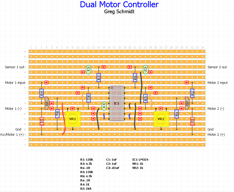
I am using DC motors and I am not using any mechanical tension control. The speed of a DC motor is proportional to its voltage. The torque of a DC motor is proportional to its current draw. The current draw of a DC motor can easily be determined via a low ohm sense resistor and an op amp. The current signal is input to your controller and can serve as the input to a PID controller implemented in software. To close the loop, the PID output to the motor is a PWM signal. Since the film is unwinding from a reel of known size, you can adjust the torque based on the calculated leverage of the unwinding film to the center of the reel. I believe this is a very simple and reliable way to maintain constant tension thereby avoiding mechanical dancers and such.

Greg, I’m curious to learn more but am afraid my knowledge is scant. Could you provide a drawing of the circuit you describe? I’d like to try it out. And how do you adjust the “calculated leverage” over time?

Hi Matt,
The current sensing is a fairly standard technique, I am using “low side current sensing”. I’ve included a link below. Sorry if I wasn’t very descriptive about the torque calculation. Basically you will choose a value for for your tension (or like I did, experiment/tweak until satisfied). It’s actually a force, so let’s call it F. From basic physics, you recall that torque is force times the lever arm (distance). In this case the “lever arm” is the distance from the center of the reel to the film (ie. the radius defined by the film currently on the reel). Since we’re “pulling” the tape off the reel, the force required to maintain a constant tension is proportional to the current radius of the “tape wheel”. When the reel is full, the DC motor requires a bit more torque to maintain tension, but as the reel empties, the “lever arm” (radius of film) slowly decreases and the DC motor torque can lessen (recall that motor torque directly relates to current draw). Every rotation, the radius reduces by the film thickness, until we reach the hub diameter and then we’re done. You could use a hall effect sensor on the reel to count rotations, but you don’t necessarily need to do that since you know the frame rate that you are digitizing at and with a little bit of basic math you could derive the current radius from that. It does mean that full reel diameter and hub diameter ideally are user entered parameters, but you might be fine with some nominal values. One more thing… I’m using salvaged cassette tape drive motors (my telecine is for 8mm). When external resistance is placed on a DC motor, it heats up and may lose some life. In my case these are 12v motors and I “derate” them by powering them at 5V. Plus the fact that I am using PWM to slow them down means that I am not stressing them. I have never noticed any warmth from them or had a problem, but I should mention that as a consideration. It’s rather late as I’m typing this, so if I have been unclear or left off some details, please let me know.

THanks for the link. I learned a lot. If I understand the concept correctly, you are measuring how many amps the motor is drawing. You are feeding that value into the microcontroller where you use it to determine the level of signal sent to the motor, via PID math.

In other words, you are targeting constant torque and you maintain it by measuring current and matching it proportionately with PWM.

Did I get that right?

I’ve also learned that I definitely did NOT want to order a three phase motor. I’ve ordered a couple more 12V and 24V motors, mostly around 150W to try out. With those results I should have a pretty good idea of what is working. In the running now are 3 general design patterns:

  1. Direct drive via pulley with the existing tension hub design
  2. Friction “slip” pulley with no tension hub
  3. @Greg’s current sense design.

@Greg would you mind sharing your code and schematics for that? It would significantly lessen my learning curve and speed up the testing :slight_smile:

1 Like

Yes, your recap is correct. The DC motor is in constant stall, which is generally not a good thing as it can cause the motor to overheat. But since I am using a lesser voltage than the motor rating, and monitoring current (which is a small draw for tensioning an 8mm reel), it isn’t a problem and the motor does not even get slightly warm.

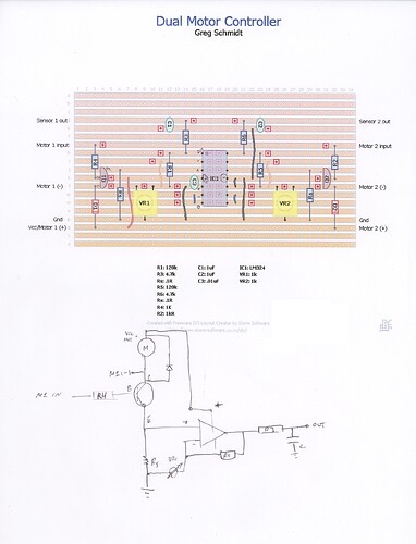
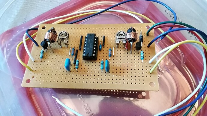
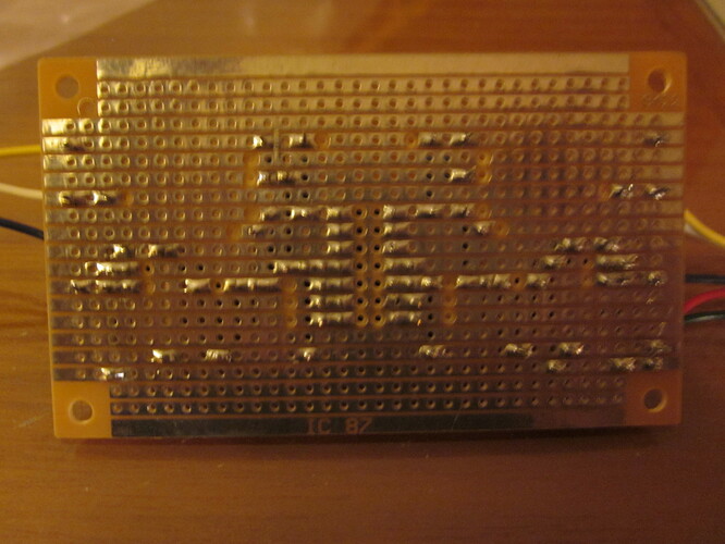
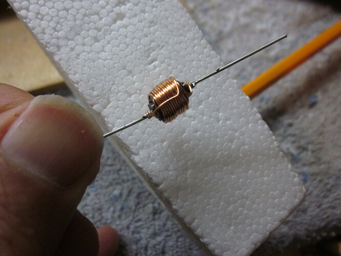
It was a few years ago, but I’ve attached what I’ve been able to dig up. Sorry for the hand drawn schematic. I made a 2 channel motor control board allowing tension control in both directions. I hand wound my sense resistors using wire salvaged from an old can opener and wound it around a fat resistor as a core (if you do that, make sure to fold the wire in half to create a doublestrand as that helps cancel out unwanted inductance). About the code, it is fairly simple and I did not implement any sort of “dynamic tensioning” as I described above. Although I have a working telecine, the project is on hold (I just don’t have the time right now) so I may or may not add that capability (it may be overkill).

CurrentSense.pdf (123.1 KB)

1 Like

This is great, thanks @Greg

1 Like

With the sprint coming to a close, here is my report: “Smaller is better.” I had taken the advice of someone early on when I picked the motor and never really questioned it. The suggestion of the GPN motors was a good one, and they have performed perfectly…which is probably why I never thought about changing it. But now that I’ve tried some other options, I can see now that we don’t need nearly that much power.

The design sprint, for me, was basically just ordering a bunch of motors and trying them out. I wanted to observe what kind of motors worked best, with different connections to the drive shaft, and to try out some alternative setups. Here is a summary of what I tried:

Permanent magnet motors
These are extremely powerful for their size. They can be found by searching for “scooter motors” and were a suggestion by a forums contributor (@milesjules) . At around $50-$60 they are a drop-in replacement for the GPN motors if you go with 150W or more. With a timing pulley, you can use smaller wattage motors too.
12/24V 150W High Speed CW/CCW Permanent Magnet DC Motor for DIY Generator(3000RPM(12V))

Walfront 12V/24V DC Motor 36W Large Torque Brushed Motor CW/CCW with Flange Wire(DC 12V 2000RPM)

YaeTek 36W Permanent Magnet DC Motor 2000-4000RPM High Speed Large Torque Motor 12V/24V (24v 2000rpm without flange)

HiGear 150W Watt 24V Volt DC Brush Electric Motor #25 Chain 11T Sprocket Unite ZY6812 f Razor Scooter DIY Kids Kart 150-GM150115 Works with 24V by Alfa Wheels (150W 11T Sprocket)

Yaegoo 150W 24V DC Electric Motor Brushed Motor Fit Electric Scooter Mini Bike, Go-kart, Bicycle or DIY Experiment from early research I did on how reel-to-reel tape machines work.

Of the above, none are a bad choice. But given the size and weight of some I ended up liking the YaeTek 36W motor. I ran it at 12V with the slip-drive system described below and got good results so I have ordered the 12V version to try with a less hacked-together test in the coming week.

Worm Gear drivetrain
Worm gears offer a torque boost and would allow the use of a much smaller motor, thereby reducing cost and shipping weight. While this did work, I found that it really wasn’t necessary given the success fo the pulley drive (see below). I did, however, like the way it worked and think it will make a good option for the capstan drive system.
Worm gear set from ServoCity
Motor tested with worm gear

Pulley System + Slip Drive
This proved to be the most valuable discovery of the sprint. Firstly, I found that using the timing belt-pulley system offered more torque than a direct drive (hooray for physics). This allows for a smaller motor.

Secondly, it seems an advantage to use a pulley system as it effectively (and literally) decouples the motor from the drive shaft and allows for different motors to be exchanged easily if the user chooses to do so.

The slip drive system came as an idea both from a forums contributer (@ednisley) and from research I did a couple of years ago on how reel-to-reel tape machines work. The video link shows it pretty well - it pulls when you need it to and slips when you don’t. The slip wheel was 3D printed and the surface area and material of the timing belt I had worked great with the plastic of the wheel to provide both grip and slip.

The advantage here is not only can we get away with a smaller motor, but we might also be able to get rid of the whole tension feedback loop/measurement system. NOW HOLD ON, I know what you’re thinking…“why would you want to get rid of measurement?!” Read on.

Conclusion and next steps
The sprint revealed that a) we don’t need big expensive motors to drive a full reel of 35mm film (our heaviest possible load), and that b) we might not need a feedback loop to measure tension.

In order to get a clearer picture of exactly what motor and what drive system will be best, more tests should be done and I’ve already ordered everything I need to do those tests. So stay tuned for more. As soon as I’ve decided on a setup for v2 Kinograph, I’ll post an announcement here and the results in the wiki.

More on removing the tension measurement feedback loop (aka the PID loop)
I haven’t decided anything yet, so don’t get too excited. I could use some help thinking this through so please offer your comments in this thread.

Review:
For those unfamiliar, the PID loop used right now is comprised of this hub and a PID algorithm that tries to keep the hub at a target angle at all times. This means that you should have steady tension at all times as the motor speeds up or slows down to maintain that angle at the hub.

Advantages of PID loops:
As I just mentioned, you get constant tension.
You can adjust the tension by changing a single value (with a knob, or in software)

Disadvantages of PID loops:
Complexity - we have a whole PCB dedicated to this with its own microcontroller.
PID tuning - because every potentiometer is not exactly the same and every machine will not be mechanically identical to the micrometer, the PID will need to be tuned for every system. While we can certainly make this easier through software or guides, it is still not an exact science and can lead to strange effects that are hard to troubleshoot like this one. To fix that you basically have to go into the code and fiddle with some numbers and keep trying until it works. Not ideal for a non-technical user.

What would life be like without a PID loop?

  • we’d probably just have one single PCB shield for the Arduino and all other connections would be simple cables or screw terminals. No more ethernet connections, multiple microcontrollers with their own codebase, etc.
  • Tension is still constant, and still adjustable. To adjust, we could implement a simple mechanical solution to increasing tension on the belt pulley (e.g. an idler wheel on an arm). Tighter belt = more tension in the film. Looser = less. Easy peasy.
  • less parts, simpler build

Given the above, I think it’s worth trying so I’m going to be focused on building a more complete test with both take-up and supply reels using slip drives and the capstan moving the film. I hope to report back soon!

Comments, thoughts, rants? Let’s hear it, folks!

1 Like

Matt,

I hope this isn’t a dumb question, but may I ask what a “GPN” motor is? (a google search did not appear to produce relevant results).

I may be biased towards PID as I’m about to hit my 40th year working in the field of industrial process control where PID has been, and still is the mainstay of electronic control. I’m not clear on why you needed to offload a single PID to another controller (our systems can run 100s of them in a single CPU, granted more powerful, but a single PID for tensioning doesn’t seem like a CPU hog to me). Also, the complexity of the PCB you mentioned, was it mainly I/O interfacing? To your point about tuning, couldn’t that be a “factory preset” for each machine? Once tuned properly, I doubt you’ll have to maintain it much in the future. You are using a pot which can wear so perhaps that is part of your concern, however with mechanical solutions you would also have to deal with changes due to wear over time as well I would think (so no free lunch either way, but at least with a PID you would have the option of “re-tuning” at that point). I should point out that there are auto tuning algorithms (if you need to take it that far, which I’m not certain is the case), but if you go that route, that adds complexity (to your point).

Also, “to PID or not” would seem to me to depend more on whether one is relying on mechanics or electronics (sensor/actuator) to perform the control function. I tend to favor electronic solutions, since mechanical parts wear out. However, to be fair, VCR’s have long used mechanical clutches for this sort of thing and I would say that VCR’s tend to break for reasons other than the clutch.

From a motor choice standpoint, my preference would be for longevity. I am using simple brushed DC motors, but I think a brushless DC motor would be ideal from the standpoint of wear, however they don’t operate at low speed so that brings you back to mechanical solutions such as belts and gearing for reduction. A stepper motor seems like a good solution to me as its brushless of course and can operate at low speeds. However, the question remains of how to sense the tension. I haven’t tried it, but the current monitoring solution I outlined above might work similarly for a stepper. Finally, maybe I don’t have a full appreciation for the film tension issue, but I wonder if all this is a bit overkill. Maybe a “good enough” solution is fine. I never quite understood why some telecine’s have “wheels upon wheels” of rollers and tensioning. Old movie projectors simply used springs as belts, and the slippage was “good enough”. I am using a film transport from a salvaged projector and the film is “captive” due to the two synchronized sprockets. That seems to nearly eliminate any need at all for precision film tensioning (for that matter, the film could simply be feeding from and to a pair of trash bins! :slight_smile: ). So if the main concern of film tension is to minimize film drift at the gate, then that seems to me to be the perfect solution! I hope I’m not rambling too much and feel free to correct/enlighten me on anything I have written that seems questionable to you as you have obviously immersed yourself into it whereas for me it has just been a part time hobby :slight_smile: . – Greg

Greg, thanks for the reply. I’m honestly at a fork in the road as to where I should head from here so your thoughts were helpful in getting the gears moving…pun intended. I’ve been going back and forth on how to move forward with the motor design.

PID - nothing wrong with it. Except we (the contractor and I) overcomplicated it as you pointed out. There is no need for such a complex PCB. We should have just made a connector back to the main shield. I would like to do that but do not know PCB CAD so will need to ask for help if we go that route.

When you’re not 100% sure how to pull something off, you tend to give more weight to other peoples’ opinions then sometimes you should. That’s what happened here. The contractor convinced me this was the way to go and now I am regretting it. Also, someone else told me that PIDs are notoriously fickle to tune and will be different for each machine no matter how precise they are made so that ultimately the end user will have to calibrate their own machine and that could be undesirable. I’m not sure if that part is true or not, regarding the difference machine to machine.

And so I had moved towards the slip design. It is very much like the spring belt you describe. There would be wear, yes, but I think it would be over a very long time before you’d have to change anything. And when you did, it would be very cheap and easy to change out. Anyone could do it.

So I’m at a crossroads…change the PCBs and go back to PID, or continue with slip drive while being uncertain of its validity as a design.

What parts seem overkill to you?

Oh, and as for motors I think you’re right. I’ll switch to using the permanent magnet motors I have and see how that goes. The savings of a cheap motor aren’t worth it if it has to be replaced more frequently.

I think the best way forward is to give the slip drive a decent shot but cap my research at a week. I’ll give it a full trial with capstan and all and post the results. Then we can assess together as a community as to the pros/cons.

Meanwhile, if anyone has Eagle CAD skills and would like to tackle the simplification of the tension hub PCBs, I’d love to hear from you. I’ll post a “Help Wanted” ad on the social media accounts this week and see if we get any bites.

Matt, Nothing here really seems as overkill to me (besides the separate controller/PCB you mentioned). I watched the videos of both solutions and my hunch is that either one of them will work just fine. The “slip” solution is an elegant mechanical way of achieving the goal and in some sense “simpler” since no external feedback loop is required. I do like the roller/pot solution too as it does allow you to fine tune its operation. It reminds me a bit of RC servos where the motor is internally connected to a pot and that works well in practice. I don’t know if wear of the pot will be a long term issue, probably not, but I would personally prefer an encoder rather than a pot, both for precision and life, but that’s just my preference.

As far as the PID tuning, yes PID’s can be difficult to tune, but for a simple tension application, I suspect that if you go that route, you’ll be able to tune it once, then forget about it.

I think all of the approaches discussed have their advantages and disadvantages, and in the end it may boil down to personal preference and taste. One man’s “simple” may be another man’s “complex” :slight_smile: .

You’re right about motor wear, it would probably be a milestone achievement to wear one out! :slight_smile:

– just some additional remarks: a slip drive would result in a constant torque applied to the reels. This in turn will change the tension the film is subjected to, depending whether the reel is full or nearly empty. The ratio of the tension variation will be identical to the maximum reel diameter divided by the minimum reel diameter. Depending on your goals, that might be tolerable or not.

In contrast, using an electronic feedback loop with a tension sensor (note that I am not using the term “PID” here :wink: ) will ensure that the film is subjected to a mostly constant tension (of course provided that the control mechanism is good enough).

Of course, the electronic feedback loop will also need to have a certain basic performance for keeping the tension within a certain range. However, the requirements for film tension are rather low - a slight difference between the tension requested and the actual tension does not matter, as long as the tension does not get so high that the film slips on the reels. Therefore, a “P” = proportional loop should be more than sufficient for that task. Such a proportional feedback loop is so simple that any microcontroller can update this many times per second. The “tuning” is simple as well: if the system oscillates, reduce the P-value (half it, for example).

Last note: an additional advantage of having tension sensors in the film path is safety - if the film breaks, the tension sensors will notice this and the whole unit can be shut down immediately. In the case of a slip drive, the constant torque such a drive is applying to the reels will actually result in a speed-up of the reels following a film breakage, until friction forces will limit this runaway somewhat. Actually something any projectionist will have experienced once in a while, I guess. Probably not something you want to experience with unique archival material…

1 Like

@cpixip Yes! Some science to guide us! Thanks for your expertise. This really helps push things back towards the PID side. I’ve come up with a simple test for the slip system and want to follow-through with it because I’m learning something new by doing it and that’s always a fun reason in my book. I am waiting on a new belt which should arrive Tuesday.

For film breaking with the slip motor I was just planning on having a simple sensor in the film path.

@greg GPN referred to the model of the motor.