Your XY adjustment platform looks great! Would you be willing to post parts and design files for that? Forgive me if you already have.
Hello Matthew, at theis point in time, the design is barely usable, so I would rather opt to not share it rightaway. But, at the moment, I can describe the design of the xyz-stage and the current status of it. That might be of interest.
There are several reasons why the design is not up to the task: first, the 3D-printed structure is just not as rigid as, for example, a professional xyz-stage (which start at slightly above 150€ on the usual shopping channels). Secondly, the plastic “bearings” I miss-used in the construction of the sliders have a slighly too large gap between them and the axis they are sliding on. Lastly, the 3d-printing of that stuff needs quite some tuning of the 3D-print process in order to obtain good results.
Anyway, here’s a sketch of the basic principle: the xyz-stage pictured in the comment above is actually a xyz-stage composed of three identical slider units, connected with three different connectors so that all three axis can be independently adjusted (that point is one of the points which does not work with the current version).
A single slider unit looks like this:
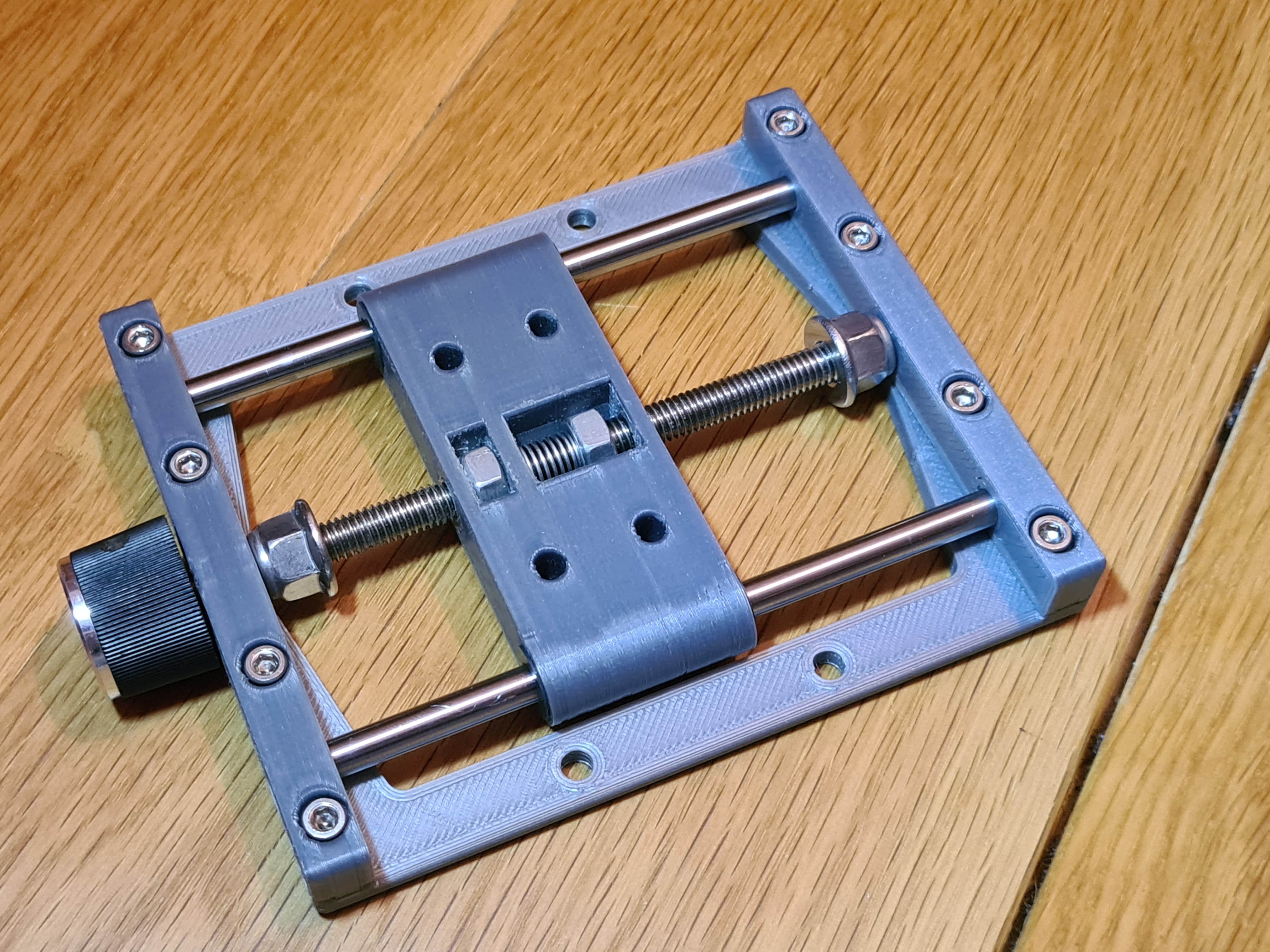
There is a base which supports two holding blocks for two Ø 5 mm steel axis and a standard M6 threaded rod in the center. This threaded rod is fixated between the holding blocks with two stop nuts. The fixation via the stop nuts is a little bit difficult to achieve - too loose and your slider does move on its own, to tightened, and the thread is hard to turn.
The slider itself has two M6 nuts. The left one in the image above is fixed, the right one is able to move. One the left side of this nut, there is a spring (hard to spot probably) which keeps a certain tension between the fixed and the moveable nut. That is a simple way to reduce backlash.
I misused some plastic bearings I had for realizing the sliding mechanism. They can be seen in this picture in better detail (it’s an IGUS part, the dark brown circular thing):
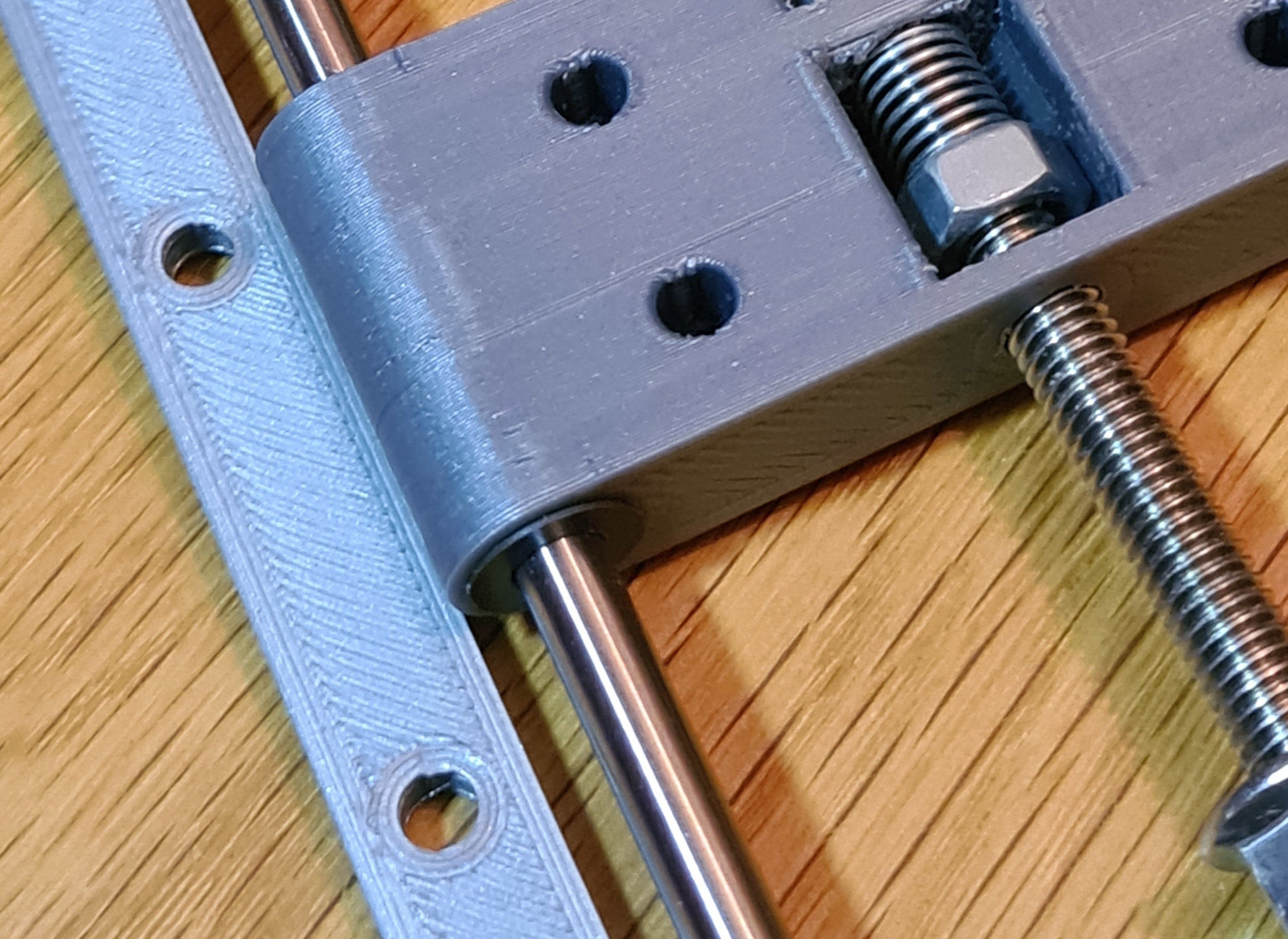
As it turned out, the tolerances between the steel axis, the plastic bearing and the 3D-printed part are just a little too large to fix the movement of the slider reliably in only one axis (which is the intention of the whole construction). The slider can also tilt a tiny little bit around an axis perpendicular to the main axis. So far from all stages I printed, only one of came out with negligible tilt, just by chance probably. There’s certainly room for optimization here…
The units are designed on purpose to be very slim, because three of them are put together into a xyz-stage with special connectors. You can see them (the colored pieces) in the following rendering of the stage
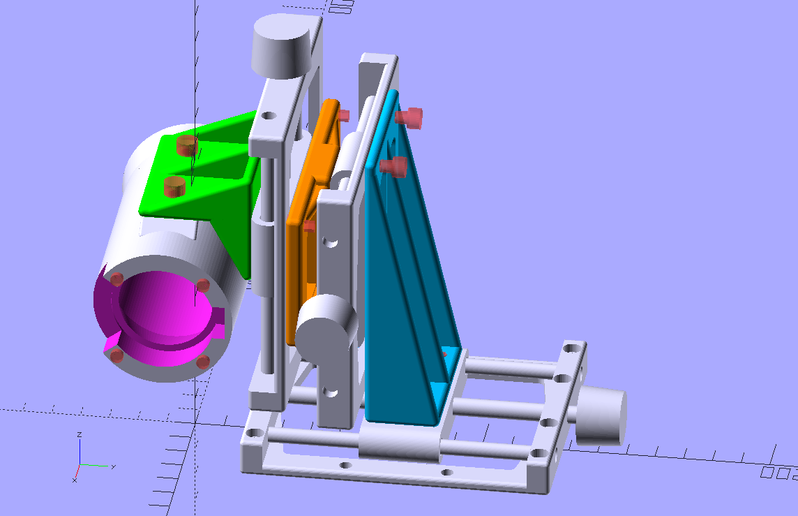
During the initial tests I found out that I would have actually needed an additional, fourth axis - namely the rotation of the camera around the optical center of the frame. But I found no easy way to implement that. So instead, I measured the necessary correction angle and reprinted the green connector in the above image with an angle slightly different from the initial 90°. That worked.
Anyway. At the moment, this design is better than what I had before, but there are certain points which need improvement:
- I printed this in PLA. Compared to steel or aluminium, this plastic is quite flexible. If you touch the camera or one of the dials of the xyz-axis, the image jitters. It is not impossible, but it is hard to focus with such behaviour.
- An additional drawback of that missing stiffness of the setup: even the slightest vibration shows up in the scanned images. In my current setting, a back of the envelope calculation shows me that a single pixel corresponds to about only 2.5 microns on the film. That is a tiny distance! Any movement will show up in the scan. So currently, the whole scanner has to be placed on a platform which is sure not to move. I simply use my lab floor for this, but even then, very heavy footsteps can be “recorded” by the scanner…
- The tilt of the slider which I mentioned above certainly needs to be reduced. One way to do this might be to design a better fit between plastic part and steel axis. I need to look into this. Another option would be to increase the span the slider is using. Each slider is currently about 28 mm in length which gives me a rather large sliding range of approximately 50 mm. I do not need such a large sliding range on any of the axis. Increasing the span of the slider will reduce both the sliding range as well as any tilt I want to avoid.
- Another thing I discovered during testing: the M6 thread I am using has a pitch of 1 mm per revolution. For focus setting, actually a slightly larger pitch would better match my taste. But I think I will not bother with this.
There might also be other points in this setup I have not yet discovered.
Well, what might be of interest to the community is the design of the camera body:
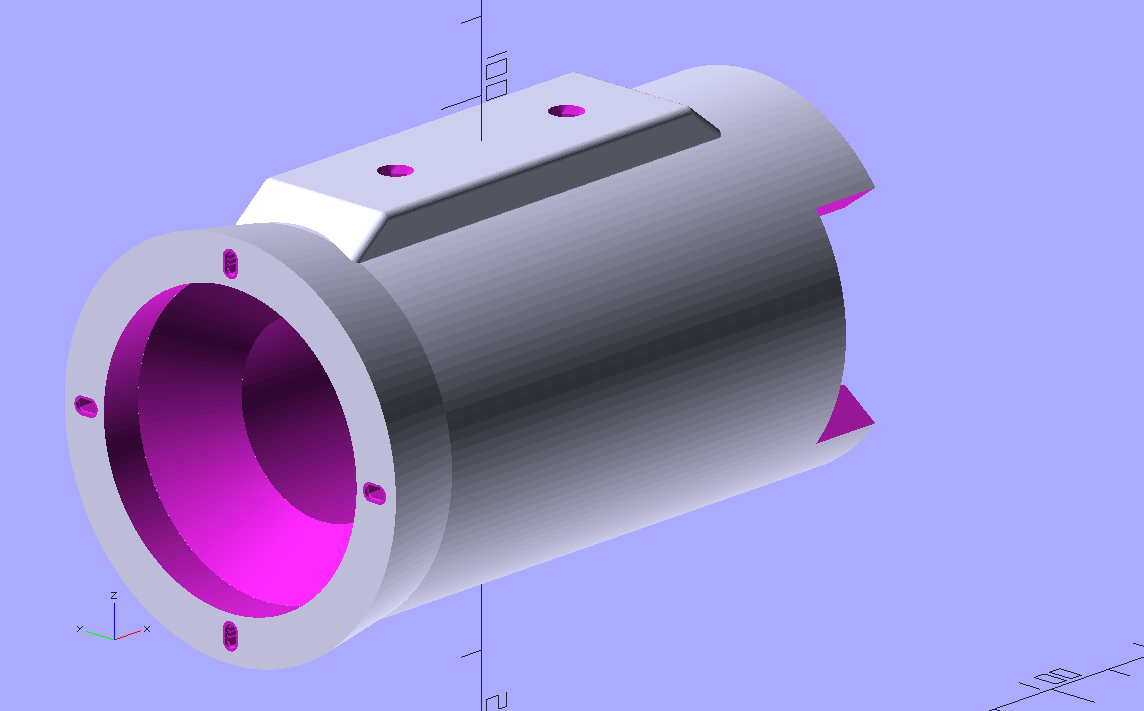
The distance between camera and lens is fixed at 91.5 mm; as explained above, this gives you approximately a 1:1 optical imaging with the Schneider Componon-S 50mm, with some slight overscan of a single Super-8 frame.
Since my printer is unable to print the M39 thread of the lens, I opted to reuse some photographic mounting plate I had. Since the screws of this plate are very tiny, I created not holes but tiny slits for them (visible in the above 3D-rendering).
Note also the circular cone just after the mounting plate - this gets rid of stray light from the light pipe of this lens.
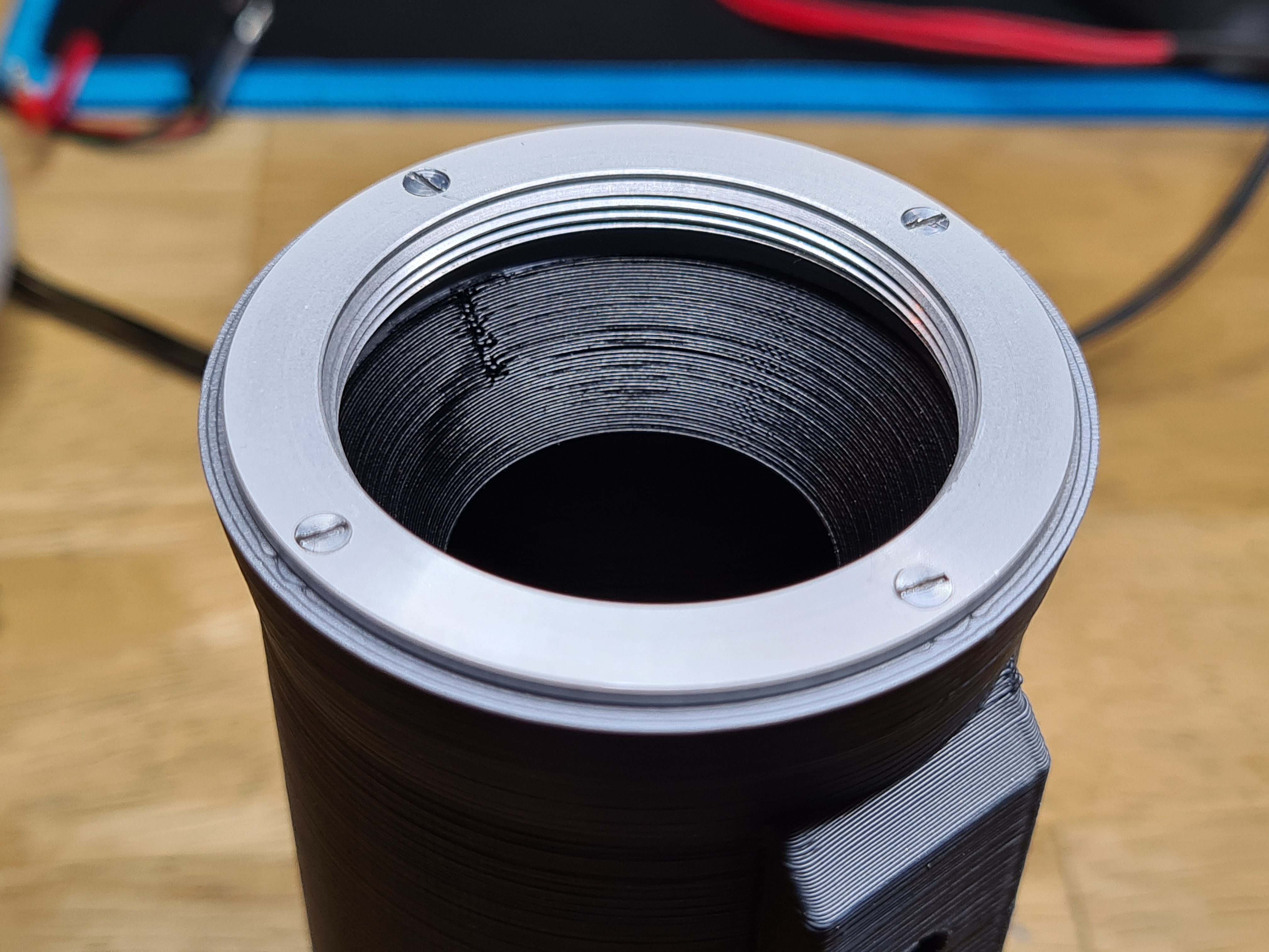
To further reduce stray light, I covered the inner section of the camera body with matte black paint.
Finally, here’s an image of the “business side” of the camera body, holding the Raspberry Pi HQ camera:
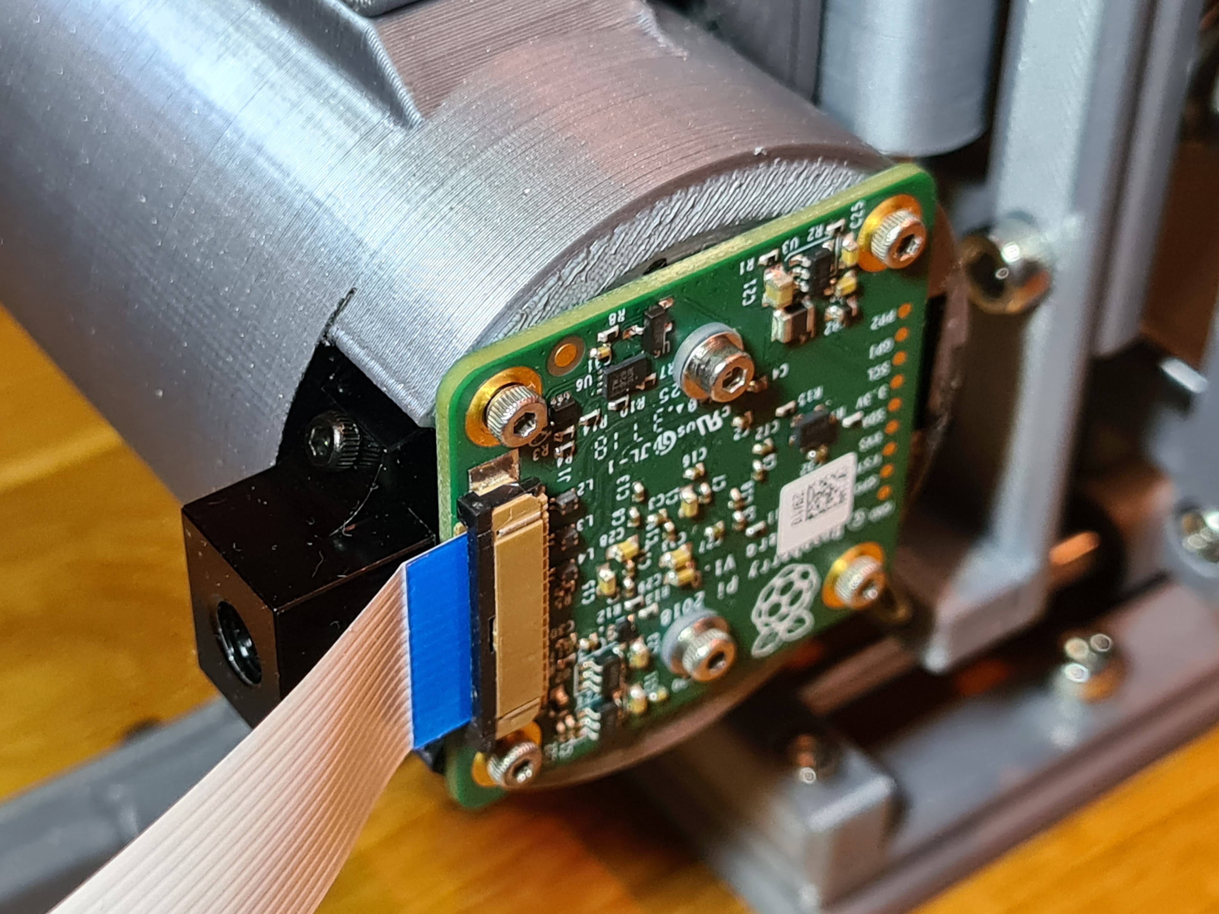
And here’s a link to the .stl-file of that camera body.
2 Likes
This is fantastic, thank you for the documentation and explanation. This will give anyone wanting to make their own a lot to go off of. When I get to that stage I’ll definitely be using it as a reference!