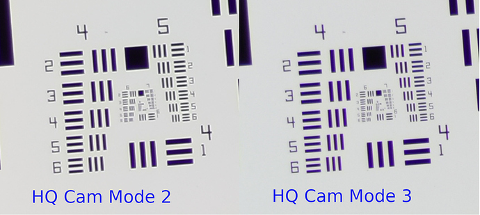
Yes, indeed. In full resolution mode, the free-running transfer speed is slightly below 10 fps, but in the binned mode 2 the transfer speed reaches 30 fps (which is the maximum possible as I am working with an exposure time of 1/32 sec). Of course you are loosing resolution in the 2x2 binned mode, but 2016 x 1512 px is more than enough for my purposes. As an added advantage, the binning reduces the sensor’s noise level by a factor of two.
Well, the pipeline of the HQ cam uses certainly a different processing scheme. Have a look at my tests with the HQ cam with different quality settings. Clearly, the quality parameter is treated differently in the HQ camera compared to the v1/v2 sensors. There was also some discussion about that on the Raspberry Pi forums, but I cannot locate that post any more.
The main advantage of the HQ camera is that it features a 12 bit DAC, as compared to the 10 bit DACs found on the v1/v2 cameras. Also, if you use the 2x2 binning mode, you in effect work with a four-times larger pixel size than specified in the data sheet for this sensor. This tends to reduces image noise.
Given, with that binning mode, the effective resolution of the HQ cam drops down to 2028 x 1520 px, as compared to 2592 × 1944 px with the v1 camera, for example. But as you noted already, you get a much better camera signal, especially in dark image areas. That is my main concern, not resolution, as my movie format for sharing these old digitized Super-8 movies is usually only 960 x 720 px anyway.
Let me elaborate a little bit on the topic of lens-shading. Normally, you should do lens shading compensation with the raw sensor signal. Basically, because the lens shading tables are just local multiplier tables for the 4 color channels coming straight out of the sensor chip. The purpose is mainly for compensating vignetting effects by appropriately scaling the raw camera signal before it enters further processing steps in the image pipeline.
If you do the lens shading compensation on the PC-side, you need to use normally the raw image. This might be delivered as an appendix to the normal .jpg, if you instruct the Pi to do so. However, if you do lens-shading calculation on a jpg-image, that will only partially work - namely in the intensity range where the jpg-pipeline is more or less linear. It will certainly not result in a good compensation in dark and bright image areas, where the jpg-pipeline is highly non-linear.
Also, while lens shading can compensate for vignetting effects, it cannot compensate for cross-talk between color channels. That is simply not possible because of the mathematical operations involved. For compensating cross-talk, you would need a (4x4)-matrix operation for de-mixing the different color channels, but within the lens shading context, you have only a single multiplier available for each color channel.
Now it is important to note that when you pair a long focal length lens with the micro-lens array of a v1/v2-sensor tuned to a lens of say 4mm focal length, crosstalk is introduced between the color channels.
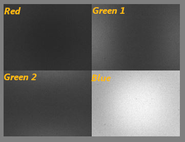
Here’s an old example showing that effect from a v1-camera experiment, where the camera looked at a pure blue background:
What you see is the spill of the blue color component into the other three color channels. Ideally, the blue channel should be a homogenous gray tone (it’s not because of vignetting and dirt on the sensor), and the other color channels should be just pure black. This is obviously not the case. Note the asymmetry between green channel 1 (spill left and right) and green channel 2 here (spill top and bottom). That is caused by the different geometric positions of these channels with respect to the blue channel. In any case, the important point is: you get a color spill if you match a v1/v2 camera with a long focal length and you cannot compensate this color spill within the context of a lens shading algorithm.
In the end, the color spill results in desaturation effects and slight color shifts for certain colors, noticable towards the edge of the image frame. This effect is much less severe in the v1- than in the v2-camera, but it is measurable and noticable.
Given, you can tune the lens shading at the start of a reel so that the empty gate appears pure white, and that setting will give satisfactory results, especially with the v1-camera. But there will be tiny color shifts towards the edges of the frame for any color which is not white/gray. However, since you are using only the center part of the camera image, chances are that this issue is not noticable.
Finally, I do not think that I can do much more to speed up processing with my hardware. Actually, line number 10 of my python script is already
import multiprocessing as mp
and I am employing some other processing tricks as well for speedup. That is the reason why my python script is only one third slower than the compiled opencv version. When I started with this code, processing times of the python script were on the order of 7000 msecs or slower per frame.
Anyway, it would be interesting for me to get some timing information about the standard exposure fusion algorithm on other hardware. The processing times reported above have been obtained with the following code segment:
import cv2
import time
time_msec = lambda: int(round(time.time() * 1000))

merge_mertens = cv2.createMergeMertens()

tic = time_msec()
result = merge_mertens.process(imgStack)
toc = time_msec()
Here, the imageStack is just the python list of the 3 or 5 source images for the algorithm. It would be great to see how fast that algorithm is performing on other hardware.
