Projector based system

I am probably guilty of hijacking other threads a lot, and will be asking plenty of questions, so I figured I’d start a thread to discuss the system I’m building. I’ve taken a shortcut by starting with a Eumig 610D projector to give me the following out of the box:

  • motor, with constant (ish) speed of 3fps
  • film transport system
  • gate - though this had to be removed, filed and put back to get the full frame displayed

I actually started this project a decade ago, but life has a habit of taking over. At the time I was tinkering with a HV20 and condenser lens imaging solution, but hated that and the project stalled in 2011 just after I decided to go for a machine vision camera.

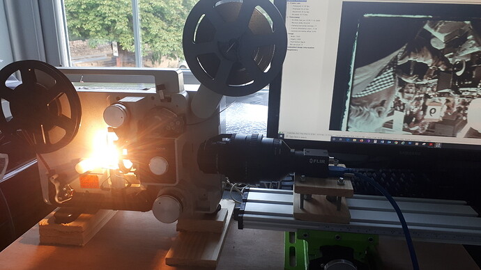
The shutter blades have been removed, gate opened up as mentioned, and I replaced the bulb with a 20w halogen on a dodgy but effective aluminium bracket. It uses a 50mm opal diffuser, that is an excellent interference fit and secured with some industry standard blu-tac. I had tried a microswitch on the tensioner, but ditched that eventually for a hall effect sensor (inspired by http://www.cine2digits.co.uk/).

Getting the system working again this year has been a key objective, and I managed to get a brand new Flir BFLY-U3-23S6C-C camera from Gauge Film (UK lab) at a good price as new old stock. The setup as it stands is:

Schneider Componon-S 50mm enlarger lens, reverse mounted > 43-52mm step up ring > 52mm reverse adapter > 52mm to 42mm helicoid adapter (25-55mm) > 11mm extension tube (42mm thread), then a Kood M42 to C mount adapter.

This now gives a really good range of enlargement, and with the moving helicoid adapter, I can choose whether to overscan.

The camera is triggered by the hall effect sensor circuit shown above, prototyped on the breadboard. I’ve had quite a bit of fun playing with that, as the Flir camera specs weren’t particularly clear on what the trigger circuit needed to do.

By trial and error I’ve realised it needs an input of around 3.8v or higher. The hall effect sensor (SS443A) receives 5v from a USB mouse (circuit board seen in the photo) as it was the first 5v source I had to hand. I might retain this as it’s quite nice to be able to quickly plug in a USB cable to get things powered up. To get the right voltage to the machine vision camera, there’s a 330 ohm pullup resistor there in use between two of the sensor pins.

The USB cable of the camera goes into a PCIe card (bought from Flir). It’s more or less stable enough for me to start trying to transfer some film with it, and the first results aren’t looking too bad:

agtest

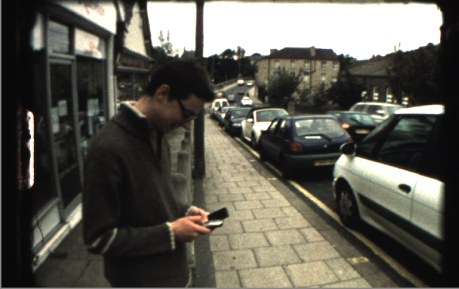
The above frame is Kodachrome 40, taken with a Canon 814XL-S.

First impressions of the system are as follows:

  • The 20w halogen bulb is not bright enough. With an aperture of f/8 on the Schneider lens (thanks @cpixip, I think it was you who recommended f/5.6-8) which is the brightest I’m happy with the DOF, the effective gain or shutter speed of the machine vision camera isn’t right.

I have to either crank the gain up (creating digital noise), or increase the shutter speed to the point where the risk of image blur from the frame moving is quite high. I can probably mitigate this to an extent by playing with delay on the hall sensor, but that’s not ideal.

  • The Flycap2 software supplied with the camera does a very good job of automating capture. There’s not a great visibility on how it’s making detirminations on white balance and exposure setting (it must be including the light and dark areas around the film, which can’t help accuracy?), but it is pretty much plug and play.

  • Sadly the exposure bracketing we discussed in HDR / Exposure Bracketing - #8 by cpixip isn’t natively easy with the Flycap software. The HDR feature in there is a demo mode, which fixes the capture to 4 frames, and doesn’t natively work with a 1 trigger per frame setup. I would have to find a way of making the camera interpret each trigger as 4 triggers, probably mechanically, if I wanted to avoid writing software. So it looks like I’m probably going to have to write a custom application (anyone got any books on C++? :slight_smile: )

  • I’ve never worked with uncompressed AVI files this big, and it pushes HDDs to the limit. I was going to use them as part of the workflow, with SSDs as the main capture drive, but now I think they’ll just be relegated to storing the fully scanned and processed movies.

My long term goal is to migrate this system to a Kinograph type machine, with much more flexibility, but for now things seem to be going well.

4 Likes

Next steps - join in with the excellent lighting research you guys are doing.

Because I need to retain the projector for now, I’m very interested in the L shaped diffusion prototypes. Once I’ve got some COBs and a heatsink (probably a used PC CPU heatsink/fan), I’m seriously considering trying out using a 40 or 50mm solvent weld pipe bend. I have a lot of them left over from doing the bathroom last year, they are white plastic and the right shape! :smile:

2 Likes

Nice job!
You can also try Flir’s Python API to get more than one frame per shot.
We use the API instead of flycap to get the frames and convert the RAW files from the camera with OpenCV.
It works very well

Glad to see you are capturing frames, that means you are learning real stuff! (Unlike my situation)
1 frame trigger to 4 camera triggers?
This is a natural for using an Arduino. Yes, you would have to code a little bit, but the Processing/Wiring language is way simpler that C++. Trust me on this cause I have forgotten all the C++ I knew!
Really like your re-purposing of the mouse circuit board. I have been pitching out excess corded mice, but now there is a reason to save a few.

Hi @Jofkof, do you have a link for the Flir Python API? I did a quick search for it, but may not be looking for the right thing. I’ve got a Chameleon camera that I’m trying to talk to.
Thank you!

HI @junker, try FlyCapture SDK | Teledyne FLIR for windows or linux

Thanks all. I guess Python may be a better bet?

I’m really only familiar with common web languages like HTML, CSS, PHP and Javascript, but there’s an added bonus to Python in that I’ll probably get more from my Raspberry PIs from learning it.

Any recommendations for making the transition from web to software, and building a desktop app on Windows for the first time?

As an aside I’ve got an Arduino already, but it was preprogrammed and part of a MIDI Arpeggiator kit I bought to use with my old 80s Roland Juno synthesizer. I really like the idea of them, they seem much better for controlling things in the physical realm than the Raspberry Pi. Just different tools, both equally brilliant.

Glad to hear this has worked for you @Jofkof. Do you have code you are willing to share?

@bainzy Python is a great option and I would recommend that. I hope to make any/all programming in the new Kinograph v2 in python if possible, including the Arduino code via CircuitPython.

Yes, sure.
Our scripts are specific for our scan system.
There are several code examples whitin the sdk
But, what kind of script are you looking for?

Ah, I thought they might be of use to someone else here but if it’s all specific to a system that no one else has access to I guess it’s not that useful. I am always trying to encourage people to share as much as possible on the forums. Thanks for your contributions!

You can come to Montevideo to know our system whenever you want! In fact we have shared our experience with other institutions that have the same basic equipment. It is a matter of hardware and its integration. Our scanner is based on a Rank Y-Front equipment controlled with an Arduino board and a Flir BlackFly camera to scan 16 and 35 mm films. We use C (Arduino), python, OpenCv and DaVinci. Also a lot of ffmpeg. Especially for post-producing movies at less than 24 fps. Perhaps these developments made by our colleagues can be of interest to the forum Ignacio Hounie / alineado-film · GitLab or this other https://iie.fing.edu.uy/~ihounie/ timag_pag / index.html
This is the code that controls the progress of the film. It is Arduino code:
//define pin name
#define dir_1 7
// pwm
#define pwm_1 4
#define pin_disparo 10

#define switch_1 13
#define luz 8
int sacar = false;
float pwm_value=0;
int disparo = 0;
char option = ‘1’;
void setup()

{
//declare pins as INPUT/OUTPUT

pinMode(pwm_1,OUTPUT);
pinMode(dir_1,OUTPUT);
pinMode(pin_disparo,OUTPUT);

pinMode(switch_1, INPUT);
pinMode(luz,OUTPUT);
digitalWrite(dir_1,0); //controla sentido delmotor 0 adelante 1 patras
Serial.begin(9600); //Serial monitor

}

void loop(){

   int sensorValue = digitalRead(2);
   
   if (Serial.available()>0){ 
                  char option = Serial.read();
                   if (option == '0'){
                    digitalWrite(luz,HIGH); //prende
                      sacar = false;
                      pwm_value = 0;
                      analogWrite(pwm_1,(pwm_value));
                                     }
                    if (option == '1'){
                      sacar = true;
                      pwm_value = 24;
                      digitalWrite(dir_1,0);
                      analogWrite(pwm_1,(pwm_value));
                                     }
              
    if (option == '2'){
                      sacar = true;
                      pwm_value = pwm_value+2;
                      analogWrite(pwm_1,(pwm_value));
                                     }
              
              if (option == '3'){
                      sacar = true;
                      pwm_value = pwm_value-2;
                      analogWrite(pwm_1,(pwm_value));
                                     }
       if (option == '4'){
                      sacar = false;
                      pwm_value = 48;
                      digitalWrite(dir_1,1);
                      analogWrite(pwm_1,(pwm_value));
                                     }
              }
     while (sacar) {
              sensorValue = digitalRead(2);
              
              if (Serial.available()>0){ 
                  char option = Serial.read();
              
                   if (option == '0'){
                    digitalWrite(luz,LOW); //prende
                      sacar = false;
                      pwm_value = 0;
                      analogWrite(pwm_1,(pwm_value));
                                     }
                   
                    if (option == '1'){
                      sacar = true;
                      pwm_value = 20;
                      analogWrite(pwm_1,(pwm_value));
                                     }
              }
             
                  sensorValue = digitalRead(2);
                            analogWrite(pwm_1,(pwm_value));
                            sensorValue = digitalRead(2);
                            //Serial.print ("While ");
                            //Serial.print (sensorValue);
                                       
                            
        if ( sensorValue==HIGH and disparo == 1){
              analogWrite(pwm_1,(0)); // Para el motor
              delay(600);
              digitalWrite(luz,LOW); //prende
              delay(350);
              digitalWrite(pin_disparo,LOW); //dispara
              delay(9);
              digitalWrite(pin_disparo,HIGH); //disparo
              delay(300);
              digitalWrite(luz,HIGH); //apaga luz
              disparo = 0;
        } 

         if ( sensorValue==HIGH){
          analogWrite(pwm_1,(pwm_value)); // re arranca

         }
              
        if (sensorValue == LOW){ 
             disparo = 1;
             }

           }
       }

Hopefully something so specific will serve someone.

A small contribution on account of more!

1 Like