[v2 dev] Milestone 3 - Lighting

@cpixip I am doing some improvements to light source for the second round of a frame-by-frame 8mm/super 8mm DIY.

First and foremost, I have no clue on what are the particulars for best light source. I did some experimenting using a circular polarizer placing it in various locations and comparing, and had some interesting (and some puzzling) results. The setup is light source - film - inverted Nikor 50mm F2.8 - below - DSLR Nikon D3200.
When the polarize was set between the light source and the film, there seem to be an slight improvement in details (dust/scratches) and the grain seems less prominent. In other locations, the grain seemed to improve at the expense of less details. To say that the changes were subtle is an understatement… but given my clueless approach, would like to ask if you have any experience before I chase the rabit down this rabit hole.
Thank you

Interesting - were you by any chance using pairs of polarizers? Or was it just the one circular polarizer placed between the light source and the film?

The Callier Effect has more to do with collimation but it’s possible a similar effect could be observed with polarized light… you could also have a well-collimated light source and I just don’t know about it :slight_smile:

Only a single circular polarizer. Do not have a linear polarizer, although thinking about getting a linear film to do more testing.
Definitely do not have a well collimated source.

If you introduce polarizers into your imaging pathway, be aware that there iexists the so-called photoelastic effect. Many translucent plastics show stress birefringence and you can make colorful images of the stress distribution in a sheet of plastic with polarizers.

With respect to “optimal” LEDs: I actually tried to approach that issue somewhat scientifically, and calculated the transfer functions of my intended “LED->film->camera” setup. To do so, you need the emission spectra of the LEDs, the transmission spectra of the film stock you are working with, and finally the spectral response curve of camera chip you are using. Needless to say, it is quite difficult to get hold of such data.

I did the calculations anyway and came up with an “optimized” setup. However, as it turned out, this setup was far from optimal. For example, the RED LED was way too far emitting in the infrared and the scanner picked up and amplified uneven exposure of film stock which I did not see in a normal projection of the same movie.

So in the end, I simply tried out different sets of LEDs until I got something workable for me (details are noted above somewhere). It seems to depends only slightly on the film stock, much more on the camera and how its internal color calculations work. Also of course on the design of the illumination system. I opted (as detailed above) for a very diffuse one - it reduces the amount of scratches you are going to pick up. But, as @johnarthurkelly already noted, it reduces image contrast…

It’d be very interesting to see the work you’ve done calculating the transfer functions for your setup @cpixip!

Would you mind sharing your camera and lens setup as well? I believe this information could help shed some light on the concept of the imaging chain/system for other group members.

@PM490 @cpixip I actually think both of you would find this paper interesting:

Optical Detection of Dust and Scratches on Photographic Film

@johnarthurkelly: well, that was long ago (2018) and did not result in anything usable. What I did was basically the following: I searched the internet for characteristic curves of movie stock and the camera I was using at this point in time (a Raspberry Pi v1 camera). I then digitized these curves from 400 nm to 700 nm and combined them. This allowed me for a specific LED to calculate the response as well as the cross-talk to other channels. Here’s an example:

Unbenannt

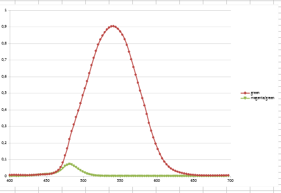
The red graph is the expected main response, the green line is a slight cross-talk. The idea was to maximize the difference in the color channels to capture most of the colors. However, the set of LEDs that I ended up with did not perform well. Specifically, as far as I can remember, the following issues arouse:

  1. The LEDs choosen had quite different efficiences. I had only access to relative intensity graphs, and there was no easy way for me to correct that.
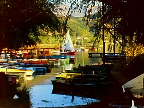
  2. The Red LED turned out to be too much on the IR-edge, actually enhancing some fixed dark red pattern which might have been caused by the uneven coverage of the daylight filter of the Super-8 camera. This was only visible in a test movie I bought via eBay and in my scans of that movie, not during normal projection of that movie. However, it prompted me to abandon that approach. I do not have a good example available any longer, but here
    vlcsnap-2020-03-02-20h19m59s476
    you can notice a dark read glow in the lower right corner of the frame, in the shadows. It is a pattern fixed to the film frame and has a form similar to a too small filter.
  3. I discovered that the cross-talk of the Raspberry Pi camera chip v1, if combined with my Schneider 50mm lens is much more noticable than the cross-talk I was trying to minimize with my transfer calculations anyway…

So in the end, I simply bought a bunch of LEDs and swapped them around until I got something which worked… :slightly_smiling_face:

Ok. Now for the camera/lens setup. Initially, I started with a Raspberry Pi v1 camera. I was aware that there is a slight color shift introduced by the mismatch of the microlens array of the sensor and the lens I was going to use: a Schneider Componon-S 50 mm.

But I developed a technique to compensate that, basically taking several exposures, calculating an HDR image from that and then compensating in HDR-space. However, that was a slow process.

When the v2 version of the Raspberry Pi camera came out, I immediately tried to switch to that camera - only to find out that the mismatch between microlens array and a long focal length lens (compared to the standard lenses these cheap sensor are designed for) is even worse. However, at that point in time the Raspberry camera software introduced the possibility of a lens shading table. I implemented that in my software, and I got resonable results with the v1 camera sensor, using a modified picamera library. It was much faster than my HDR-space based compensation.

With the newer v2 camera sensor however, the results kept being disappointing. I could compensate the color shifts, but the cross-talk resulted in a noticable loss of saturation towards the edges of the image frame. So I reverted to the v1 sensor chip.

I finally abandoned the Raspberry Pi setup alltogether because I discovered that certain colors were not really reproduced good enough - especially brown tones still showed a tendency to be saturated in the center of the frame, but desaturated on the edges of the frame.

My current setup consists now of a See3CAM_CU135 camera, mounted onto a Novoflex bellows with a custom 3D printed attachment. On the other side, the Schneider lens is mounted, fixed at an f-stop of 5.6. Supposably, this is the f-stop with the sharpest image. This setup is currently on a freely movable platform which is moved as a single unit to get the frame into sharp focus. There is certainly room for improvement here.

Here’s an image for illustration

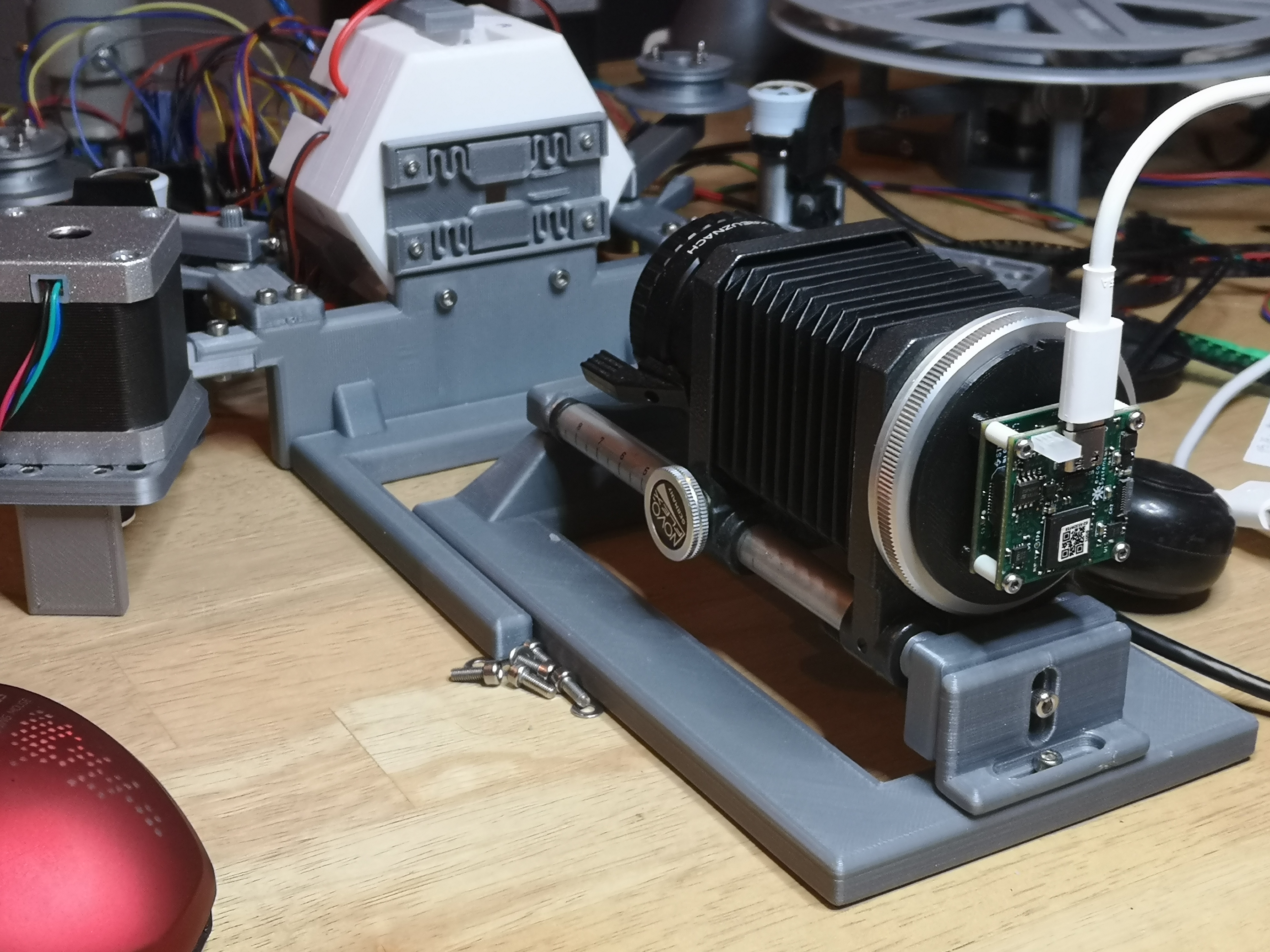
In the background, you can see the film gate attached to an integrating sphere, which I described in detail above. A note about the See3CAM_CU135 camera: if you consider this camera, it is best to use a Linux-based host computer and v4l2. At least I was not able to interface the camera well enough with Win7 or Win10 systems to use it. Example captures can be seen in my post found in this thread: HDR / Exposure Bracketing

And finally: thanks @johnarthurkelly for the link to the paper. Indeed interesting!

3 Likes

Thanks @cpixip for the setup, and @johnarthurkelly for the link to the paper. Interesting foundation for playing some more with the polarizer setup. Thank you

1 Like

@cpixip Can you explain your gate design? I see the two tabs for horizontal alignment on springs, but I also see two ramps on the right side of the film path. Looks very interesting, but I’m unclear on each part’s function.
Thanks!

@junker - Ok, here’s the story of this gate design.

My goal was to create a mostly 3D-printed design of a Super-8 film scanner. The illumination approach I am using is an integrating sphere (see above). This light source requires for its intended function a film gate very close to the exit pupil of the sphere. If that is the case, small scratches are reduced by the mostly diffuse illumination.

My initial attempts with film gates scrapped from old Super-8 projectors turned out way to bulky, so I decided to take the challenge and design a very flat 3D-printed gate. The specific challenge was here that my 3D-printer, an ANET A8, can print reliably only with about 0.2 mm in the z-axis. That is larger than the average thickness of Super-8 film stock.

The core design is a block with a V-shaped groove, which guides the film only on the edges:

The film channel of the V-groove has the minimum width possible with my printer, of about 0.2 mm. Two identical blocks together with a mounting box compromise the film path:

The two V-groove holding the film in place are attached via some 3D-printed springs to the enclosure; I borrowed that idea from the designs of xyz-flexure stages which are routinely used for very precise movements. These springs are very stiff in the direction of the camera, so the film always stays in focus, but move easily if the film width or film thickness changes.

Of course, it took several iterations before the spring design action worked as intended. Here are some examples of the iterations this design went through:

If I do a next generation, I will fix the lower V-groove to the enclosure. Only the upper V-groove will be able to move via springs. This will minimize a slight wobble which is noticable in the current design if a film cut is encountered. Super-8 film was spliced together with adhesive pads, and they wrap around on the side of the perforation, increasing the width of the film material at that side only. With the current design, both V-groove adapt and move. Ideally, only the upper V-groove should react.

Finally, the two ramps you are seeing in the final design are just guides which ensure that the film, when inserted manually into the gate, is directly aiming at the tiny V-grooves of the film gate. Without these ramps, it is rather difficult to correctly insert the film into the gate. Here are two enlarged view of these ramps and the V-grooves:

If you look closely, the ramps do not reach the level of the V-groove, ensuring that when the scanner is in operation, the ramps do never touch the film. They are just there to help the manual insertion of the film.

In closing, here’s a full view of the gate.

I hope the images and remarks above clarified the design; it the end, it’s a rather simple piece of plastic, with only three 3D-printed parts.

3 Likes

Brilliant. Thanks for the detailed write up and clear images.

Having first thought of trying a Wet Gate to reduce scratches, I’ve also started pursuing an integrating sphere design.

Thanks for being so willing to share so much of your knowledge.

Agreed! Thank @cpixip. This is fantastic. Are the 3D-printable files available somewhere online?

Awesome work on the gate design @cpixip. I’m surprised at the depths you’ve gone to with every aspect of the system, whether that be physics and experimentation for the parts, or programming for the software.

With S8 cameras there always seems to be talk about lack of pin registration compared to decent 16mm cameras, and then videos like this (Logmar S8 Camera & Kodak Vision 3 50D Super 8 - 2K Scan on Vimeo) crop up that suggest when a camera does have it, the difference in overall impression from S8 footage is notable. I guess the tautness of the springs in the direction of the film edges is hopefully doing the same thing as pin registration, but without needing to touch the perforations at all.

Whilst an RGB LED setup definitely seems like the optimum for extracting as much quality from the film as possible, just to get the system working these white COB LEDs look interesting: https://uk.farnell.com/bridgelux/bxrh-30h1000-b-73/cob-led-warm-white-1033lm-3000k/dp/3106841?st=white%20led

From what I can see the specs (eg. CRI, response curves) look very similar to what other people have been using, but very cheap at under £2 each.

@bainzy: thanks for the comment!

The video you linked to shows frame-stabilized footage. So the nice impression this example display is not really correlated with perfect pin registration in the camera. In fact, if you look closely at the sprocket next to the film, it is dancing like hell, up and down as well as left and right.

The “up and down” is certainly related to bad pin registration, presumably in the camera. More on this below. Maybe also in the scanner - but that is hard to say.

The “left to right” dance is amazing - I do not have seen this with my own Super-8 scans.

Well, the width of the Super-8 film stays pretty much constant. So the two V-grooves in my gate design do not move at all most of the time in a left and right direction. Neither does the film.

The grooves do move occationally. This is when there is a cut in the film - as the adhesive tape used to connect two pieces of Super-8 film enlarges the film width during the 4 four frames these pads cover. Here’s an old image which shows this situation:

You see such an adhesive pad just right to the v-grooves, before it enters the gate area.

The small movement of the v-grooves during such a cut is barely noticable however. It could be improved by making the groove opposite to the sprocket hole unmovable, but since I usually frame-stabilize my material anyway, it is currently of no concern in my scanning environment.

To be precise: my scanner does not pin-register the scanned frame at all. The sprocket and the film image dances up and down quite a bit in the scan window (but not sideways, due to the v-grooves). It is only approximately centered in the view of the camera by a stepper motor. I use a simple software to pin-register the frame after the capture. This recovers the original film. Since that is usually shaky like hell (no tripod, for a starter), I usually use VirtualDub with the DeShaker plugin to stabilize the movie.

Some more thoughts about bad pin registration. This is caused from my experience by two factors:

First, the camera registers the current frame to a different sprocket, which is 2 frames ahead. Every Super-8 projector I know is using this 2-frame distance as well for registering the frame. But frankly, this is in my view not the main cause of the sprockets moving up and down.

I suspect that the cause is the following: all Super-8 cameras used as part of the film gate a plastic part hidden in the case of the film.

Here’s a picture of that back part of the film gate of a Kodachrome 40 Super-8 cartridge, for reference:

Clearly, this is not what one would call precision engineering… That part of the camera gate would also be swapped out (changed) with every cartridge of film.

While there have been Super-8 cameras with a good pin registration, my own camera certainly was not. It did display (after some years of usage) the tendency to jitter noticably with the first few frames of a scene. It was simply not a very expensive camera. I can easily cover that issue however with frame-registration in the post.

Also, I bought several old Super-8 projectors to study the technology used in the old times to precisely register the current frame during projection. There are substantial differences engineering-wise here as well, depending on the brand and original cost of the projector. So pin registration in projectors was probably also not always optimal.

Lastly, another factor for “frame jitter” with Super-8 material is certainly that these home movies were barely shot with a tripod. So in a way it is rather “natural” for Super-8 material to jitter around… :smile:

The approach with Super-8 depends on the goal you are after. I keep the raw scans with the sprocket neighbouring the current frame for archival purposes and to have the option to process them later in a different, improved way. We will see.

My primary goal is to make that old material available again to young and old folks of my family. Here, heavy processing is involved going from the raw scans to a final movie. I am still looking into this. I know from experiments that my audience prefers more stabilizated films (ie frame-stabilization), less grain and media sizes transferable via social media (where frame-stabilization as well as grain reduction also helps). There exists approaches for Super-8 film, most notably VideoFreds avisynth-based approach (8 mm Film Restoration), but I think I will try to write my own software.

For the Kinograph project, with the focus on 35 mm material, the inital conditions with respect to pin registration and camera movement are very different from my old Super-8 material. 35mm film is professional material. The challenge here is to register as best as you can, possibly even in the case that some sprockets are heavily damaged or distorted by film shrinkage.

2 Likes

You should be able to download the .stl-file from here:

3d-printable Super-8 gate by cpixip

This gate is designed to be printed on a low-quality 3D-printer, Anet A8 style. You need to use PLA as printing material and a layer height of 0.2 mm. Nozzle size should be the standard 0.4 mm size.

As you can see in the image above, you are going to print quite fine structures - so make sure that your print bed is leveled as best as possible. Do not use any rafts. Instead, print a one-layer skirt with enough loops to make sure you have a very even extrusion width for printing the model.

Standard infill is fine, as this will be used only on the v-groove bodies. Anything else will not see any infill.

Make sure that your slicer creates at least 3 perimeters. This is required for proper spring function and this is also the assumption which went into the v-groove geometry. Slow down printing of the first layer - otherwise, the 3D-printed springs might detach from the print surface.

Using a low-cost 3D printer with such fine structure has its challenges. For example, the ramps which guide the film into the v-grooves look coarse already in the slicer preview, but in reality

they are far away in shape from the original design. As they are used only during manual loading of the film, this is however of no concern. The springs are defined well by the printing, and that was the goal.

As you can see in the images, the gate hovers two layers, 0.4 mm, above the botton of the film channel. The position and movement of the v-grooves is only defined by the springs.

The gate itself, made out of two v-grooves, looks coarse,

but is sufficiently defined in shape to fixate the film in position. The v-groove geometry is starting 3 layers away from the print bed in order to smooth out remaining height variations of the print bed. The angled sides are not as smooth as I would like it, but it turned out that this is sufficient - this is probably due to the rather low friction coefficient of the PLA used.

I tried to print this with my printer at a lower layer height of 0.1 mm, but frankly, that was too much asking for my printer. If you have any success in printing with higher resolution, I would be very interested in receiving some feedback.

It will not be easy to remove the parts from the print surface. You need to be very careful, especially with the springs. A special build surface will tremendously help here.

The gate was designed to be mounted directly on an integrating sphere by four screws.

These screws also define the exact grip the v-grooves have on the film. So when tightening these screws, my standard procedure is to insert a small strip of Super-8 material into the gate and start fastening the screws. During that procedure, I make sure that the friction of the Super-8 stock comes out as low as I want it, while still having a firm grip on the film strip.

If anyone reprints this design, it would be great to share the results!

2 Likes

Thank you @cpixip for sharing your gate file!

May I also kindly ask you for the STL of your light sphere box.

Thanks in advance
Gerhard

Well, here we go: the integrating sphere consists of three different pieces. The first piece is the backplane, pictured here:

The three round channels touching the inner sphere are the channels for the LED wires. They hold the wires together with the LEDs in place. The hexagonal groove close to the outer rim of the part has a matching part on the front piece; both constitude a kind of a snap-fit.

The two halfs are further joined with three screws. Because of the screw channels, you have to print this part as shown and with support structures.

The front part can be printed without support. The orientation should be as shown here:

The three holes which are visible here are designed in such a way that normal M3-screws will carve a thread into the plastic, ensuring a tight fit between the two halfs.

You have to insert the LEDs before you join the two halfes and make sure that they are pointing in the right direction. Compare to some of the images in above comments. Do not forget to apply some kind of paint to the inner sphere before closing the unit. I used several coats of white radiator paint, but there are certainly better options available…

An additional vent system was added after the initial design, as the LEDs were getting to hot. Here’s a view of that part as it should be printed (I did not need any support, your mileage might vary):


Shown from the other side,

you notice a circular hole where a ventilator is mounted onto. I am using a small one which was originally mounted in a Raspberry Pi housing.

The vent part features also a small leg to stabilize the sphere. This is probably better understood with a real photo of the arrangement:

The vent-system is simply attached to the rest of the sphere with double sided tape (I did not bother to include any mounting holes).

The vent system reduces rather effectively the heat dissipatation of the LEDs.

Finally, here are links to the three stl-files:

The stl-files should already be in the correct print orientation once you load them into your slicer.

The parts are designed to be printed on a low-quality 3D-printer, Anet A8 style. You can use PLA as printing material and a layer height of 0.2 mm. Nozzle size should be the standard 0.4 mm size.

As always, if you use, print or improve this design, I would be happy to have some feedback.

6 Likes

Really like these designs. Thanks for sharing @cpixip. I especially appreciate how you made it easy to mount.

@johnarthurkelly just published his integrating sphere designs in a research document he made for Kinograph’s v2 lighting design. Lighting Research Results

@cpixip 's integrating sphere design is very well-refined compared to my test stand - my initial goal was to simply get an interior surface that was suitable for the test at hand.

@cpixip - with your blessing I’d love to do a build of your design when I can get my printer out of quarantine!

@johnarthurkelly: it would be very interesting to see how that design prints on another 3D printer. Your design approach using small ridges to support the sphere will print much faster and uses less material than my approach using a hexagonal enclosure for the sphere. Also, it is easier to mount the LEDs in your design. If someone is interested in the old larger sphere design described here, I can post these stl-files as well. However, this larger sphere did not reach the light levels I was aiming for, it was just an exploratory intermediate design.