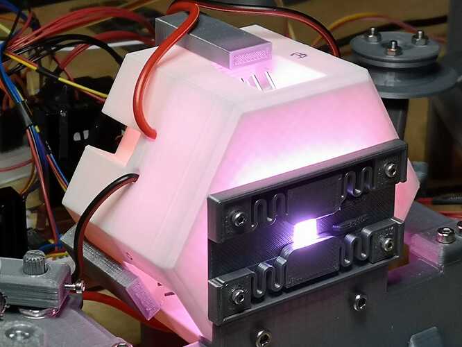
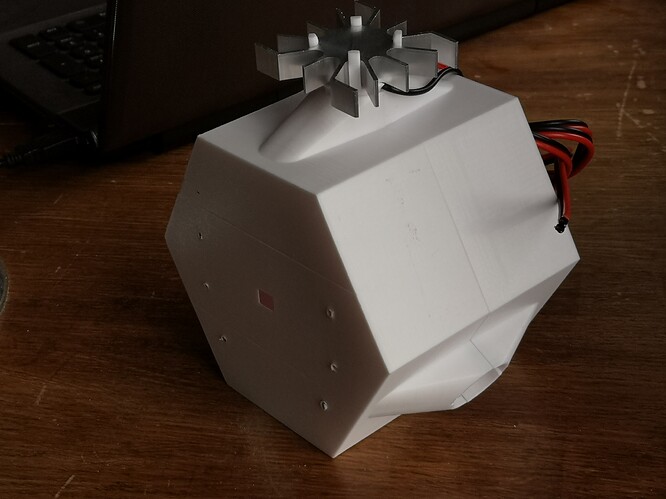
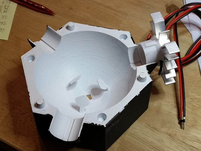
… well, the 3D printing takes about 2 days on my printer, which is a cheap Anet A8 (200 €).
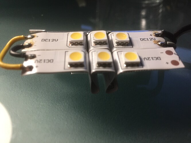
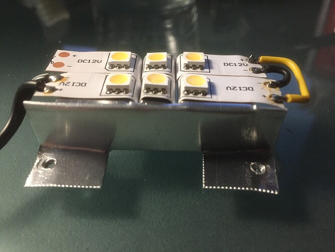
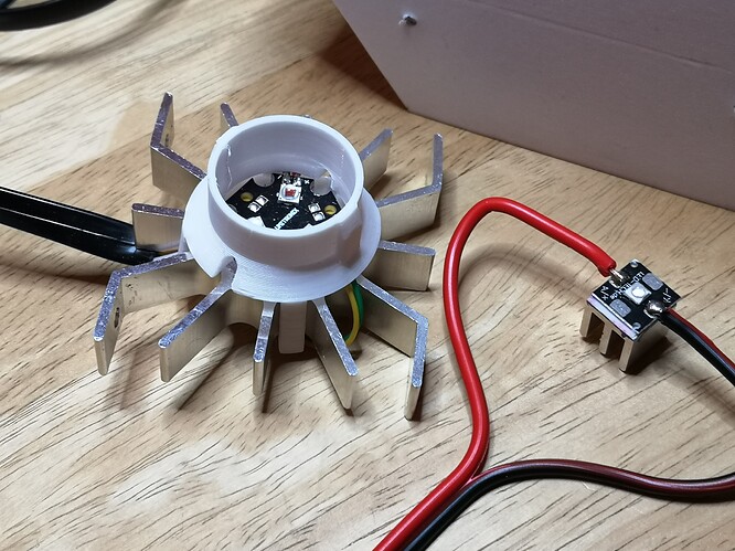
Add about half an hour of spray-painting the inner side of the sphere. Assembly is rather simple and might be done in a few hours. You take the 3 LEDs with their squared PCB and solder wires to the pads of the PCB. Then an adhesive pad is used to glue the LED-PCB and the heat sink together. I guess you will need at most an hour for this task. The next step is to insert the LED together with the supply wires into the grooves of a half unit.
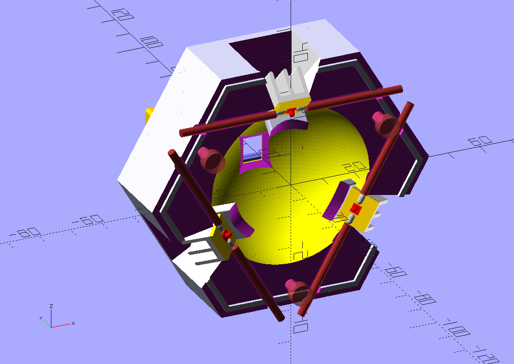
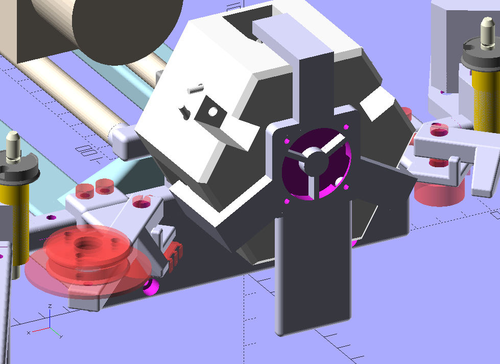
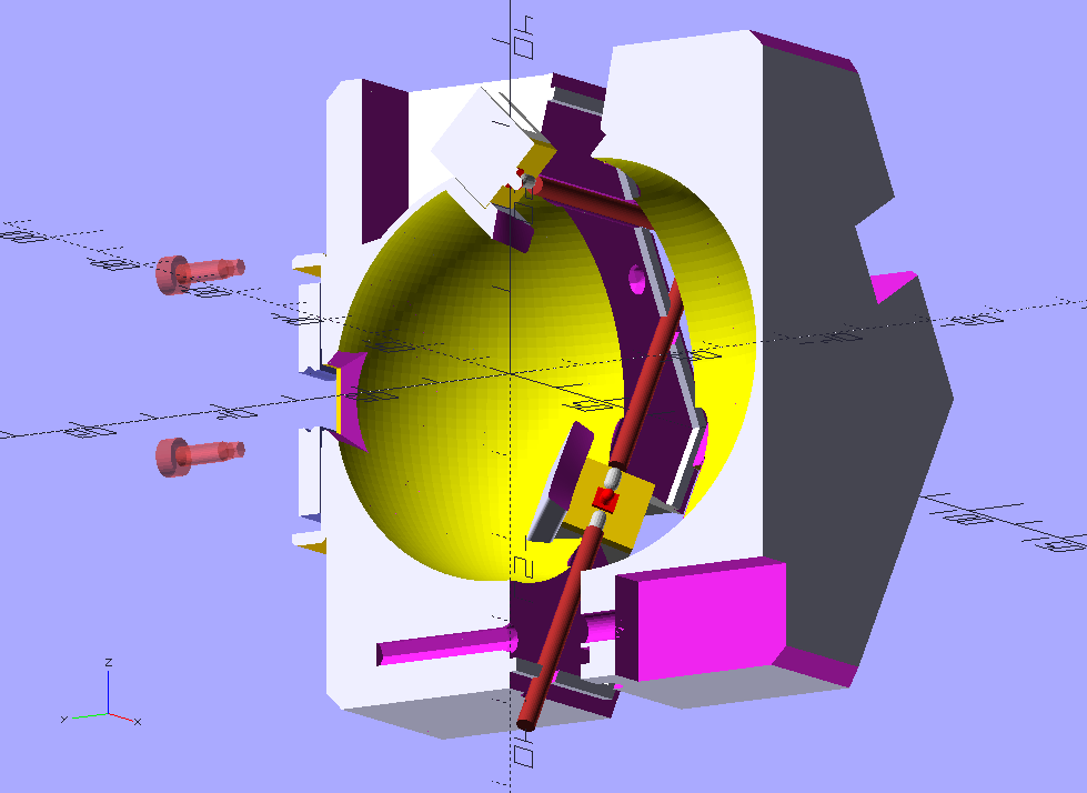
This cut-away rendering shows how this done (I hope  ). The straight dark red lines are the wires:
Once that is done, the back and front halfs of the unit are pushed together. There’s a rim on one half and a corresponding grove on the other half, so some sort of snap-fit is achieved. Just to be sure, 3 long M3-screws are used (on the bottom part of the above cut, you can see the channel of these screws). All that doesn’t take too much time and that is the final assembly step.
With respect to costs: each LED-unit is composed of
- one Osram LED on a 10x10 mm square PCB, about 3 € (I am in Europe)
- heat conducting pad, about 10 cents
- 10 x 10 x 10 mm heat sink, about 1 €
So that would be about 4 € per LED-unit, so a total of 12 € for the LEDs. PLA-material for printing the sphere is negligible, probably less than a 2 €, while printing time is not (2x days with my printer).
The real costs are probably hidden in the electronics which drive the LEDs - these are programmable constant current sources. For my setup, I did not want to use PWM-type of LED-dimming (which usual LED-strips do).
However, I can’t really give an estimate on these costs, since I used parts I had already available. Basically, the electronics consists of two dual DAC (10 bit resolution, SPI-interface), a quad operational amplifier and 4 power fets on heat sinks. Part costs might be around 30 €, at most. I created a first (through-hole) version of a PCB for this unit, but that circuit design still needs some improvements.
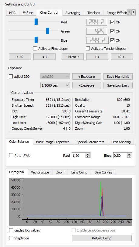
Which brings me to your second question, the software. I do develop my own software. As my system splits the work onto three processors, it depends a little bit on the processor which software environment I am using.
First, there’s an Arduino Nano which drives four stepper motors, reads potentiometer values from two tension control arms and adjust the LED-currents to the requested values. This part of the software uses the Arduino-IDE (so essentially C++).
The Arduino gets its commands via a serial interface from a Raspberry Pi 4. Connected to this Raspberry Pi is also the camera used to scan the film. It features a v1-sensor chip and a Schneider Componon-S 50mm as lens. Both camera and serial communication with the Arduino are handled by a server running on the Raspberry Pi, written in plain Python 3.6.
This setup is very similar to other people which utilized a Raspberry Pi for telecine. A special library which is utilzed in the server software is the “picamera”-library. The server is able to stream low-res images (800x600) @ 38 fps, but drops down to a few frames per second for the highest resolution and color definition.
Anyway, I do use a special version of the picamera library, which is able to handle lens shading compensation. This is absolutely necessary if - as I did - you change the lens of the camera (remark: via lens shading compensation, a partial compensation of color shifts can be achieved which are introduced by a lens change. Turned out to be sufficient for my needs in case of the (older) v1-camera. The newer v2-cameras become unusable if you change the lens).
Well, the Raspberry Pi server delivers a camera stream plus additional camera data to a client software which is running on a rather fast Win10 machine. This software is also written in Python 3.6 and uses a few additional libraries. Specifically,
- Qt-bindings (PyQt5) for the graphical user interface
- pyqtgraph for graphical displays like histogram and vectorscope
- cv2 for a lot of image processing
- and finally numpy for the rest
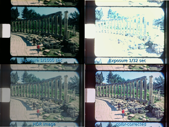
This client software can request an exposure stack from the Raspberry Pi and essentially stores the original .jpg-files of the Raspberry Pi camera on disk for later processing.
The next piece of software is a simple Python script which does the exposure fusion (Exposure Fusion). While cv2 has its own implementation, I actually opted to implement this by myself in order to have more control over the internal workings. This script takes different exposures of the same frame and combines them into a single intermediate, stored again as 48-bit RGB image on disk.
Note that this exposure-fused image is not a real HDR-image. Actually, the client software mentioned above has the subroutines available to calculate real HDR imagery (which consists of estimating the gain-curves for the camera, and than combine the exposure stack into a real HDR-image), but I did not find a satisfactory way to tone-map the resulting HDR-movie into a normal 24bit RGB-stream. So I settled with the exposure-fusion algorithm of Mertens.
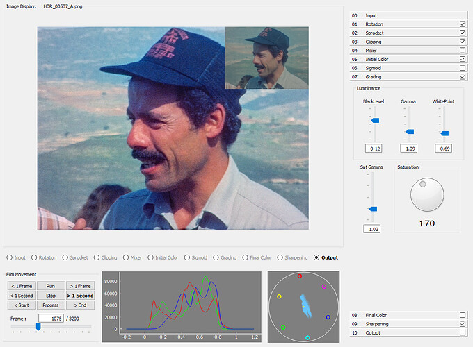
Anyway, the 48-bit pseudo-HDR images are than read by my third piece of software, also written in Python 3.6 + PyQt5 + pyqtgraph + cv2 + numpy, which allows me to do sprocket registration and various color and other adjustments. Here’s a screenshot of this program to give you some idea:
The 48-bit intermediate image can be seen in the top-right corner of the frame display for reference. At this point in time, the software works stable, albeit a little bit slow. Also, too much experiments left their traces in the code. So I am planning a total rewrite of this software once I think it has reached its final form…
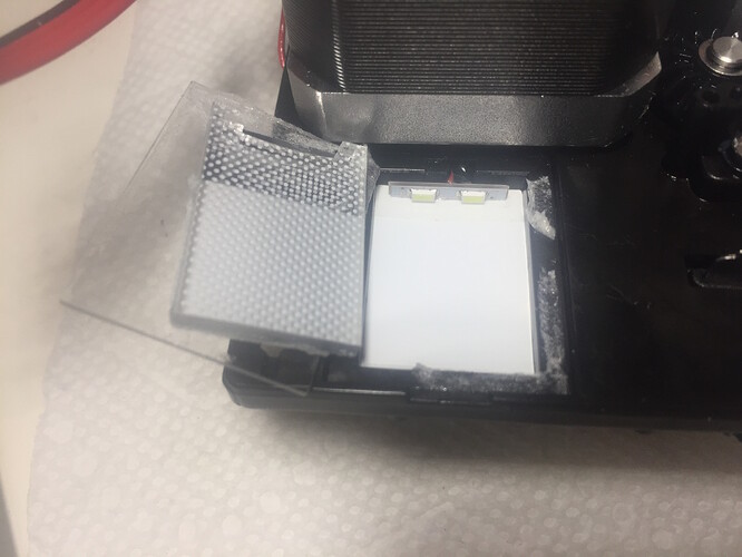
@mbaur: this teardown is interesting! Because: this setup is very similar to illumination setups used in LCD-screens (edge-lid backlights). The white dots which are visible are used to “extract” the light from the sideways placed LEDs perpendicular into the surface to be illuminated. Sometimes (in LCDs), these dots do vary slightly across the surface to counterbalance the otherwise uneven light distribution of such an setup. So actually, ripping apart an old LCD screen to get the diffusor might be an interesting basis for some experiments with a brand new telecine lamp! 
