My 8mm 3-inch reel scanner, a learning experience

First thread, though I’ve been reading the forums for a fair bit without registering. I wish that I had found this forum months ago. Here you have a treasure trove of research, test results and lived experience. There are other resources out there, but most are stale with discussions that started and ended in the 2000s or 2010s.

In late October I caught the film-scanning bug. My grandparents aren’t getting any younger and both sides of my family have bequeathed me their 8mm collections, mostly 3-inch reels of regular 8. I desperately wanted to scan at least one reel before Thanksgiving rolled around, so I looked at what was commercially available. Everything I found was either too expensive or garbage quality (Wolverine clones). Nothing in the middle; nothing around the $500 to $1000 range. I looked into paying a third party to scan the whole collection, but the average quote would have been in the $2000 range. Trapped between low-end consumer and enterprise-level equipment, what is an engineer to do?

Like so many others, I set out to design my own scanner. Like so many others, it would use a Raspberry Pi and an attached camera module. Unlike most others, I intended to make all non-moving parts printable on an average-sized 3D printer (anything with a 220mm or larger bed). No borrowing parts from projectors, no hacksawing metal tubes, tapping aluminum extrusions or other fancy metal work. Just some metric screws, low-quality bearings and stepper motors stolen from the carcass of an Ender 3, a thin LED backlight and a cheap Chinese M12 lens. I only wanted to scan 3-inch reels for now and I didn’t want to spend more than $100 on parts.


https://twitter.com/mark_wilhelm/status/1577030189221294080?s=20&t=s5ZLurWFTExbkKOAvc8CxA

Within a week I had a prototype that spun! I tried using an Adafruit motor hat for the Pi, but I hated it. It was loud, slow and dangerous. Without adjustable motor current, some of my spare stepper motors overheated when holding position. I was able to work around most of the board’s limitations by purchasing Adafruit’s recommended steppers, tweaking Pi settings to increase I2C refresh rate, and refactoring my code over and over. Stepper noise/chatter and lack of motion smoothness, with or without microstepping, was impossible to overcome (the Pi makes a poor motor controller), but I was just getting started. I still thought I could make my self-imposed Thanksgiving deadline.


https://twitter.com/mark_wilhelm/status/1580340356595400704?s=20&t=s5ZLurWFTExbkKOAvc8CxA

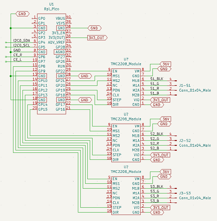
I iterated upon the design: adjusting the position of motors and rollers, settling on the HQ camera module, testing a bunch of cheap M12 lenses, and refining the gate. The LED backlight was working great, except the HQ camera AWB algo was choosing the wrong color temp. I found suggestions on this forum to tweak the tuning file to disable AWB and it worked, thanks cpixip! I abandoned the Adafruit motor board and adopted a generic GRBL-based CNC control board. This allowed me to use TMC2208 motor drivers, which solved the noise, heat and smoothness issues all in one fell swoop. Praise Trinamic! Unfortunately for me, GRBL is designed to enable all motors simultaneously and my design relied upon the latent resistance of one deenergized stepper. Deterred, but not demoralized, I quickly moved on to another option.

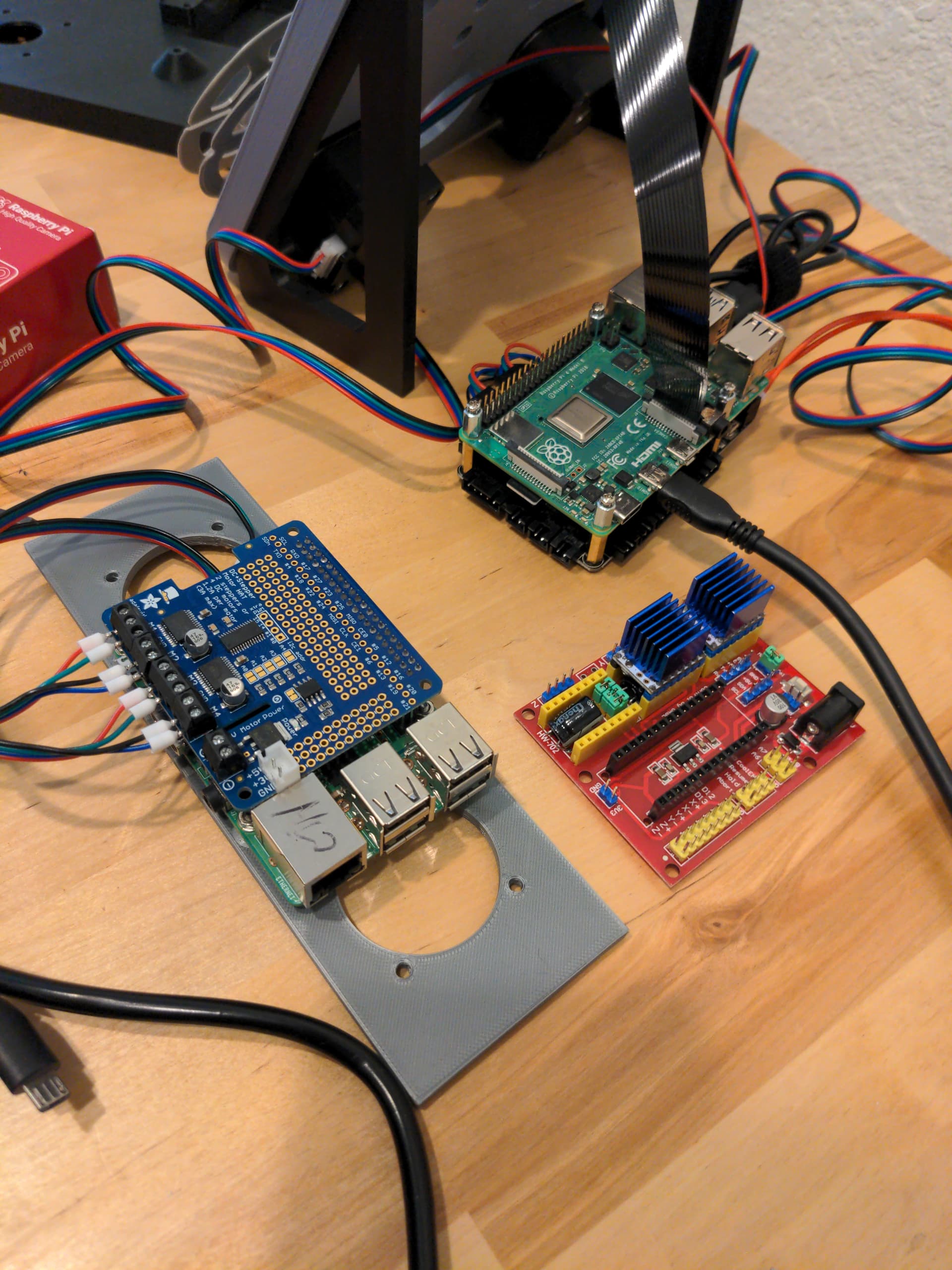
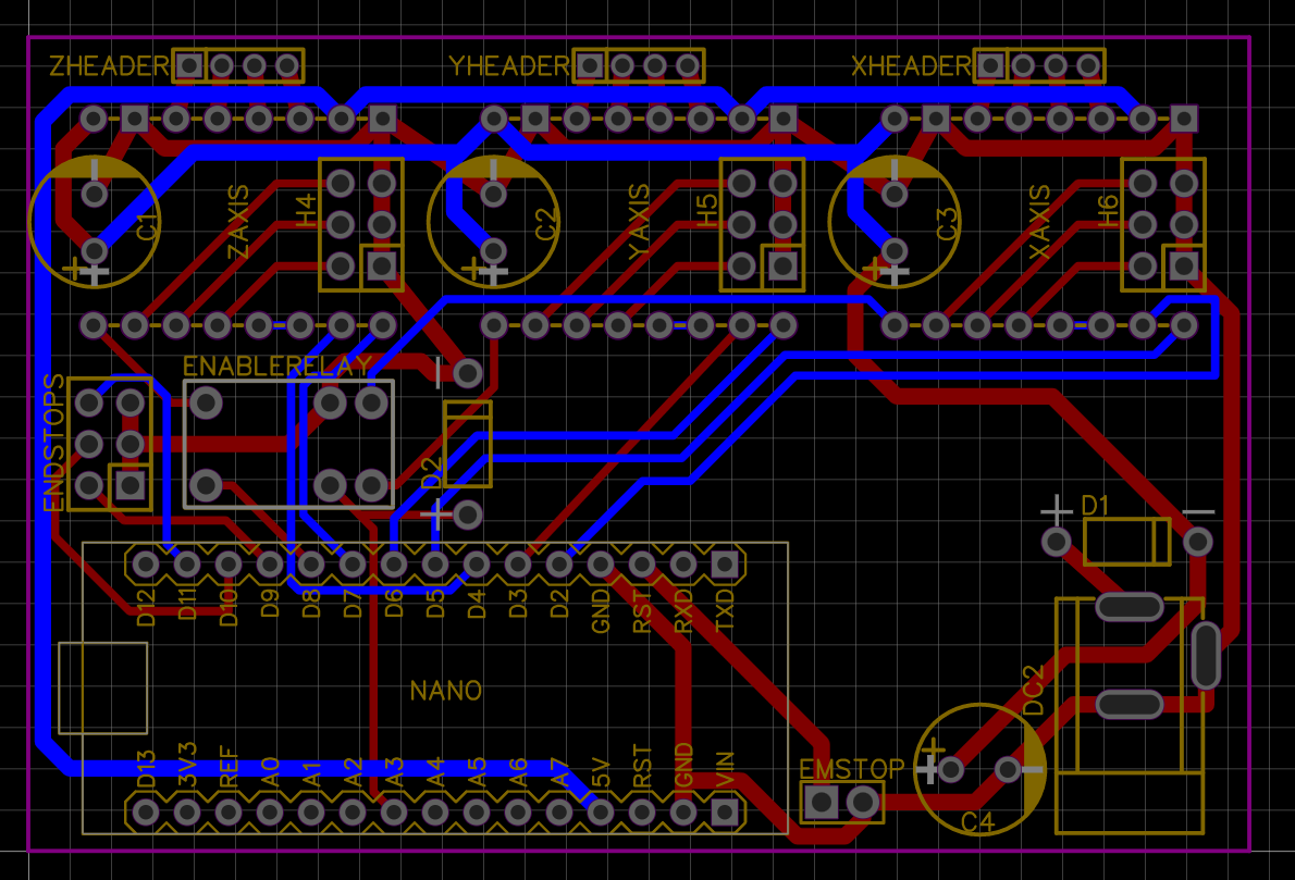
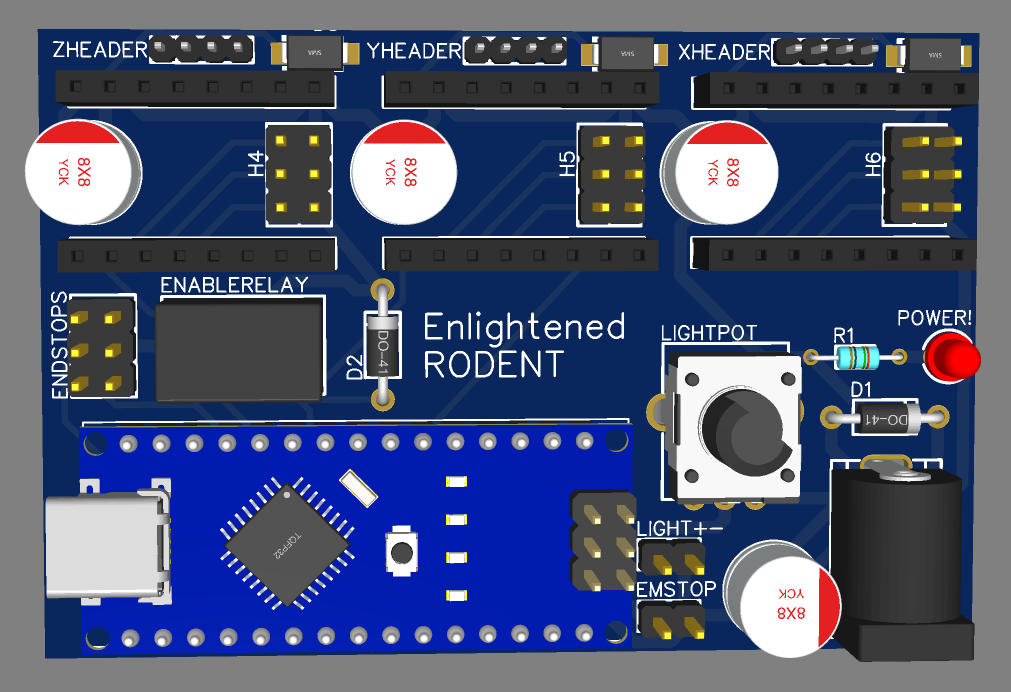
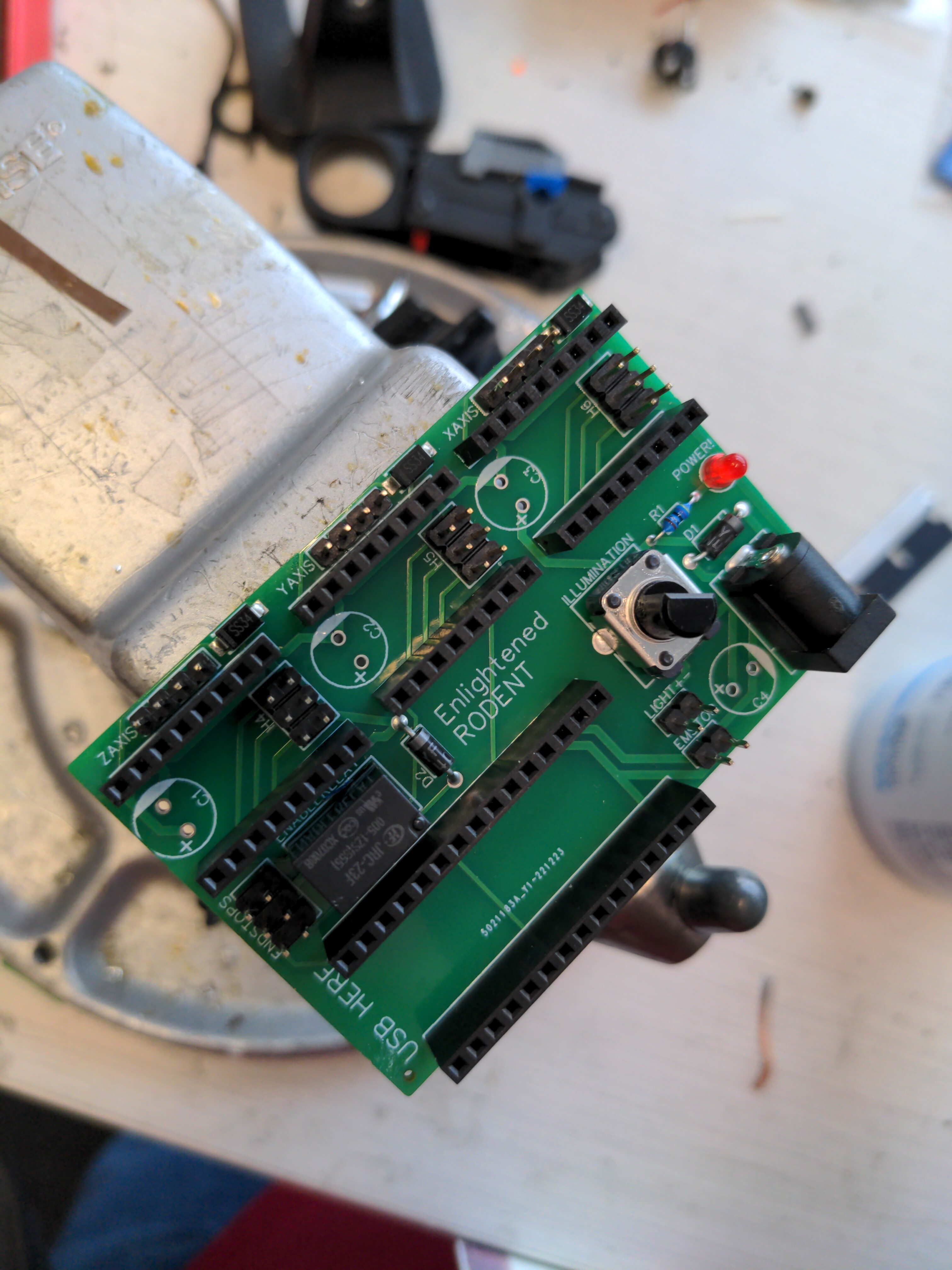
In my third round of designs, I focused on perfecting the gate and switching to a BigTreeTech SKR Pico for motor control. The SKR Pico runs Klipper, which was a new challenge. A lot of time was spent figuring out the Moonraker/Klippy API. I had a tiny PCB made for more safely connecting up the LED backlight. I also sent off the gate design to be printed in resin. Turns out a typical FDM 3D printer isn’t the right tool for some design challenges; who would have guessed? Thanksgiving was creeping closer and my code went through three major revisions, eventually converging on a double-threaded approach: one thread for motor control, one thread for OpenCV inspection and libcamera capture. That concept probably sounds awfully old-hat to a lot of people here, but it took a while for me to accomplish.

Now, with Thanksgiving breathing down my neck, did I have a working film scanner? Yes, but no. The lens I had built the entire thing around was a massive weak point and I hadn’t bothered to really look at alternatives the entire time I was developing the system. To be honest, bigger and better lenses just didn’t fit within my narrow requirements, so I ignored them. Now, as I spent hours struggling with fringe motor control issues, I realized the system’s output just wouldn’t be worth keeping. I needed to go back to the drawing board, but I had no time left on the clock.

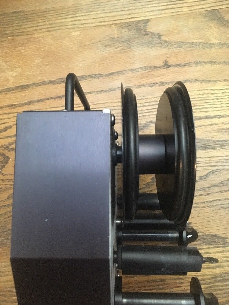
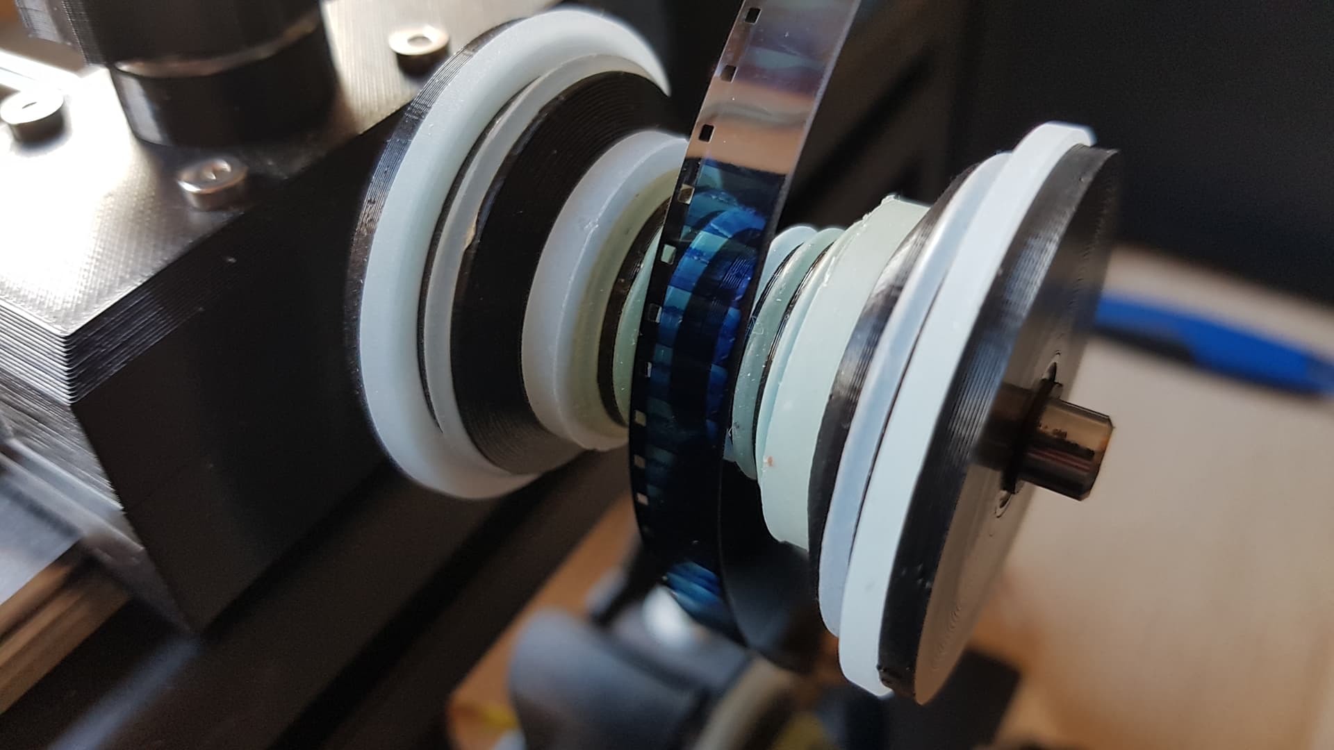
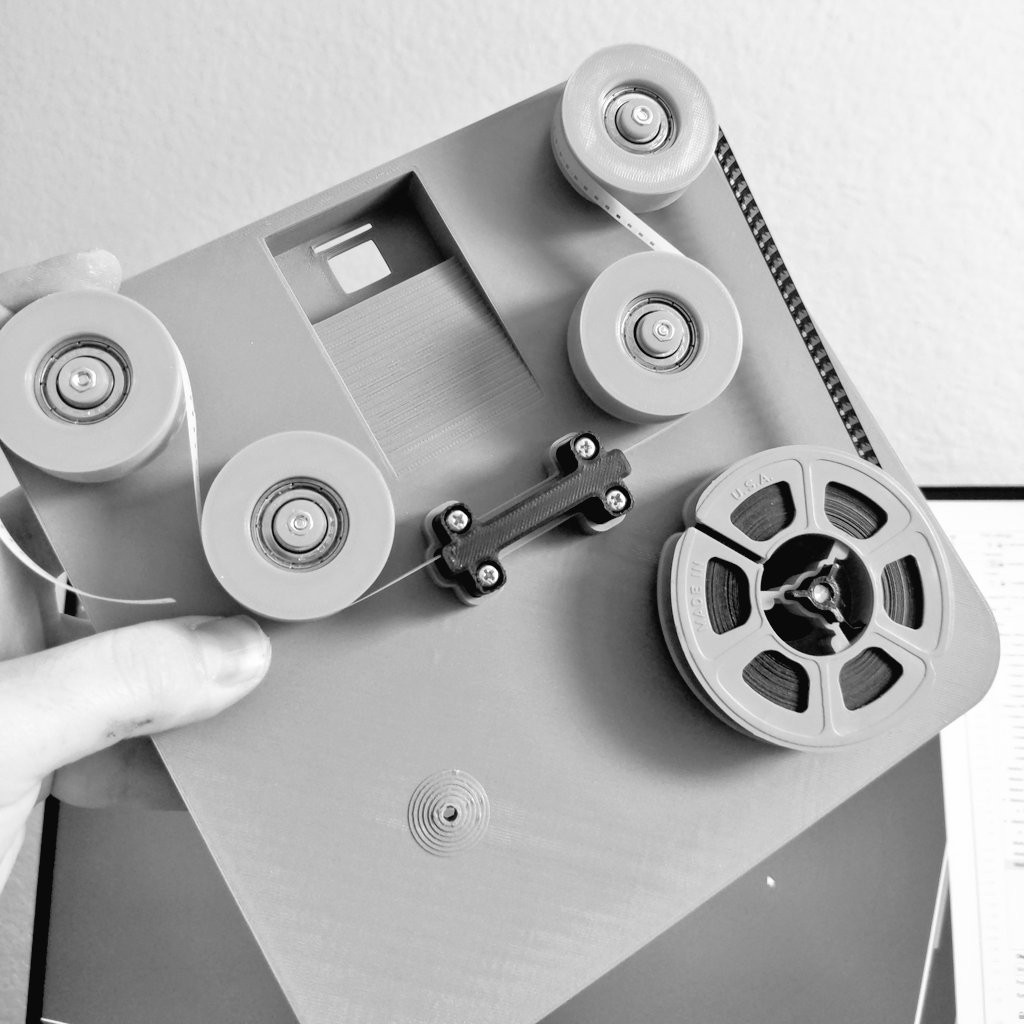
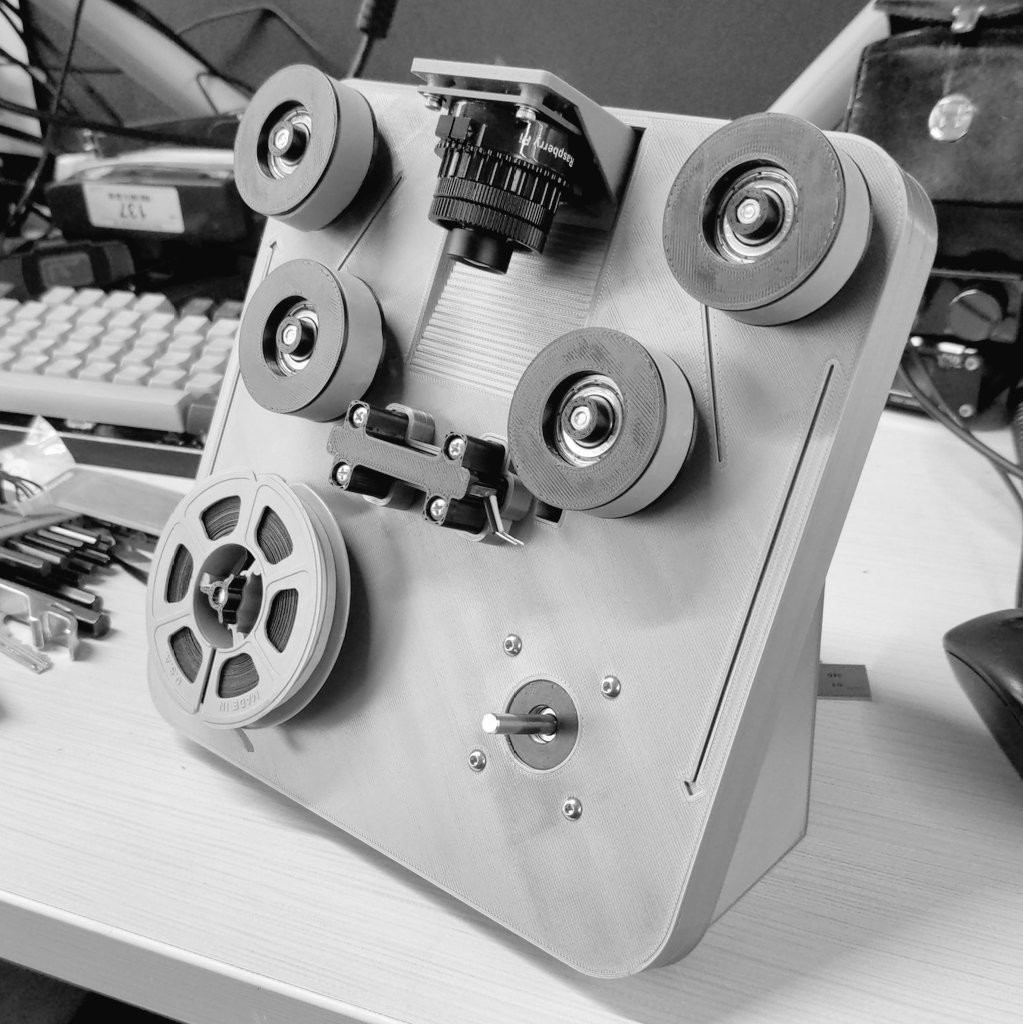
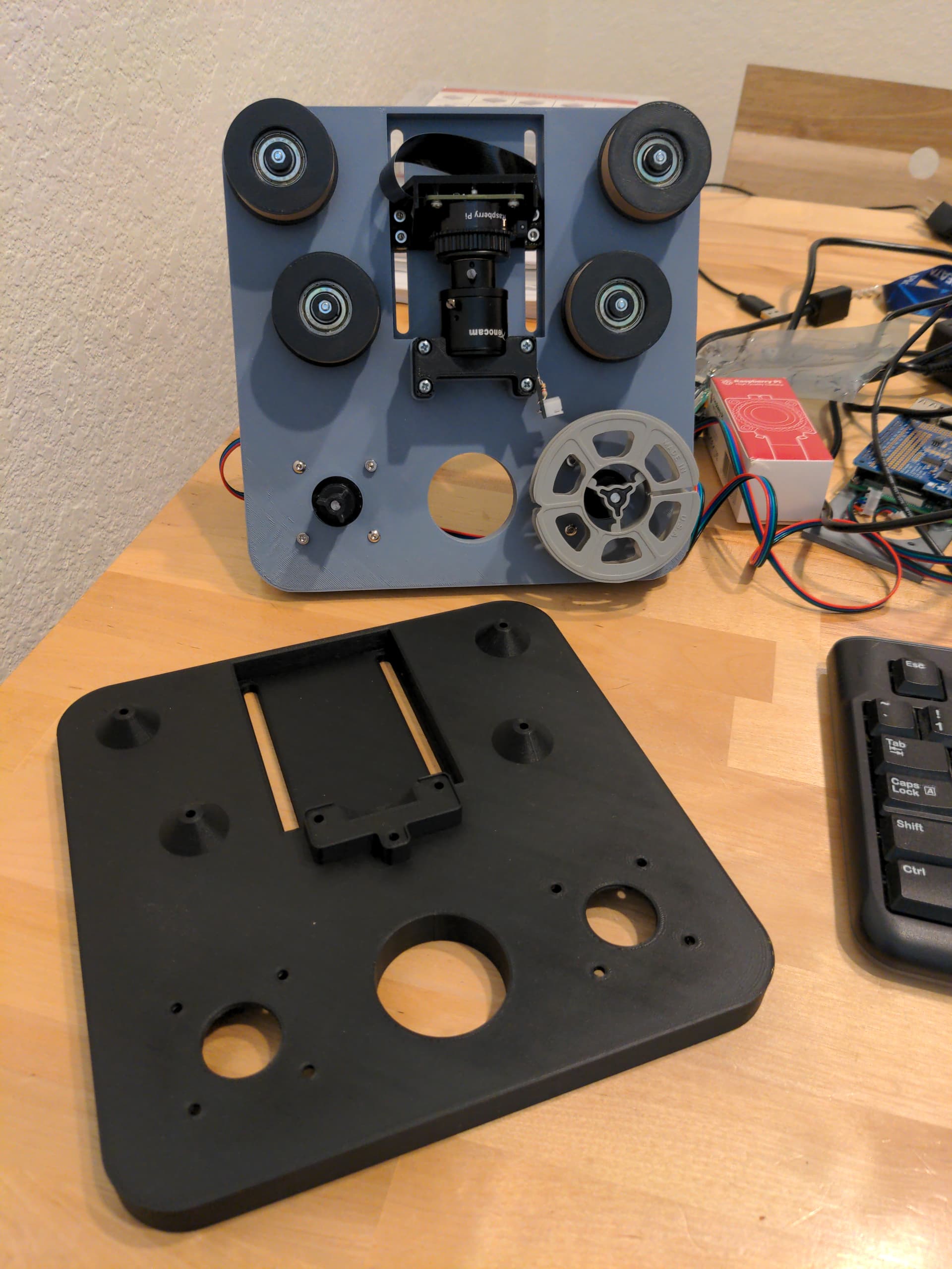
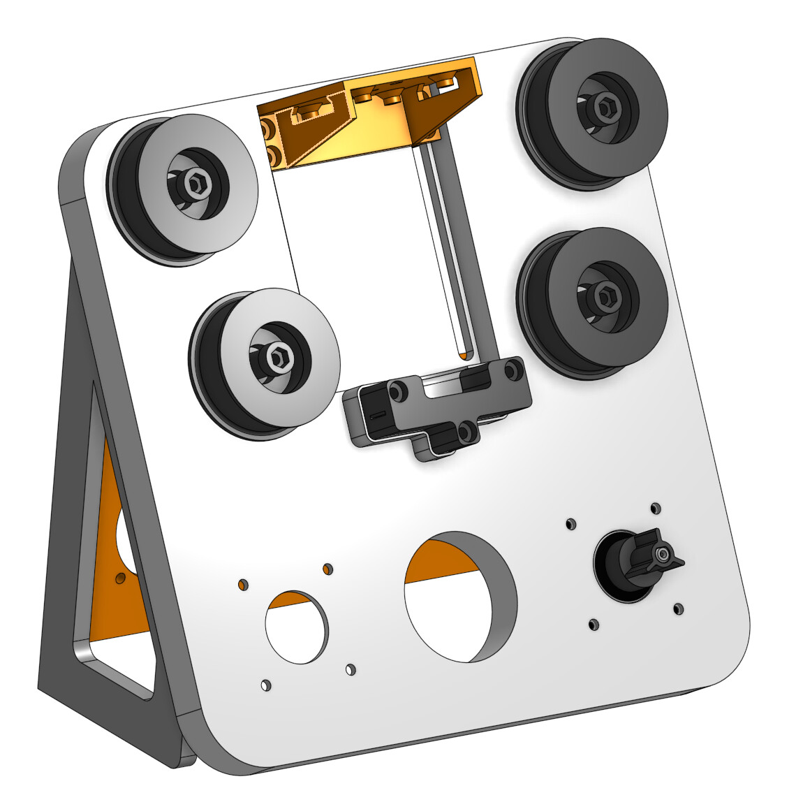
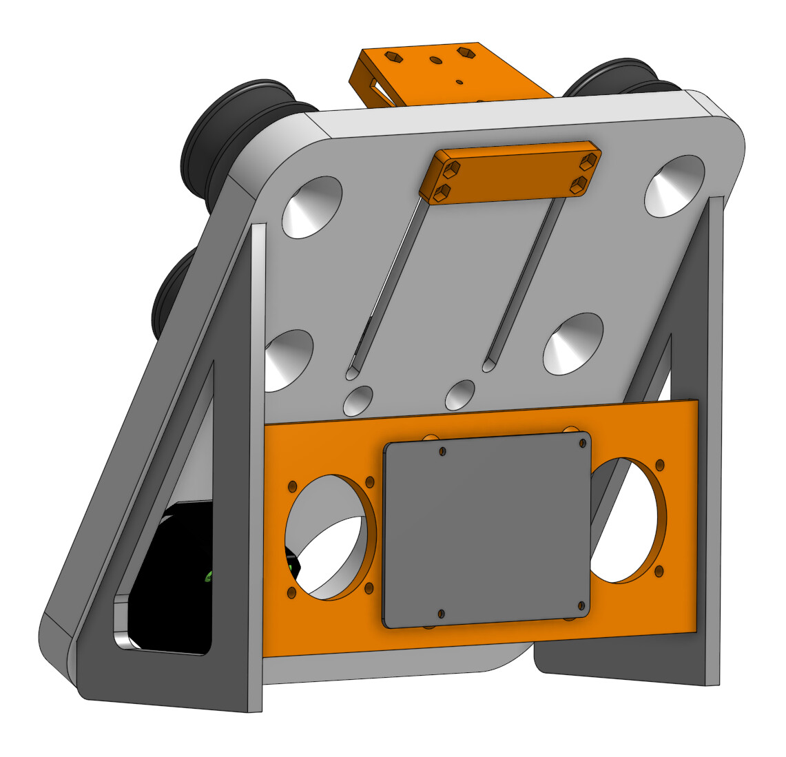
Here’s some pictures of the last version of my 8mm scanner before I stopped working on it as of November 2022. I’m not happy with it and I don’t think I’ll release the files. I had plans to extend the capacity of the design past 3-inch reels by adding wings. I can also extend the camera track to accommodate a much better lens, like the Componon or Nikkor… but it’s not really my focus right now.


Again, to reiterate: I wish I had found this forum sooner. Much of the work I was doing had already been done by individuals here, and the same roadblocks I was running into they had encountered and conquered. I learned a ton working on this project, so now it’s time to start over.

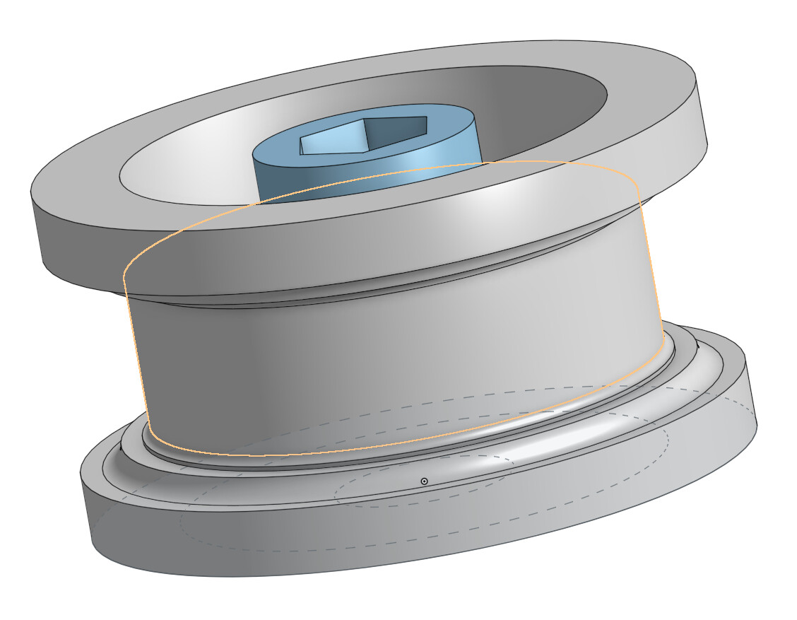
I ran the numbers and I know now that if I break a few of my self-imposed rules, I can make something much better. I have already begun working on a new design and there’s a sketch in OnShape calling my name. It relies on a few parts from the OpenBuilds catalog. :wink:

Hope I can edit this post after I post it, not sure if the images will appear properly. EDIT: Oh good, I can.

8 Likes

Great work Mark! Even if it isn’t what you desired for your final design. I have some questions for you:
Why the large diameter roller wheels? and
What is the different colored material on the surface of the wheel where the film rides?

Thanks!

Junker,

That colored band on the rollers you noticed is actually a rubber band. I couldn’t afford proper film cleaning rollers (good luck finding them in stock), but I assumed that fresh rubber would be a better surface for film to ride on than raw PLA or PETG. All the old reels I have are kept spooled up by old, dried-up rubber bands and they show no obvious signs of damage. If there’s a good reason to avoid rubber rollers, I’d be happy to hear about it!

I made the rollers that large of a diameter so that the wide rubber bands I purchased were stretched, but not stretched tightly. The brand is Sterling and the size code is 82 (2.5 inches by 0.5 inches).

I’ll probably redesign the rollers to be tiered/stepped because the design you see in the photos/screenshots had issues with film falling off when tension was released.

EDIT: Just daydreaming, but if I had access to a machine lathe, I might attempt to make smaller rollers out of brass.

Clever! According this site, the durometer (hardness) of Urethane PTR rollers is 28A-34A. And here it mentions a rubber band having a durometer of about 35A. So in that regard, you are right on target without having to spend $100 each for PTR rollers! Do rubber bands have the same “stickiness”? I don’t know, but it would seem so.

Thanks for the additional information, I did not consider researching the hardness of the different materials. I would not assume the rubber band is doing an exceptional job for anything but satisfying my guilty conscience. I can’t stand the idea of running my family’s film across an unpolished hard surface that could contribute to further degradation.

The rubber bands are quite soft and give the roller enough grip so the film rotates them evenly instead of skipping/sliding past. I have not run enough film over my rollers to tell if it’s having a cleaning effect or even an abrasive effect, but no residue has been left on them so far and I haven’t noticed the bands change color or show signs of collecting particles.

I could probably 3D print a better roller with TPU on the edges that contact the film, but I’ve never tried using the material before and it has a reputation of being difficult to print with.

I would throw a couple of o-rings on the rollers instead of trying to print with a finicky material. Kind of like this:

1 Like

A bit like this which allows you to switch between different formats.
Very nice work,Mark.

1 Like

@Mark welcome, and great posting.
Suggestion to improve the results of the TMC2208 is to implement some linear speed, the results are amazing. The best reference I found is the Atmel Whitepaper and I implemented it successfully with Arduino and Pico, probably the Raspberry Pi will not do. The TMC2208 are easy enough to drive.

Some of the constant themes in the forum for stop-motion builds are stepper and light. I am thinking if there will be enough interest to ‘productize’ a ready-to-go simple board with a Pico, stepper drivers, and control light, to be paired with a good quality LED in a separate driver-carrier.

1 Like

@Roland That’s my current plan, except for now I’m focusing entirely on 8mm.

@PM490 Thanks for the suggestion! I’ll take a look at that whitepaper.

I’m working on a custom version of the venerable GRBL CNC v4 shield, with an additional relay to toggle between X and Y motors enabled (since that’s not a normal feature of GRBL). I’m going to use Z axis in my next design for coarse lens focusing, moving the camera module up and down before fine focusing by hand. The relay is switched by GRBL’s “coolant enable” pin. I see no reason why I couldn’t add a header for powering a light source off of the stepper driver supply rail. Could even add a potentiometer for adjusting brightness, since there’s some space left in the center.

I was not familiar with the GRBL CNC v4 shield, but did look into other available 3D printer boards as alternatives. Instead went with own design, the TMC2208 are easy to wire (currently I have them in a protoboard for testing).

After a looking at the schematic of the GRBL v4, and if you are doing a custom board, consider that also it does not allow the controller to change the micro-stepping setting. That may not be relevant in your case, but I am using geared stepper motors, which I like to run at different MS settings.

Don’t understand the purpose of the relay. What you can do is cut the Enable (pin 9 of the TMC2208 carrier) and run a line to a nano digital output. Here is the draft schematic for the stepper control portion I have running on the protoboard (with a Pico).

That’s one approach.

There is lots of information on the forum on light sources, light control, and multi-exposure stacking (Mertens). One approach is to change the sensor exposure time, another is to change the intensity of the light. What I was describing above is using a DAC for controlling light intensity.

Didn’t see you were using the Nano, that’s where the implementation of the linear speed will work.

Admittedly, I am using the GRBL firmware as a crutch so I don’t have to write my own. I believe GRBL already implements many advanced motion techniques, including the one you introduced me to earlier (linear acceleration). Apparently, if you want to query the controller or ask it to take an action, it can respond incredibly quickly even if it’s processing a complex movement. Honestly GRBL is simultaneously overkill and inappropriate for our film scanning applications, but here I am playing tricks with it to skip a development step. :skull:

I am going to have at least one of these modified GRBL boards made, but I think I see your point, @PM490. Has someone already published an open-source motion controller board for the film scanning niche? Are there enough people interested in such a board? What would the minimum spec be? Three motor driver sockets, an 8-bit microcontroller, light control, endstops/limit switches? That’s the minimum I think I would need.

Initially thought you were using the board alone (not the gbrl sketch). Now it makes sense using the existing pins (softwarewise). And yes, GRBL firmware does use these stepper optimization algorithms.

That + light is what I am thinking

Quick update, still need to fix the pin headers for the motors (wrong pin pitch), but here’s a quick render of the board as it stands. Will probably order one this week.

Ignore the capacitor 3D models, they’re through-hole electrolytics and the leads have to be bent 90 degrees to lay them flat against the board in order to fit the motor driver sticks above them. That’s why there’s a large gap between them and the microstepping jumper headers.

Came across this board, and interesting form factor, but for film scanning it would need a slot for the camera flat-cable.

I just received my boards from China today! Very exciting to get two of each fully assembled (three unassembled boards).

Got some testing to do but might be moving soon, so I may have to put this side project on hold for a month or two until I’m settled again.

1 Like