My all format scanner

No problem. Here is the support that will provide very good rigidity. The pulley moves freely along the axis, which allows for good guidance regardless of the film format. The printed support itself does not move; it is firmly screwed onto the aluminum profile.
Attached is the .stl file in case you want to try printing it.

Poulie guidage v3.stl (55.9 KB)

1 Like

Am I getting it right? You mean that pulley is not locked on the axis at all? Or it is locked tight and can be repositioned when the film gauge is changed?

The pulley is free to move along the shaft. It self-centers automatically.

1 Like

Dear Roland,

Just want to thank you again for advices, as you see I’m moving forward and this week I should finalize motion block and step into drive assembly and laser fiddling. Rollers work super smooth.

Waiting for SLP controller now to step into lighting fixture.

2 Likes

Wow
 awesome. Glad to see you’re making progress.
Here are two parts that will let you, if you want, make a film press like mine.
The film guides are made from MGN5 rails (you need to polish the inside thoroughly until it has a “chrome-like” finish).
For the lateral movement of the pressers, I used 10 cm MGN12C rails.
Always available if you have any questions. :slight_smile:

Guides films sans pont v11.zip (21.8 KB)

Edit:
I forgot—so that your two presser rails are exactly the same height relative to each other, and thus your film is perfectly perpendicular to the camera, you can add a shim to each of the two rear blocks if needed.

Cales épaisseurs v1.zip (7.4 KB)

1 Like

Looking at the scheme it feels like film guides are from MGN5 rails. I’ve already made mine from MGN8 but maybe I’ll switch to MGN5 to keep the profile aligned to ventilation fixture. The pressing rails supposed to be made w MGN12 rails exactly like yours)

You’re right—that was my mistake. It’s MGN5.
I’m worried the MGN8 might have grooves that are too high and the film won’t be guided enough. But we’ll see.

I’ve back ordered MGN5 fixture to compare, meanwhile I’ll re-engineer assembly for MGN8.

I wanted to ask about structural approach - you’ve mentioned that “ The motor speed is regulated by the laser pulse detection frequency” which confuses my logic for the microcontroller programming. Can you clarify if the wind speed of motors is continuous and steady based on pre set rpm or you have certain amount of rotation between the laser pulses pre-programmed?

Here we’re really getting into the technical side, and my English might make me misunderstand or express myself poorly.
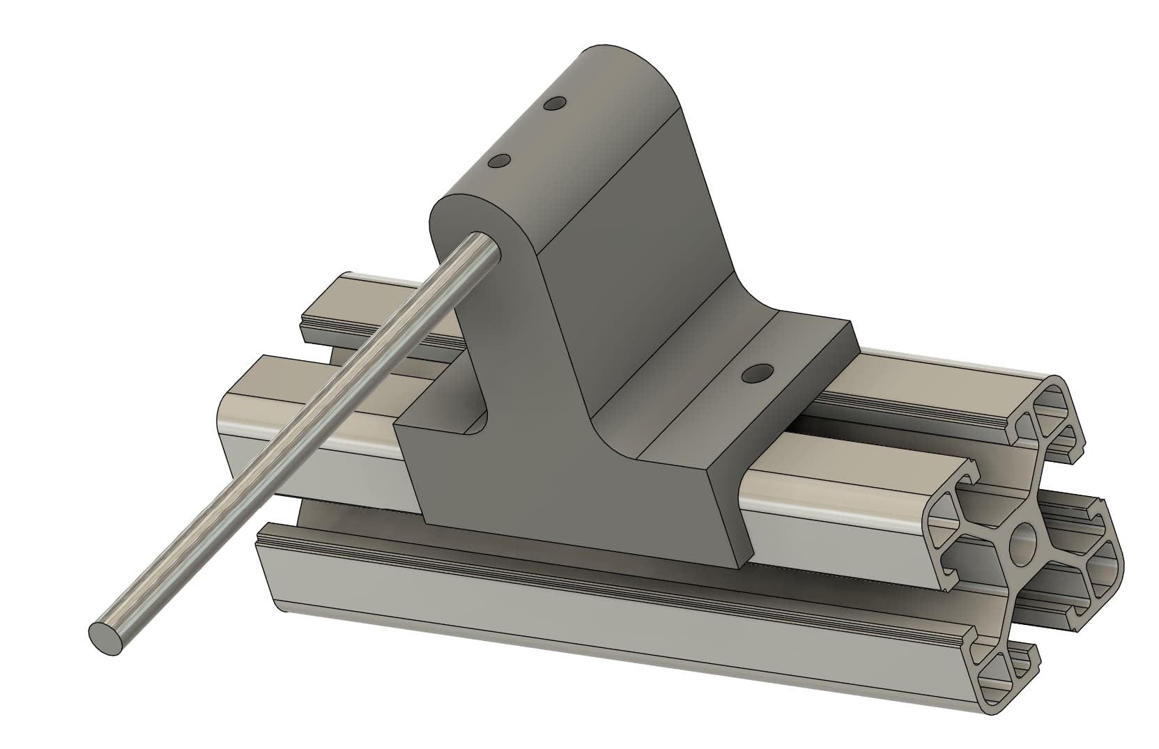
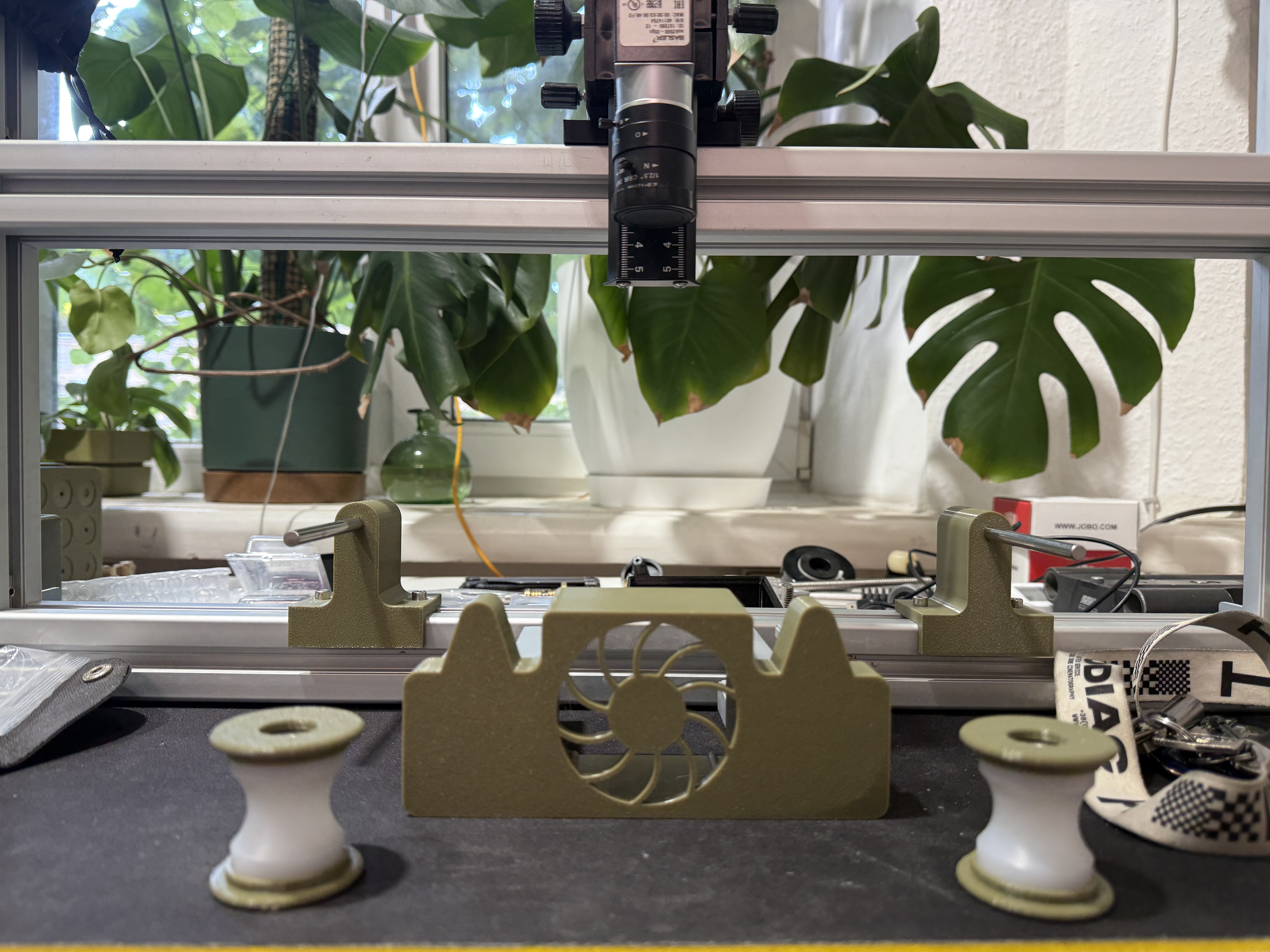
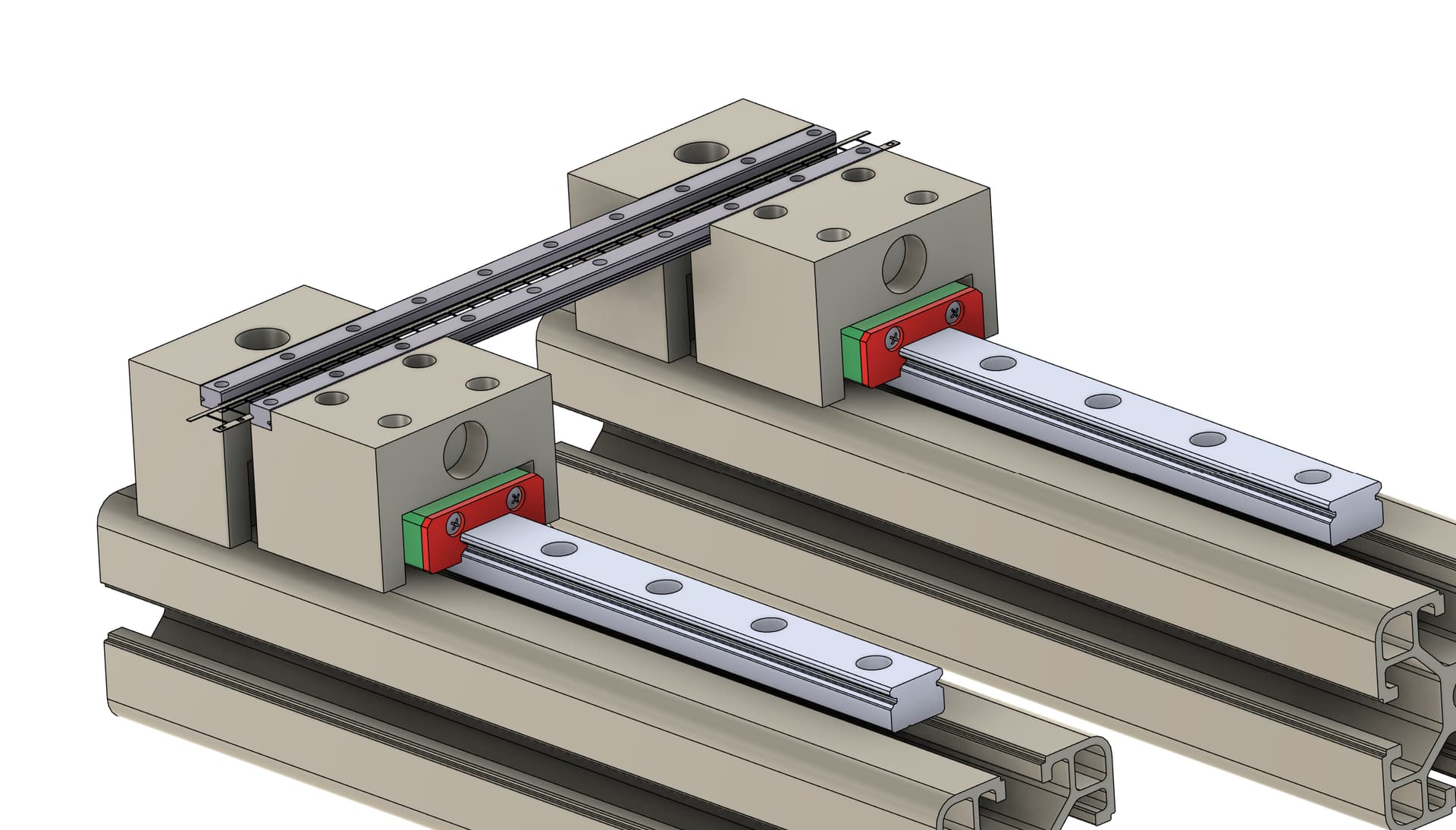
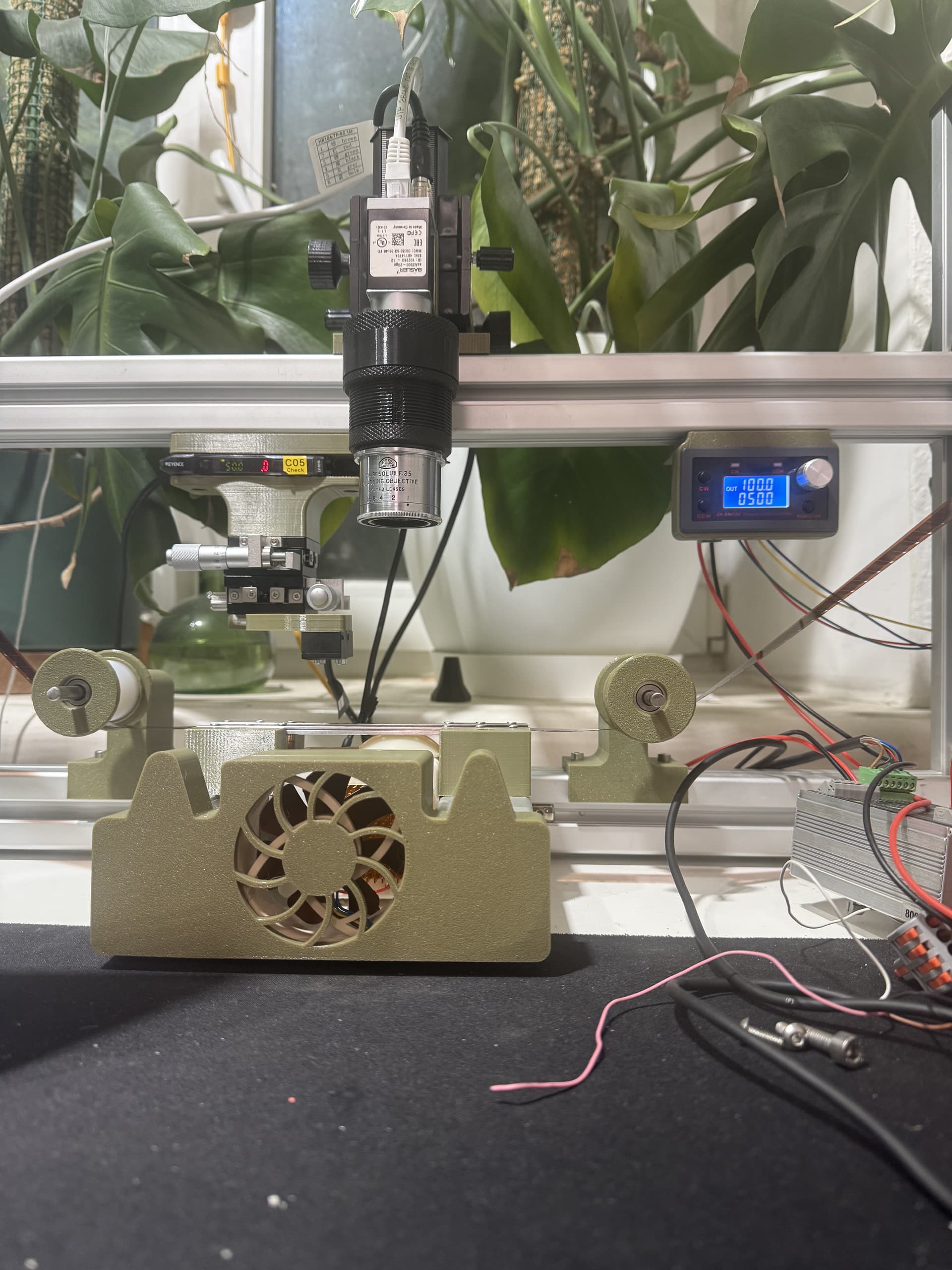
I think that if I want to be at least a bit clear, I need to show you how my scanner is designed:

Here is the wiring of the box at the back, which provides power and acts as a “hub” for the motors, lighting, ventilation, and the laser:
Schematic_Schéma de branchement pour boitier arriÚre_2023-07-30.pdf (55.3 KB)

Then there is the control box, which manages and coordinates all of these components:
Schematic_Schéma pour boitier de commande avant_2023-07-30.pdf (78.2 KB)

And finally, there is the program that runs on the Arduino, which brings us back to your question:

Basically, each perforation sends a pulse to the Teensy, each pulse triggers this method, and the regulation is carried out with this code, each time a new pulse is received:


// === CAPTEUR LASER ===
void checkPerf() {
digitalWrite(CamShoot, HIGH);
timerDelayCam.begin(temporisateurCam, 200);

// Mise à jour de la durée du flash selon le potentiomÚtre
flashDuration = map(analogRead(potFlashDuration), 0, 1023, 50, 1500);

// Calcul du temps écoulé entre deux images
endTime = millis();
frameInterval = endTime - startTime;
startTime = endTime;

// Calcul du FPS actuel et envoi au filtre de lissage + affichage
float currentFPS = (frameInterval > 0) ? (1000.0 / frameInterval) : 0;
computeSmoothedFPS(currentFPS,false);

// RĂ©gulation de la vitesse moteur en fonction de l’erreur sur l’intervalle cible
float targetInterval = (imagesPerSecond > 0) ? (1000.0 / imagesPerSecond) : 0;
float error = frameInterval - targetInterval;
float correction = computeCorrection(error);

currentMotorSpeed += correction;
currentMotorSpeed = constrain(currentMotorSpeed, 50, 10000);
if (targetInterval == 0) currentMotorSpeed = 0;

// Application de la vitesse aux moteurs selon l’état courant
if (currentState == REWIND) {
stepperG.spin(currentMotorSpeed * getInvert());
} else if (currentState == FORWARD) {
stepperD.spin(currentMotorSpeed * getInvert());
}

// Gestion du flash et de la caméra
digitalWrite(Light, HIGH);
}

void temporisateurCam() {
digitalWrite(CamShoot, LOW);
timerflashDuration.begin(timerflash, flashDuration);
timerDelayCam.end();
}

void timerflash() {
digitalWrite(Light, LOW);
timerflashDuration.end();
}

float computeCorrection(float error) {
float Kp = 0.40;
float Ki = 0.02;

if (abs(error) > 0.5) integral += error;
integral = constrain(integral, -50, 50);

float correction = Kp * error + Ki * integral;
return constrain(correction, -120, 120);
}

float computeSmoothedFPS(float newFPS, bool reset){
static const int bufferSize = 10;
static float buffer[bufferSize];
static int index = 0;
static bool filled = false;

// Si reset demandé, vider le buffer et repartir de zéro
if (reset) {
for (int i = 0; i < bufferSize; i++) buffer[i] = 0;
index = 0;
filled = false;
return 0;
}

// Ajouter la valeur seulement si elle est dans une plage raisonnable
if (newFPS > 0 && newFPS < 60) {
buffer[index++] = newFPS;
if (index >= bufferSize) {
index = 0;
filled = true;
}
} else {
// logMessage("[DEBUG] Valeur FPS rejetée : " + String(newFPS)); // Optionnel pour debug
}

// Si le buffer n’est pas encore rempli, ne rien afficher
if (!filled) {
return 0;
}

// Calcul de la moyenne
float sum = 0;
for (int i = 0; i < bufferSize; i++) {
sum += buffer[i];
}
float average = sum / bufferSize;

// Affichage toutes les 500 ms
static unsigned long lastPrint = 0;
if (millis() - lastPrint >= 500) {
logMessage(“[FROM_SCAN_INFO] fsp actuel : " + String(average, 1) + " img/s”);
lastPrint = millis();
}

return average;
}

Tell me if this answers your question.

1 Like

It definitely took me some time to break down :smiley:

First of all - I can’t describe the value you’re providing me regarding your product. This helps so much and delivers even more than I was actually asking. The provided scheme could save me like months of development, so I really appreciate this. Can’t be more grateful.

Secondly it definitely answers my question. It’s a tricky approach with pulse regulated motor speed and I can’t imagine the time spent figuring this out.

My next question however would be regarding the hardware now.
So my idea is to use Basler software and lighting controller to handle flash triggering. Based on the scheme of your assembly I can see that your flash triggers directly from microcontroller separately from Basler camera. So my question is if I’m going the dead way with strobe triggering from Basler software, maybe you’ve already been there and decided to switch to direct flash? I’m still waiting for native SLP from Basler and thinking maybe it won’t be able to keep up with laser pulse?

No problem sharing my work if I see someone motivated.

To be honest, I didn’t even know about Basler’s SLP; it could be a very interesting path to explore. I’m curious to see what it will bring that’s different to your project.
On my machine, the controller manages the laser (input), the flash (trigger command), and the camera shutter (trigger command).
The principle is as follows:

  1. The laser detects a perforation
  2. The flash is turned on
  3. The camera is triggered

Two potentiometers control the duration of two timers:

  • The first potentiometer adjusts the flash duration
  • The second controls the camera trigger timing

In practice, I realized that the second timer is not useful. I simply adjust the flash duration, and that is more than sufficient. The difference in reaction time between the camera and the flash is very short anyway.

The intensity of the LEDs (4 × 10 W) is controlled by a stabilized power supply separate from the scanner.
I have never found a small power supply that is not switching and that does not produce light fluctuations. But if someone has a solution, I would be glad to hear it.

You will also find the Arduino/Teensy code, which should allow you to control the scanner.
It should also save you some time :slight_smile:
140625_Sketch_pour_prod_Kp_Ki.zip (5.3 KB)
The comments are in French, sorry about that, but they can be translated.

2 Likes

Now I feel obligated to assemble everything in the shortest form possible and share the outcome with you to prove that your knowledge made one lucky cinematographer so much happier.

You’re too kind sir. I’m so excited to put everything together and finally switch to a single machine instead of jumping between frame by frame projectors. Hopefully I’ll manage to finish the machine in September. It would never be possible without you anyways.

A year ago, I didn’t see the point of developing my own application to control and record my film scans from my workstation.
The software provided by the camera manufacturer seemed more than enough — it had all the necessary settings.
However, a few small annoyances kept bothering me, like the inability to name my files and being forced to have the camera brand and an overly long date stamped on every single image.

At first, with my new application, I only wanted to fix one or two of these small issues.
Controlling the scanner from my computer wasn’t even on my mind — I already had a dedicated control panel connected to the scanner that handled that perfectly well.
So, in my head, this was going to be simple and quick


Well, I guess I kind of lost track of that initial plan.
I’m now testing the final version, and it has been running flawlessly for the past three months.

Here’s a quick overview of its main features:

  • Monitoring of both camera and scanner connections (with a log showing all messages received from the scanner, including stabilized speed)

  • Choice of output folder and filename, with optional automatic subfolder creation and prefix addition

  • Scanner control directly from the app, with multiple preset speeds selectable on the fly

  • Scanning forward and backward if needed

  • Adjustable fast rewind speed in both directions

  • Main camera settings available, including auto exposure within a user-defined range

  • Additional color correction layer applied on top of the automatic white balance

The image display part took me quite a bit of work:

  1. You draw, with the mouse, the area of the workspace you want to use.

  2. Still using the mouse, you define the area where the film perforation is located, to enable stabilization.

  3. Finally, you set the area to be actually recorded in the final images. The size of this area can also be adjusted later with numeric values.
    Its position can be moved pixel by pixel using horizontal and vertical arrow controls.

  4. The image display within the app can be moved and zoomed as you wish (this does not affect the saved images).

You can also pause and resume recording at any time — useful for splicing a broken film
 or just having a coffee.

When recording is active, it’s even possible to rewind the film: each frame that goes backward is deleted from the disk and will be re-recorded when you go forward again.
This makes it possible to fix mistakes during the capture process.

And here’s a quick (and rather rough) demo video:

https://uploadnow.io/f/STy334S

5 Likes

Looks like an easy to use UI, with nice features :flexed_biceps:

That’s never been a better time to develop own applications and I’m happy you’re also walking this way.

When I was thinking about possible improvements in the future I was considering having own application for control and ability to convert images from sensor to desired color space (cineon obviously). It turned out that cineon capture is pretty straightforward and is basically linear gamma.

And now you shared this video - omg. Looks insane. Great job!