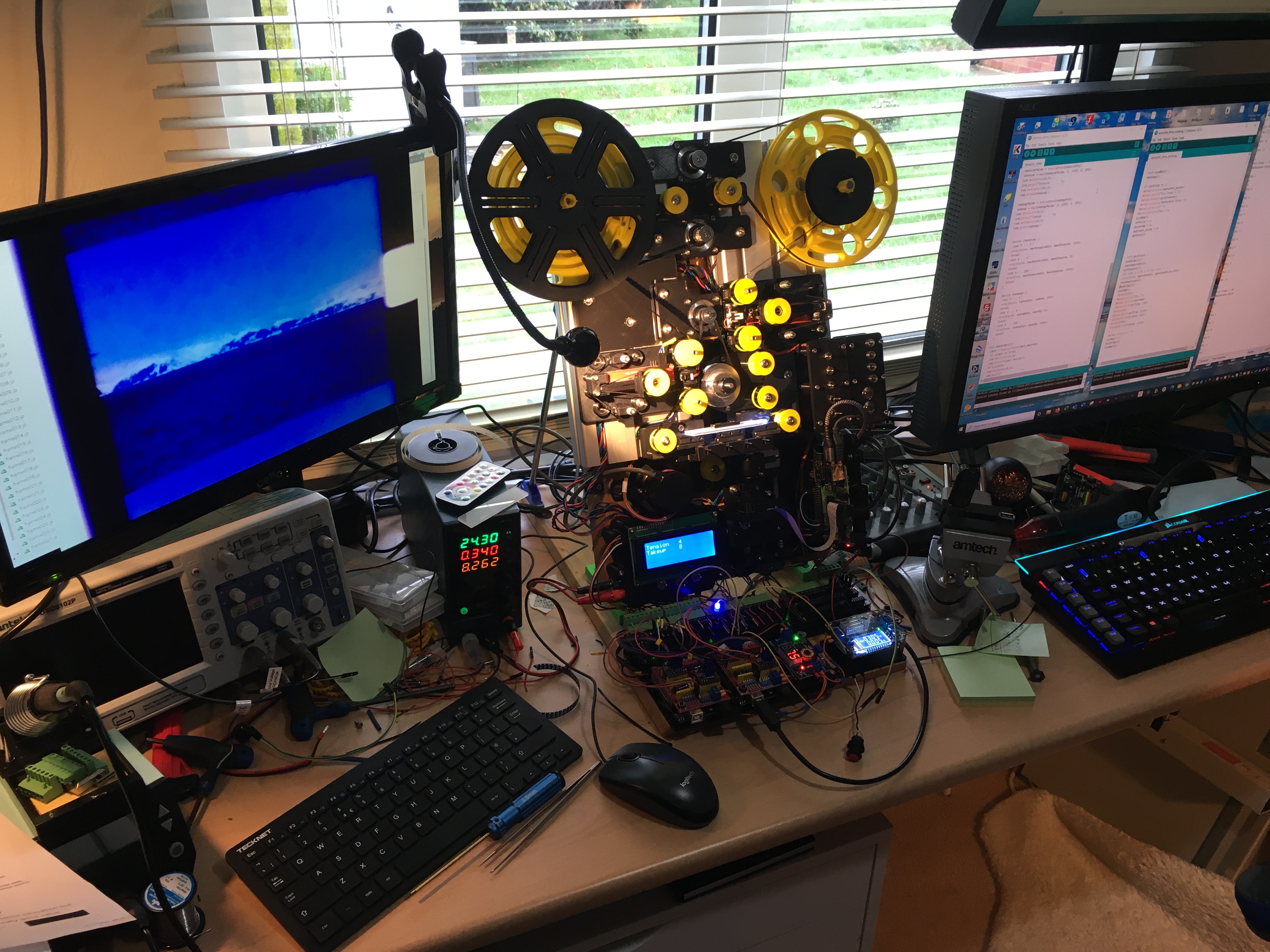
So after 2 years thinking about this project I finally have a working system. It probably is a bit over the top but I wanted to explore a few ideas to the thing has evolved.
The scanner uses independent stepper motors for feed and takeup. A spring loaded system provides feedback for the motors and maintains a constant film tension no matter what size spool is used. The actual tension is adjustable. A third stepper drives a sprocket wheel recovered from an old viewer, this is also connected to an optical rotary encoder used to provide a timing pulse for each full rotation.
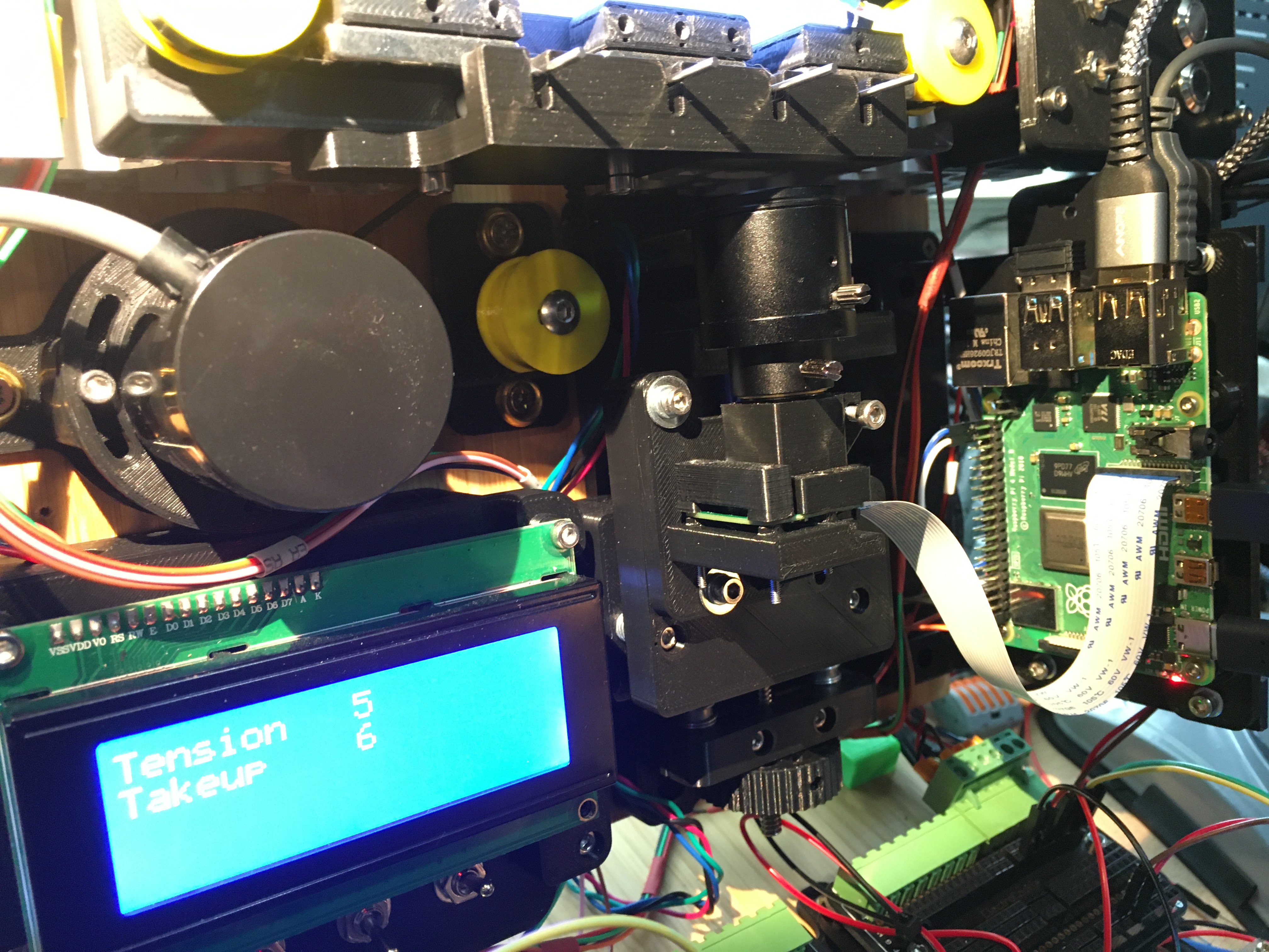
The takeup and back tensions are controlled by an arduino uno. A second uno handles the sprocket wheel timing. I could have used a single uno but having two enables me to isolate the two drive systems an simplify matters. Camera is a PiV2 mounted on a motorised focus rail and spring loaded mount to enable alignment. Light source is a led flat panel and exposure controlled by varying the drive voltage (poor colour temperature but this can be corrected). Images are collected with a Pi4, stored to usb stick for transfer to the pc. I use Adobe Premiere to edit and the built in stabilisation function to remove frame movement.
Sprocket drive. I had to change the film path so this is not great but works ok. Film wraps round sprocket and locates in 7 sprocket holes. This should even out any film with worn holes.
Rotary encoder on left, this is on an adjustable mount so the relative position of the pulse can be adjusted to put the frame in the right place. Will explain later.
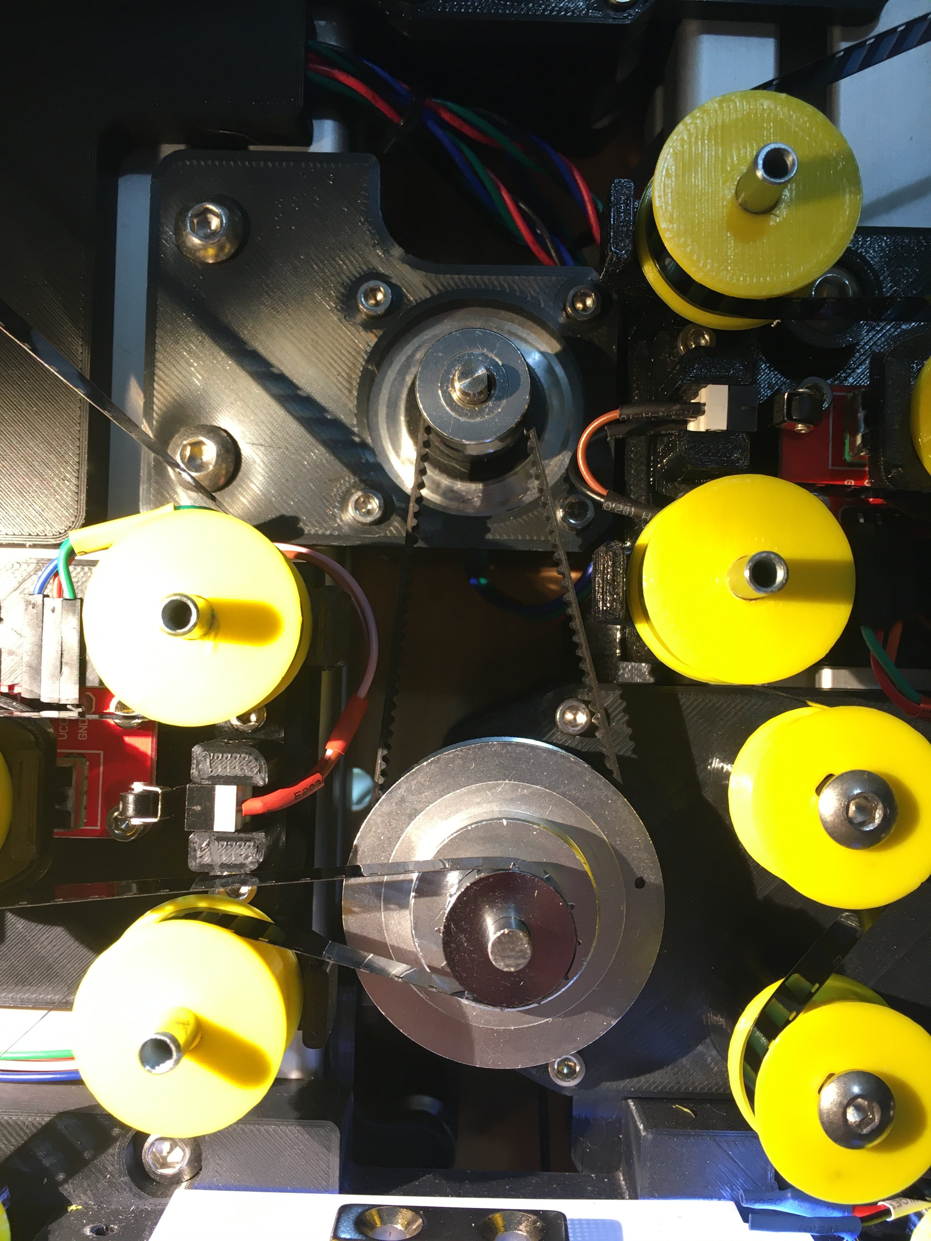
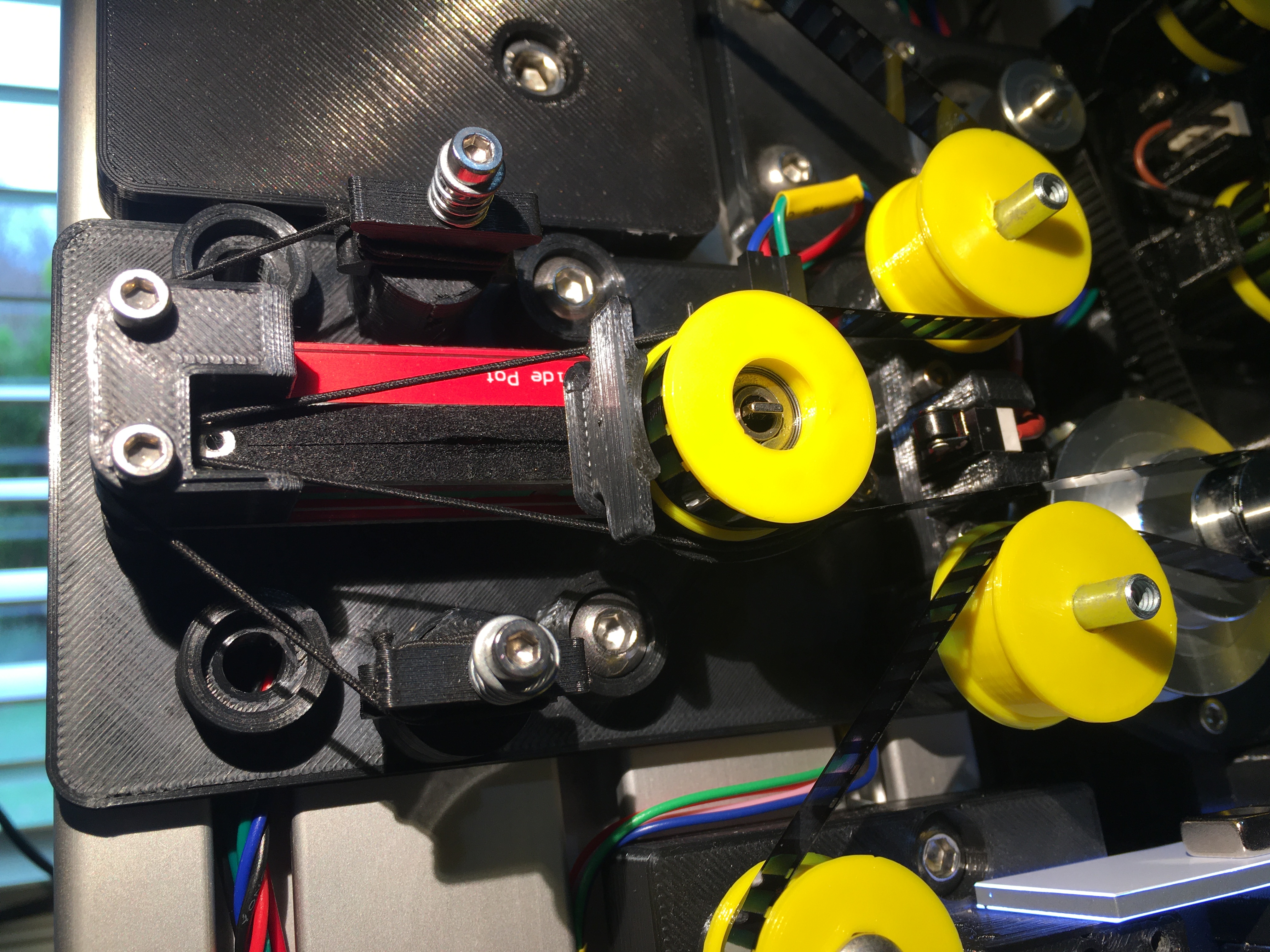
Tension system. Main part is a slider pot as found on mixer desks. Bungee cord pulls film to left, pot resistance provides feedback so motor turns to compensate by tightening film and pulling to the left. Feedback has a null range to provide hysterisis and prevent oscillation. Actual tension is controlled by adjusting cord length. Limit switch stops motors.
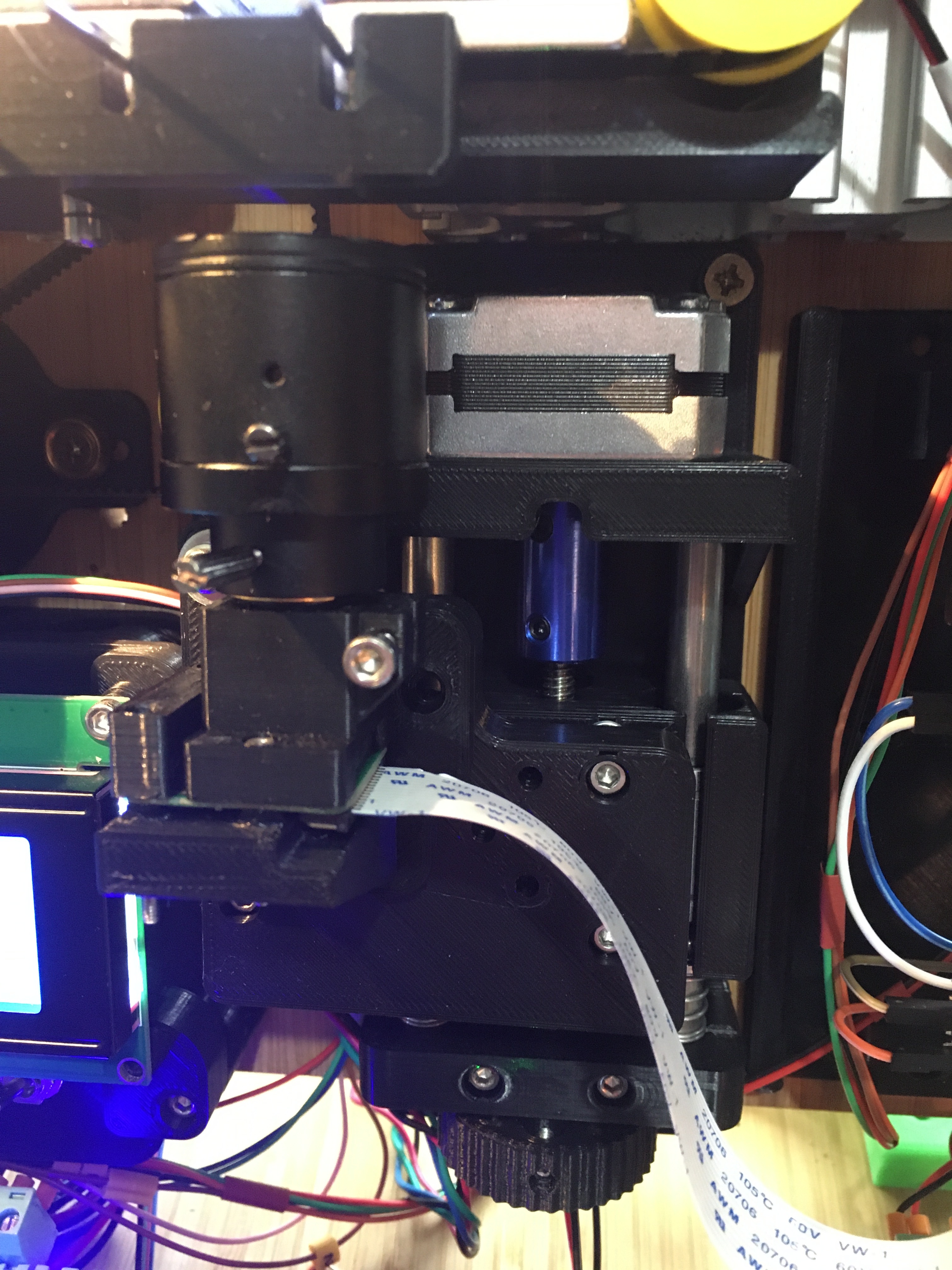
Camera and focus rail
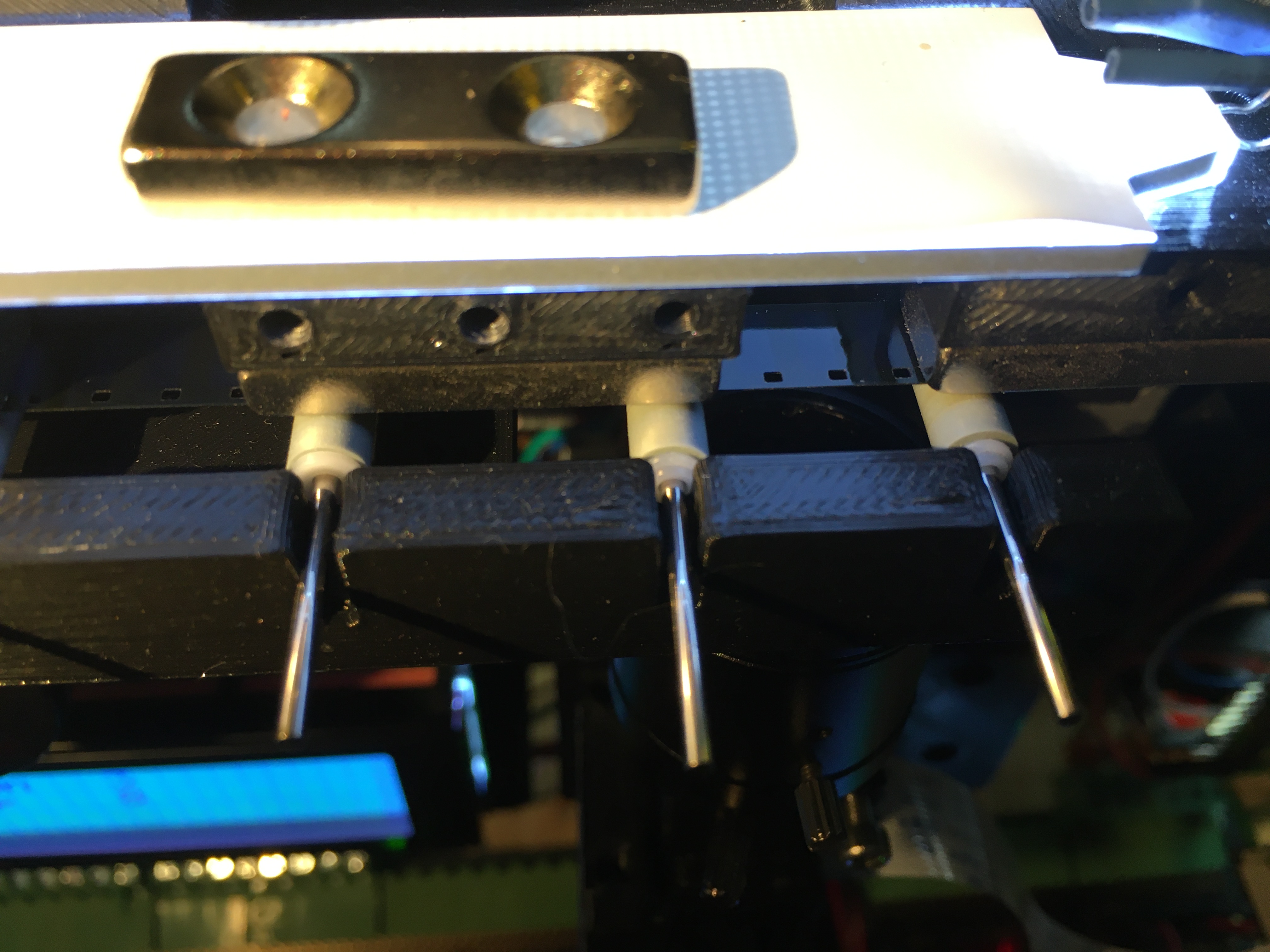
Film gate. Film runs on neodynimum magnets - very smooth surface so no change of scratching film. Film held flat on gate using magnetic rollers. These are plastic rollers recovered from a printer. The center pin is held by the magnets and the roller rotates as the film moves underneath. Discovered by accident but works a treat, again no possibility of scratching the film. This may be of interest…
Enough for now, I just wanted to get the ball rolling. Bottom line is that it works ok but image quality below par so have to look at alternatives.
5 Likes
For info this is how I use the encoder system.
This is a true 600ppr optical encoder with AB & Z outputs from Bourns, available on ebay for around £20. Rated for several thousand rpm so should last forever. Wide operating voltage, open collector output.
Sprocket drive stepper uses 9600 steps for 1 revolution.
Sprocket wheel has 12 sprockets so needs 800 steps per frame.
Taking an image every 800 steps does not work as there is no guarantee of hitting the reference pulse each time.
Wait for ref pulse, take image.
Send 800 pulses, take image
repeat 11 times
Wait for reference pulse, take image.
If the number of steps between image 11 and the next reference pulse is not 800 it will only be a few out and not make any real difference. The whole sequence is reset every full revolution and provides a well registered image.
My sprocket system would benefit from being much closer to the film gate but had to start somewhere.
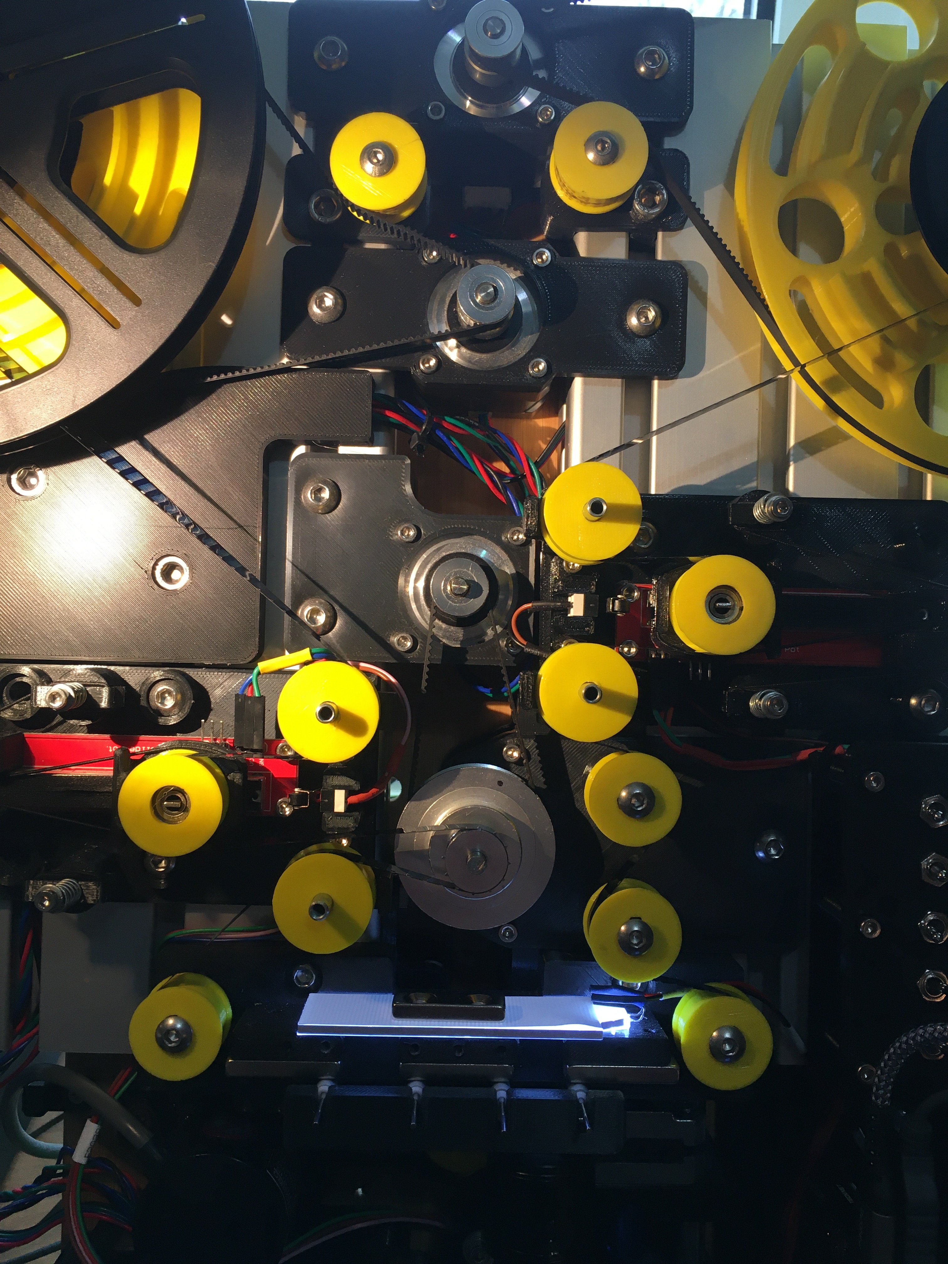
Hi. Love the machine. Can I ask why you have so many rollers? Is it for tension? Also if they are 3D printed could you please share the STL?
I’m sketching up a project I’ve had in my head for a while. It only has four rollers and two stepper motors. I was going to mount them on maker beams. From your experience am I oversimplifying the machine?
Thanks.
Each tension system needs 3 rollers to form a loop.
The two rollers just below the right tensioner were used to form the loop around the sprocket.
The rollers at each end of the film gate ensure the film path is flat.
So every roller has a purpose and I can’t simplify it. I would attach extra leader to a film if it is too short to run the full length before scanning. I did change the sprocket drive from the right which relied on the takeup tension to the left so it pulls the film over the gate. This improved registration.
The film gate is quite long as I originally intended to use an additional camera (MVcam) to locate the sprocket holes using machine vision, potentially good but requires a bit more programming knowledge than I have. Maybe another day. If I make a MK2 then the sprocket would be as close to the film gate as possible.
Apart from the obvious, the whole system has been 3D printed which allows me to change designs when needed. Having a printer (or 2) opens up a whole world of possibilities without relying on the constraints of pre manufactured items. I used the aluminium extrusion as it allowed positioning and mounting options and the two boards are from Ikea…
The rollers are either plain with 5mm clearance hole or incorporate a 5mm bearing. I will post both for you.
Thank you. I started a project last year and got a bit overwhelmed and shelved it. I’m looking to get it going again.
I have a Anycubic I3 Mega 3D printer which as you say is great for things like this 
Love the slide pots as a tension feedback system. Very clever!