As a follow-up on a recent exchange of ideas, I tried to transplant one of the brains of my scanner. Specifically, I looked into the possibily of replacing the original Arduino, programmed in C++ with a Raspberry Pi Pico programmed in Micropython. In summary: its possible, but it was non-trivial.
Before going into the details, here’s a short overview of my scanner.
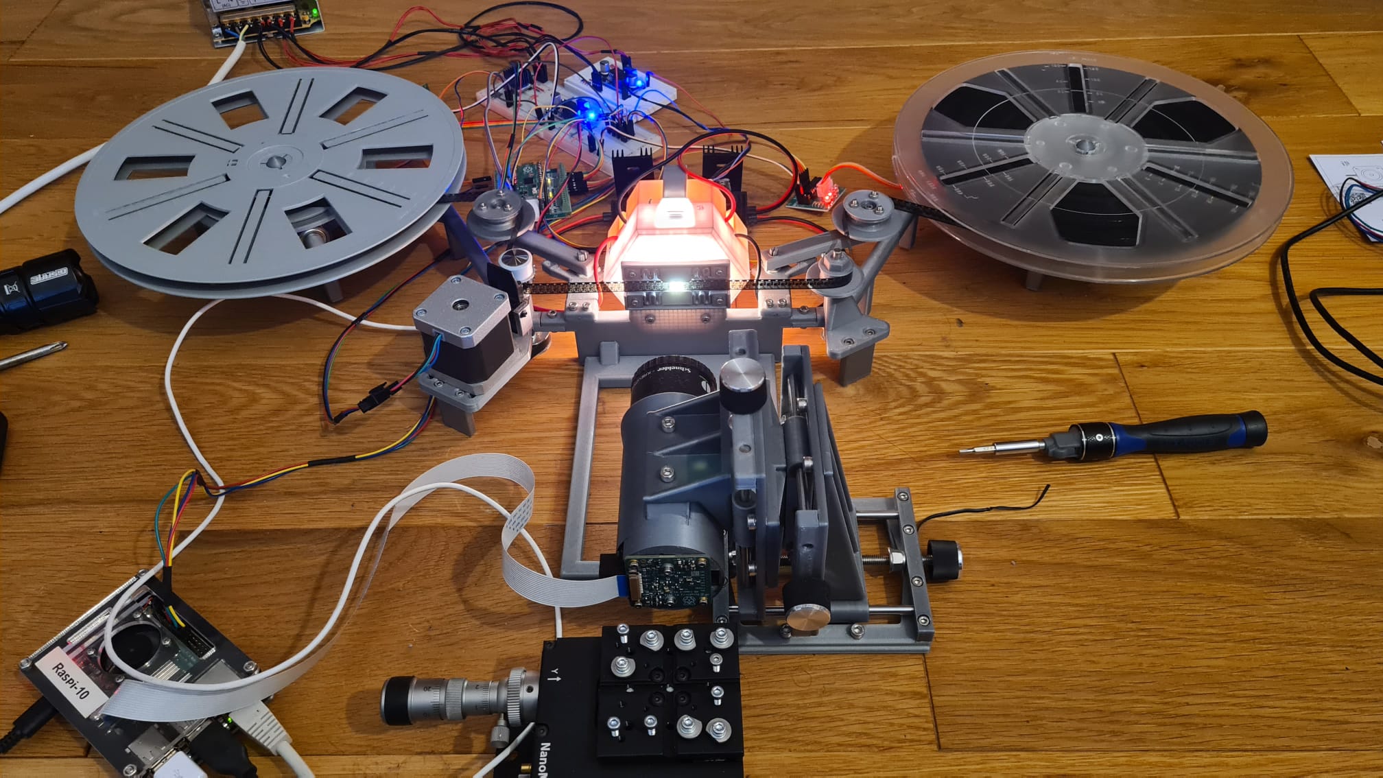
While I initially thought this setup was a cool idea, it turned out to be anything but practical. For starters: never use plastic parts in a Super-8 scanner. The flexibilitiy of plastic material leads to all sorts of alignment problems - even a few microns movement of the film or camera results in noticable pixel shifts in the image with these formats. Plastic is just too flexible for these tasks.
Anyway. There are a total of three stepper motors in this setup. The main filmstepper is the rather large unit slightly left of the camera. The two other steppers are the smallest and cheapest geared stepper motors I could find, namely the 28BYJ-48 brand of steppers. These two are located below the takeup and supply spools.
The filmstepper has a quite simple task. Most of the time it is stationary and holds its position. For every capture, it is commanded by the RP4 (visible above in the left lower corner) to advance for varying distances, depending on the current sprocket position. As this stepper is a 0.9° one (that is: it needs 400 steps per revolution) and the driver chip uses 16 microsteps, a full frame advance takes exactly 800 steps (some gears involved).
I wanted the movement of the film to be fast, but not too fast in order to handle the film decently. Specifically, I wanted a single frame advance to happen within 0.2 sec - not faster. Doing the math, you arrive than at required driving frequency for this stepper at about 4kHz. Now, that is a problem with the Pico running Micropython. The fastest time a timer can be called in Micropython is 1kHz. So you have two choices - program the Pico in C++, or open up the box of Pandora. Of course, I opted for the later.
The Pico features some neat additional hardware to come to the rescue. Specifically PIOs (programmable I/O state machines) and DMA channels running indepently of the CPU(s). However, programming these units in Micropython is not easy; especially setting up the DMA controllers is not yet supported in my Micropython versions (it will however be supported shortly in a new release of Micropython).
So I ended up with writing directly into hardware registers of the Pico to set DAM things up - reminded my strongly of the old “peek” and “pook” area (80s of the last century). Once the DMA-extension of Micropython for the Pico is available, I will need to update my code.
Anyway. I succeed in chaining three DMA-channels sending precomputed data into a PIO-program which outputs step and direction signals to the driver board. The timing of these pulses is very precise, because there is no CPU involved in this. Only DMA channels and a PIO - both are independent of the CPU and have their own memory interfaces.
The CPU is used in the initialization phase to compute an acceleration/deceleration ramp. These ramps have a total size of 150 steps to slowly start and stop the stepper motor before running at full speed.This is important in two ways: First, the film is not subjected to a sudden large force, but actually only to a smaller, constant force. Secondly, the stepper also starts slowly so that no steps are lost. The later might happen if the stepper is starting with the highest velocity.
The CPU also handles the setup of the DMA channels for each single movement. If for example, the RP4 has requested a movement of 796 steps, it will setup DMA channel 1 for the initial acceleration ramp of 150 steps and DMA channel 3 for the final 150 deceleration steps. DMA channel 2 will be the high speed part, setup to do 631 steps. Finally, the CPU will trigger DMA 1 which, once finished, will trigger DMA 2 which in turn will trigger DMA 3. This DMA 1 → DMA 2 → DMA 3 process will run totally independent of the CPU, finishing the requested move in about 0.2 secs.
The whole timing of the process is done by the PIOs statemachine running at a fixed frequency – in my case 2MHz. I have tested this setup with up to 16 Mhz driving frequency. But a full frame advance in less than 0.02 sec is too fast for my taste.
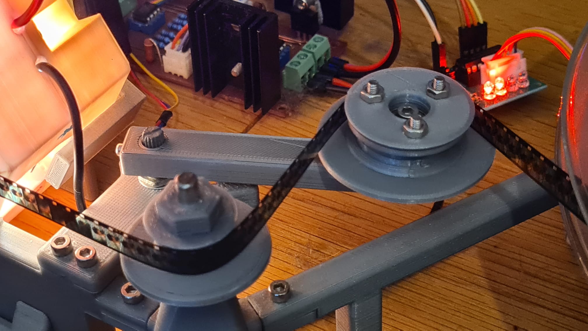
The two other steppers are a quite different. These two steppers drive directly the supply and takeup spools. Here, angular resolution is important. Especially if the spool is full, like on the right side of the above image. Even a single step can result in a large change of tension. This is less critical if the spool is nearly empty (left side of the image above).
The tiny steppers I am using have an angular resolution (in half-stepping mode) of 0.09°, that is, a factor of 10 better than the big film stepper (which is already a factor of two finer than usual steppers).
These steppers are run in a kind of “jog” mode. On each side of the film gate, there are two tension measuring devices. These are basically a movable arm attached to 5k-potentiometers.
In retrospect, using potentiometers as sensors was a bad decision. They simply wear out to fast and than create quite noisy signals.
The Pico’s ADCs measure the voltage and calculate a tension values from these. A simple proportional error signal is derived from the difference between measured and desired tension, and is fed into the stepper units every 0.03 sec. If the tension is at the desired value, nothin happens. Deviation start to turn the stepper into the appropriate direction to achieve again the desired tension value. The larger the deviation, the faster the steppers move. That is the “jog” mode I mentioned above.
The tension steppers are rather slow steppers. In order to be sure that no steps are missed, one should leave at least about 2 ms time between each step. That opens up the possibility to handle these two motors with the Timer units Micropython is supplying (the fastes they can run is at 1 ms). And indeed, this is the implemenation I opted for. Here’s that simple code:
from machine import Pin, ADC, Timer

class TensionStepper(object):

    def __init__(self,pinNo=10,msTime=1):

        self.pins = [Pin(pinNo  , Pin.OUT),
                     Pin(pinNo+1, Pin.OUT),
                     Pin(pinNo+2, Pin.OUT),
                     Pin(pinNo+3, Pin.OUT)]

        self.sequenceH = [[1, 0, 0, 0],
                          [1, 1, 0, 0],
                          [0, 1, 0, 0],
                          [0, 1, 1, 0],
                          [0, 0, 1, 0],
                          [0, 0, 1, 1],
                          [0, 0, 0, 1],
                          [1, 0, 0, 1]]

        self.sequenceF = [[1, 0, 0, 0],
                          [0, 1, 0, 0],
                          [0, 0, 1, 0],
                          [0, 0, 0, 1]]

        self.sequenceS = [[1, 1, 0, 0],
                          [0, 1, 1, 0],
                          [0, 0, 1, 1],
                          [1, 0, 0, 1]]

        self.sequence = self.sequenceH

        self.phase     = 0
        self.steps     = 0
        self.direction = 1

        self.hold      = False

        self.driver    = Timer(mode=Timer.PERIODIC,period=msTime,callback=self.doStep)

    def doStep(self,dummy):

        if self.steps!=0 and not self.hold :

            self.phase += self.direction

            if self.phase>=len(self.sequence):
                self.phase = 0

            if self.phase<0 :
                self.phase = len(self.sequence)-1

            for pin in range(len(self.pins)):
                self.pins[pin].value(self.sequence[self.phase][pin])

            self.steps += self.direction

    def move(self,amount):

        self.direction = 0
        self.steps     = amount

        if amount>0:
            self.direction = -1
        else:
            self.direction = +1

    def setSequence(self,sequence=0):

        self.hold = True

        if   sequence==0:
            self.sequence = self.sequenceH
        elif sequence==1:
            self.sequence = self.sequenceF
        elif sequence==2:
            self.sequence = self.sequenceS

        self.hold = False

    def pause(self):
        self.hold = True

    def cont(self):
        self.hold = False
The original Arduino implementation was much more complex and harder to understand. So here Micropython really shines.
Paired with each driver is another timer-driven unit for reading the ADC values, averaging them over a fixed time interval and outputing the required step signal to the TensionStepper units. This was necessary because of two design flaws. One being my wiring done on a breadboard, the other the less than optimal ADC performance of the PICO. Specifically, the switching power unit on the Pico creates noise on the ADC reference voltage, spoiling the fun of having 10bit ADCs on the Pico. One way to improve that is to use the following code
# This sets the Pico to high power mode, reducing ADC noise
highPower = Pin(23, Pin.OUT)
highPower.value(1)
which switches the power unit to a different mode, drawing more current, but operating quieter.
Speaking of current – the Pico + some other peripherals are powered through the RP4, connected via a USB-cable. This cable is also used for two-way communication between the RP4 and the Pico. This took a while to set up. In fact, it was here that I discovered that Micropython has still some deficits. I first tried to use the REPL mechanism of the Pico via the USB-cable; I was unable to achieve good results here - too much delay, and some byte values do reset or interrupt the Pico. Then I looked into connecting the Pico as I2C slave to the Raspberry Pi - would have been a nice and fast way to communicate. Turns out that there is not “slave” mode implementation of I2C in the Pico’s Micropython version. Dead end. It would be possible in Circuitpython or in plain C++ - but than, the whole code would have to be rewriten. In the end, just opening the appropriate serial device on the RP4 and using a polling code on the Pico side like so:
import select
import sys

# setup poll to read USB port
poll_object = select.poll()
poll_object.register(sys.stdin,1)


buf = "Enter your keys ('q' aborts)"
print('%s'%buf)
buf = ""
while True:

    # check usb input
    if poll_object.poll(0):

       #read as character
       ch = sys.stdin.read(1)
       buf += ch

       if ord(ch)==0x0A:
           if len(buf)>1:

                print('\n buf: %s'%buf)

                if ord(buf[0])==ord('q'):
                    print('Bye!')
                    sys.stdin.close()
                    print(sys.version)
                    sys.exit(0)
           buf = ""
did the trick. Just send some stuff through the RP4 serial to see the Pico respond.
As the above code shows, output data via USB-serial can be simply done like so:
print('\n buf: %s'%buf)
So… – in summary, driving various breeds of stepper motors with a Pico and Micropython can be done, by various means. The Pico-specific Micropython implementation lacks some important features and progress is slowly. Much better software support can be found by using C++ as programming language (it works also in the Ardunio IDE) - but even for me as an old C/C++ programmer, Micropython is much more fun.