Wanted to share my RobinoScan Strobe system. Hopefully it helps some of you and hopefully we can improve it with the community.
It works using an Arduino Mega and the flashes are triggered very precisely to each exposure. There are things to improve but this currently works 100% on RobinoScan.
If anyone builds it or improve on it please share your findings. The next step is overdriving the LEDs to get more light output. When strobing we can overdrive the LEDs because they are not constantly turned on.
QUICK GENERAL INSTRUCTIONS: (this is using a Flir Oryx 5.3K camera but it should work for any Genicam compliant cameras - you will need to tweak this to your needs…)
..in SpinView
- Set your camera Trigger mode to “ON”.
- Connect your scanner’s trigger to an input line (for me I use TTL line 2)
- Via DIGITAL I/O - Set an output line (for sending signal to the Arduino and trigger a Flash)
Set the “line source” to your input line (in my case it’s TTL line 2)
Note that for 35mm you have to set a counter to receive 4 triggers and then trigger the line out for your flash… it’s all in the Genicam software and you can figure that out by experimenting. OR if your trigger is via a microcontroller you can do the counting there as well.
- Set a Trigger Delay (from the Acquisition Control menu) if needed to better line-up your flashes pulses to your exposures.
- I saved User settings for 16mm and 35mm since they use different counters.
Here’s a diagram to help visualize:
robinoscanLED.pdf (435.2 KB)
Here’s the 3D model (.STEP) of the Integrating Sphere with heatsink mount.
SHOPPING LIST:
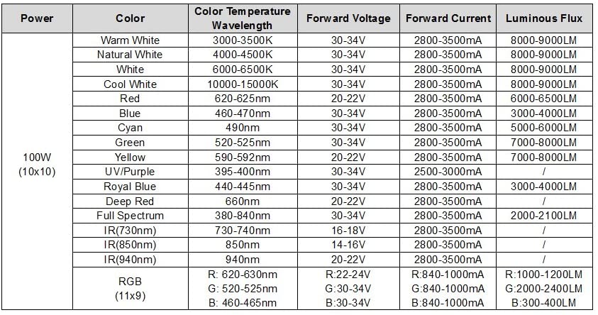
100W RGB LED CHIP:
ARDUINO MEGA:
DC2197A-A DAC
https://www.digikey.com/en/products/detail/analog-devices-inc/DC2197A-A/5011089
or
PICOBUCK:
or
HEATSKINK: (you can ditch the plastic lens or make yourself a “monocle”)
PSU: (at your discretion but at least 36V 3A)
ARDUINO MEGA CODE (small thing to improve in code would be to setup an interrupt for the sensor BUT I can guarantee that it doesn’t skip a beat the way it is..)
#define PWM_PERIOD  1599    //#     PWM freq = 1/((K+1)*62.5E-09)
#define HIGH_DUTY1  1595    //# BLUE     DC = K/PWM_PERIOD   <-- channel 1
#define HIGH_DUTY2  1595  //# GREEN    DC = K/PWM_PERIOD   <-- channel 2
#define HIGH_DUTY3  1250  //# RED    DC = K/PWM_PERIOD   <-- channel 3
#define LOW_DUTY    0     //#     DC = K/PWM_PERIOD
#define PULSE_LEN   1000ul  //uS    length of high-duty PWM pulse

const uint8_t pinSensor = 10;    //sensor input
//
const uint8_t pinPWM1 = 5;      //OC3A BLUE
const uint8_t pinPWM2 = 2;      //OC3B GREEN
const uint8_t pinPWM3 = 3;      //OC3C RED
//
const uint8_t pinDbg = 6;       //debug

uint8_t
    nowSensor,
    lastSensor;

uint32_t
    tNow,
    tBlip;

void setup()
{
    //set up timer 3 to use OCA, B and C
    //  WGM14 TOP is ICRx -> 1599 gives 10kHz
    //  prescaler == /1
    //  for WGM14, COMxA..C1:COMxA..C0 == 10 OCxA..C sets on BOTTOM, clears on COMPARE
    TCCR3A = _BV(COM3A1) | _BV(COM3B1) | _BV(COM3C1) | _BV(WGM31);
    TCCR3B = _BV(WGM33) | _BV(WGM32) | _BV(CS30);
    ICR3 = PWM_PERIOD;
    OCR3A = LOW_DUTY;
    OCR3B = LOW_DUTY;
    OCR3C = LOW_DUTY;
    //
        pinMode(pinSensor , INPUT_PULLUP);
    pinMode( pinPWM1, OUTPUT);
    pinMode( pinPWM2, OUTPUT);
    pinMode( pinPWM3, OUTPUT);

    pinMode( pinDbg, OUTPUT );


}//setup

void loop()
{
  static bool
        bFlag = false;

    switch( bFlag )
    {
        case    false:
            //look for sensor input to transition low to high
            nowSensor = digitalRead( pinSensor );
            if( nowSensor != lastSensor )
            {
                lastSensor = nowSensor;
                if( nowSensor == HIGH )
                {
                    //transitions seen
                    //set OC to high-duty
                    OCR3A = HIGH_DUTY1;
                    OCR3B = HIGH_DUTY2;
                    OCR3C = HIGH_DUTY3;
                    //save the micros count when we went high
                    tBlip = micros();
                    //and move to time the period
                    bFlag = true;
                    //for debugging/scoping
                    digitalWrite( pinDbg, HIGH );

                }//if

            }//if

        break;

        case    true:
            //when blip done...
            if( (micros() - tBlip) >= PULSE_LEN )
            {
                //go back to low duty cycle
                OCR3A = LOW_DUTY;
                OCR3B = LOW_DUTY;
                OCR3C = LOW_DUTY;
                //go back to look for next low-transition on sensor input
                bFlag = false;
                //for scoping
                digitalWrite( pinDbg, LOW );

            }//if

        break;

    }//switch

}//loop
Happy flashing!
ps:. I’m sending my camera back to FLIR for a repair tomorrow- so during the 2 weeks downtime I will be working on a new system, trying to overdrive the LEDs.