Craft flocking! I love it. Great hack.
Well, it kind of worked. It’s a definite improvement, but not perfect. Still seeing some reflection even off the velvet, so I think we’re going to need to install a bellows between the camera and lens.
BTW, the scanstation uses the same sort of thing inside the camera assembly, butI think it works better because the relative size of the assembly is larger than ours, so any reflections are out of view of the camera.
I also used this stuff inside a telescope I built about 25 years ago. Great stuff, and cheap.
1 Like
From a word I didn’t know existed to a whole world I didn’t know existed:
http://www.CraftFlocking.com
haha. that’s a little different than what we’re using. You can get sheets of self-adhesive flocking from amazon, which is all I got.
To make it easier to install in the box I got sheets that were a manageable size (Rather than a long roll), and cut it to the right width to fit the walls, then carefully stuck it to the inside of the walls. It comes off fairly easily too- the adhesive isn’t super permanent. It’s used a lot for things like lining a box to display jewelry.
We’ve had nothing but trouble with the LED drivers we have tried to have people design for us. And the cheap Sparkfun Femtobuck has been incredibly reliable so far. Now that we have the DAC circuit nailed down and working well with the femtobuck, the decision was made to simply use it in the final design. At least, for this iteration.
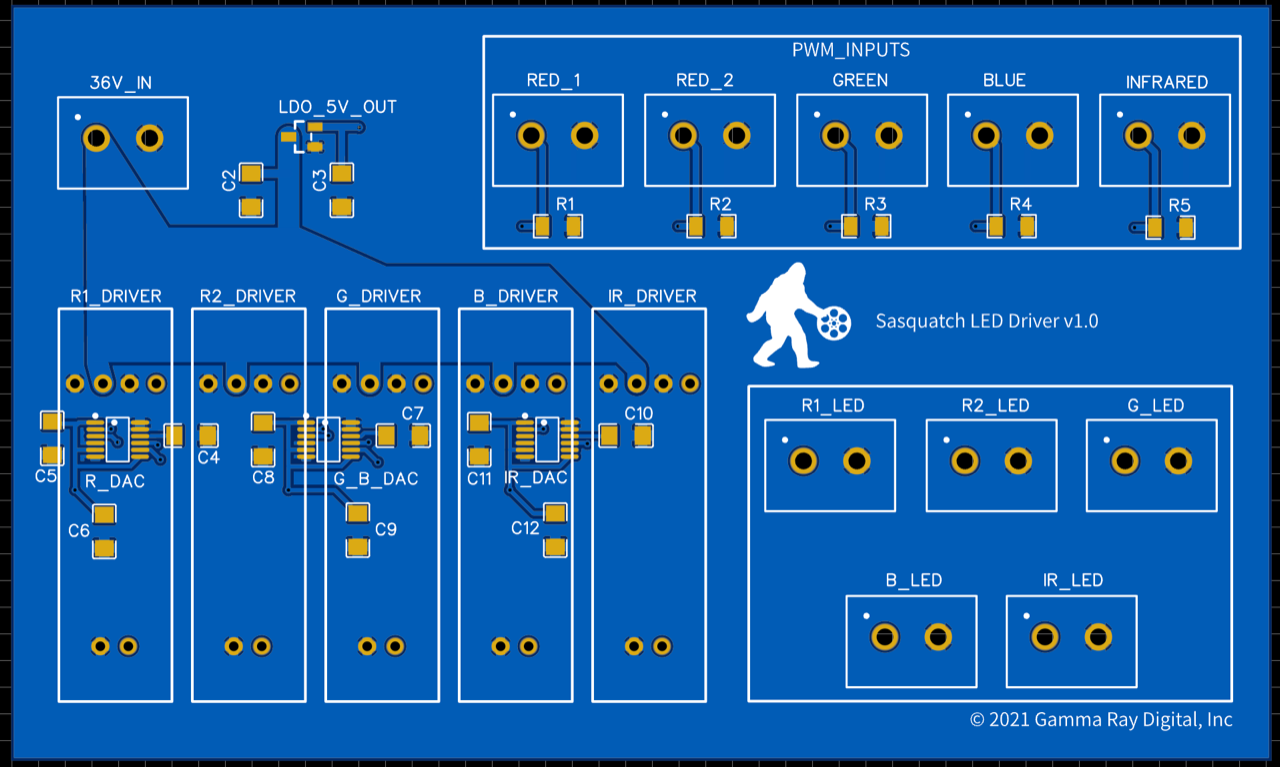
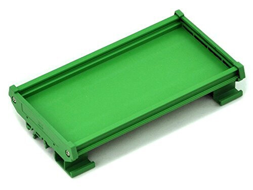
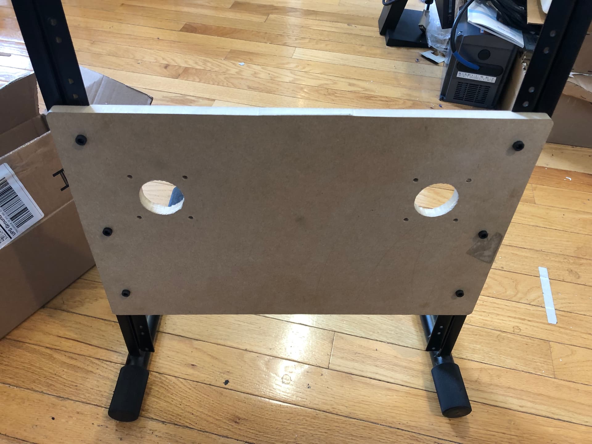
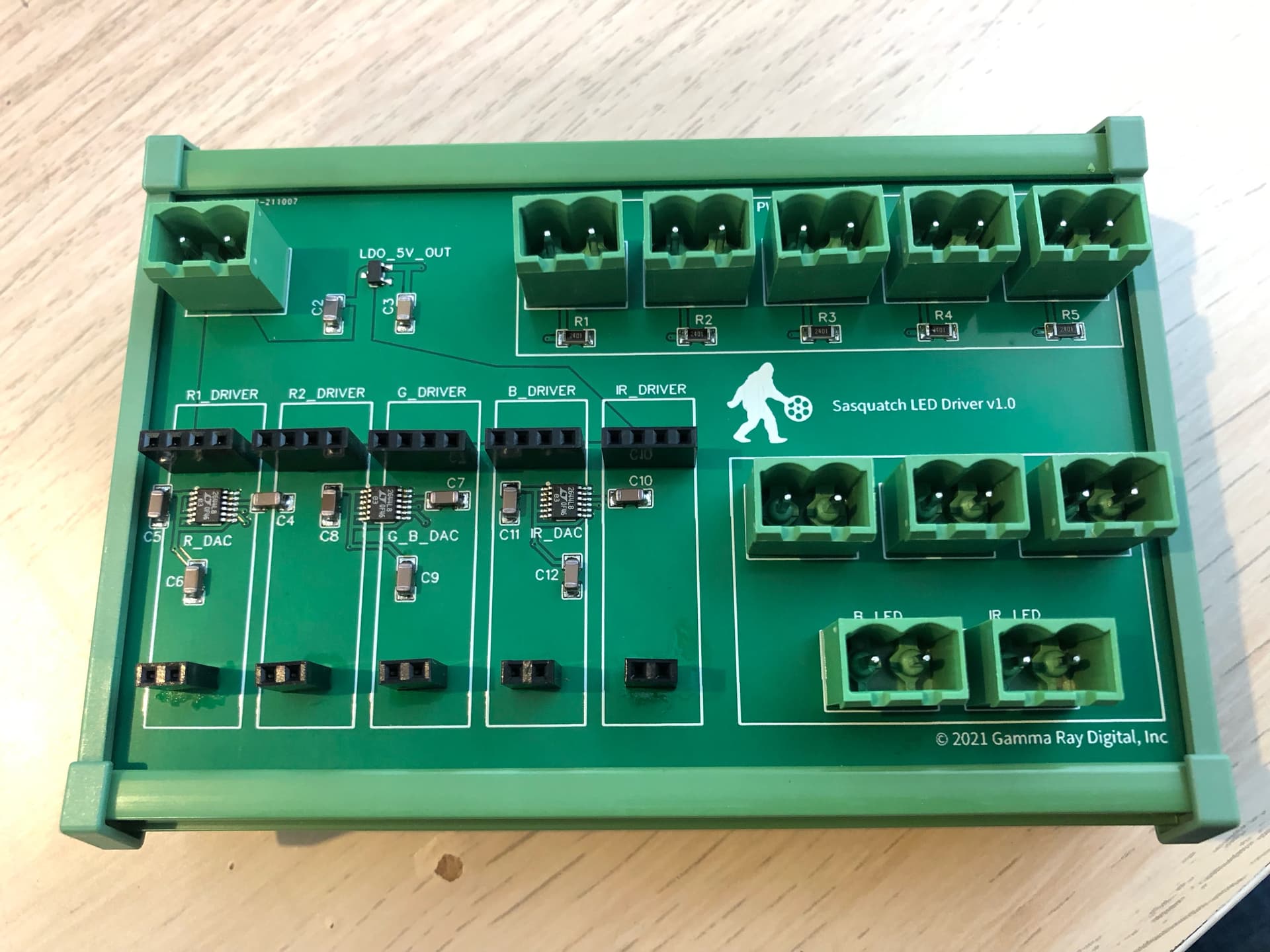
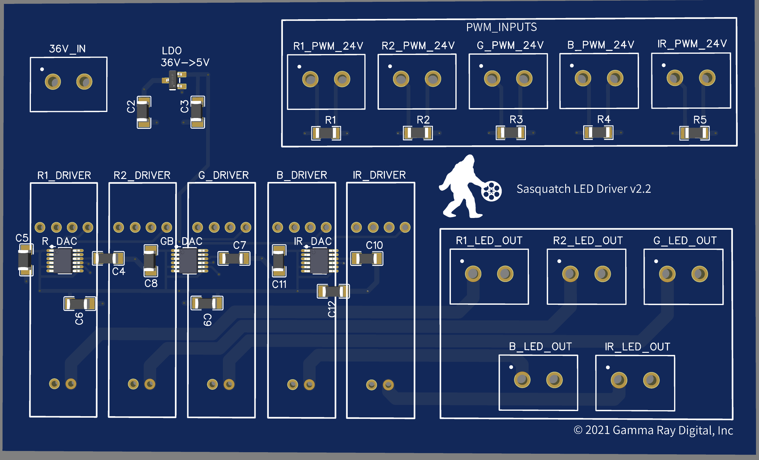
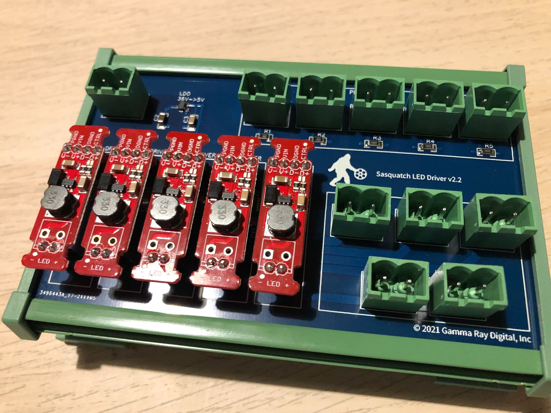
So this is the driver board design. It’s 120x72mm and fits inside one of these, on a DIN Rail:
Basically what we’re doing here is taking 36V in from the power supply, feeding that to a bank of 5 Femtobuck drivers (which instead of having screw terminals soldered to them, will get pins that fit into header sockets on the board). The DACs convert PWM to an analog voltage, which goes out to the Femtobuck driver, eliminating lines in the image when dimmed.
If the AL8805 chip used in the Femtobuck is ever back in stock anywhere, we could also make a single daughter card that contains the 5 drivers and matching sockets to plug into this. But for now, at $7 each, it’s kind of a no brainer to just use the pre-assembled Femtobucks in this way.
Underneath the drivers is where you see the DAC circuits - three of them. Each chip supports two signals, and we need 5. the PWM input from the ClearCore is at 24V, which is too high for the DACs, so the resistors below those complete a voltage divider (half of which is in the clearcore in the form of a 10kΩ resistor), dropping the PWM voltage below 5.5V, which is what the DAC wants.
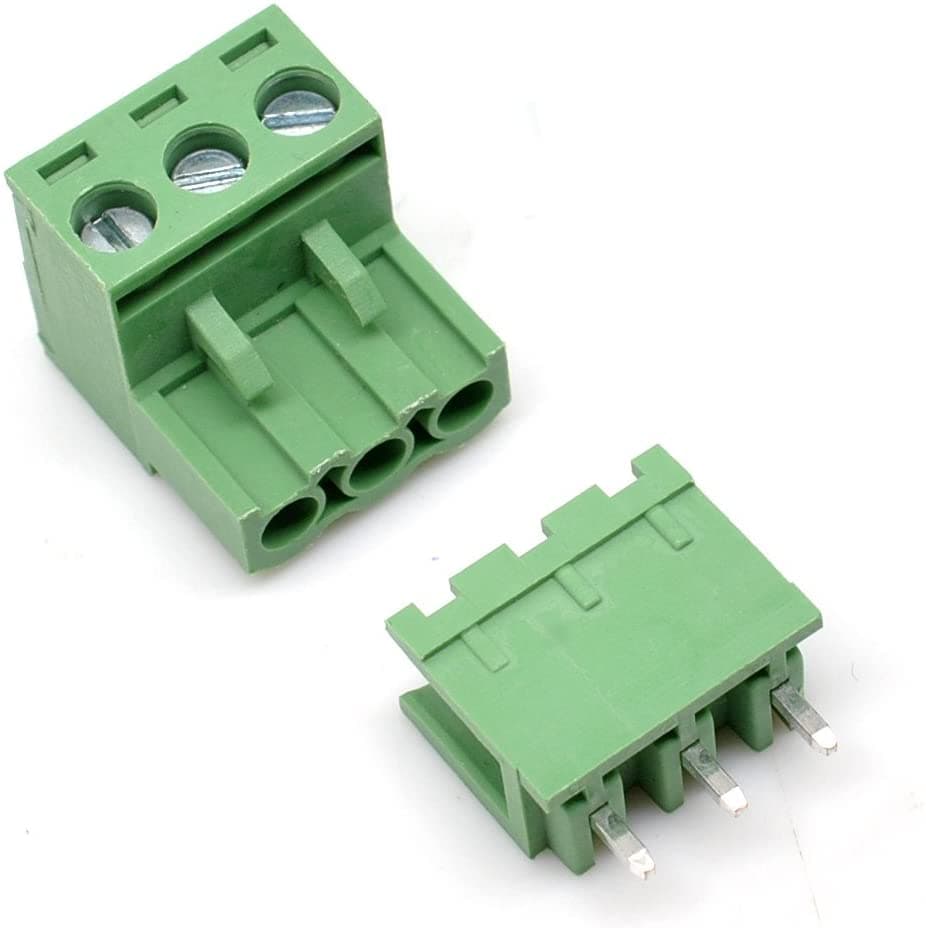
All of the connectors are Euro-style 2-position screw terminals, which makes it easier to tweak things while we’re still working on it. Sort of like these:
Should have this in hand in about a week.
1 Like
Nice layout, suggest you may need some noise mitigation, but I am not familiar with the femtobuck.
Question, what part are you using as the LDO to 5V? I am looking for an option with high absolute voltage. Thanks
Thanks. We’ve been using this setup on a breadboard for a couple weeks and if anything is going to be noisy, that’s going to be it, with so many wires going all over the place. Everything has worked as expected.
The LDO is this one, from Microchip. 55V max Vin.
Agree.
Thanks for the LDO specs.
Some fun stuff happening here today.
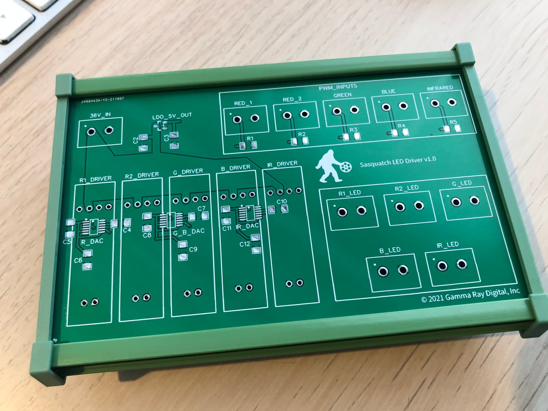
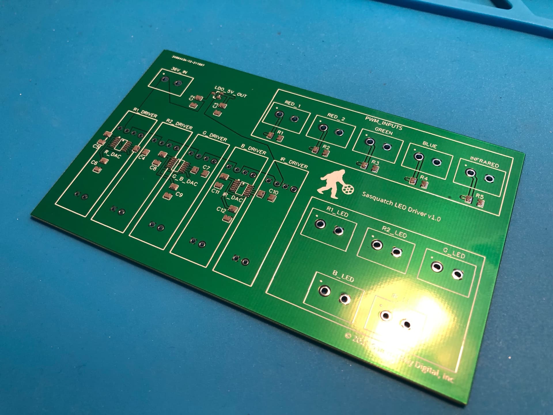
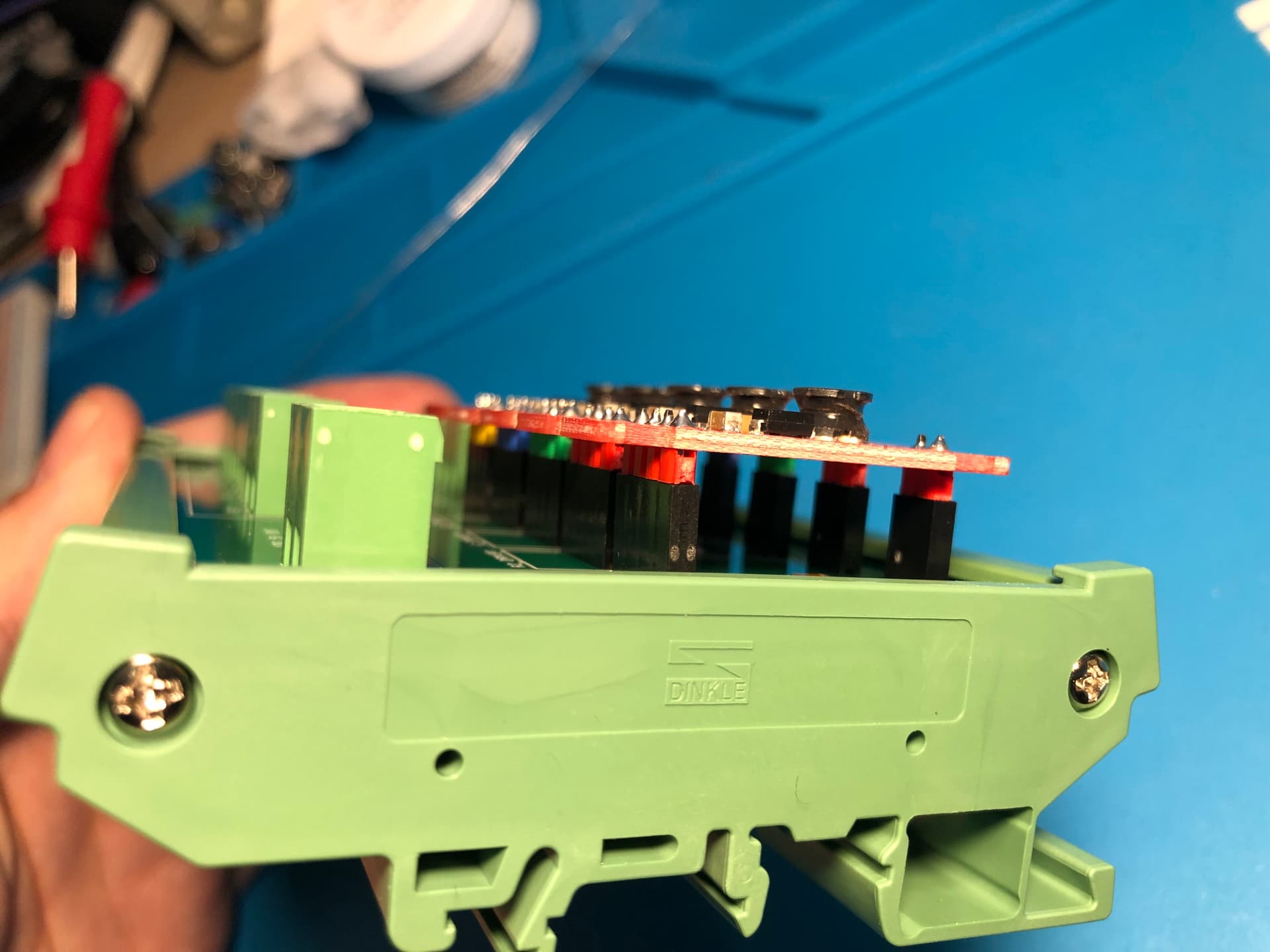
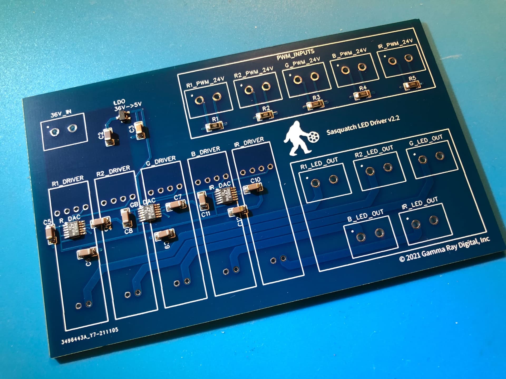
The PCB for the driver finally cleared customs and arrived this morning. Fits perfectly in the 120x72mm DIN rail mount:
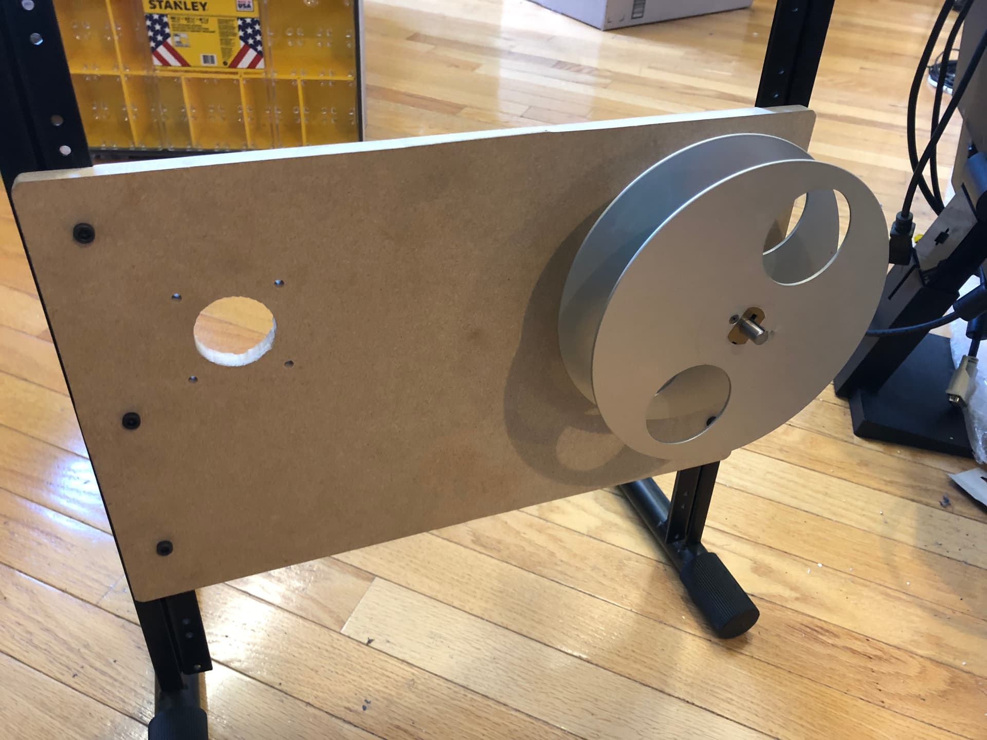
And our firmware developer wanted to test the motor tension functionality from his home setup rather than having to come in here. We got another motor for him to use and yesterday I ran this on the CNC router downstairs:

I bought some 5/16" keyed shaft stock, and this will hold a couple tiny (400’) split reels. Waiting on some 10mm->8mm couplers to arrive this afternoon then we can assemble the whole thing. I’ll post more when these are all put together later in the day.
1 Like
Chasing down other things today so I haven’t had time to actually test it but:
Got one of the motors installed in the test deck:
Using a solder stencil and reflow oven is the only way to deal with SMD components. Here’s the board being held in place by some other scrap boards:
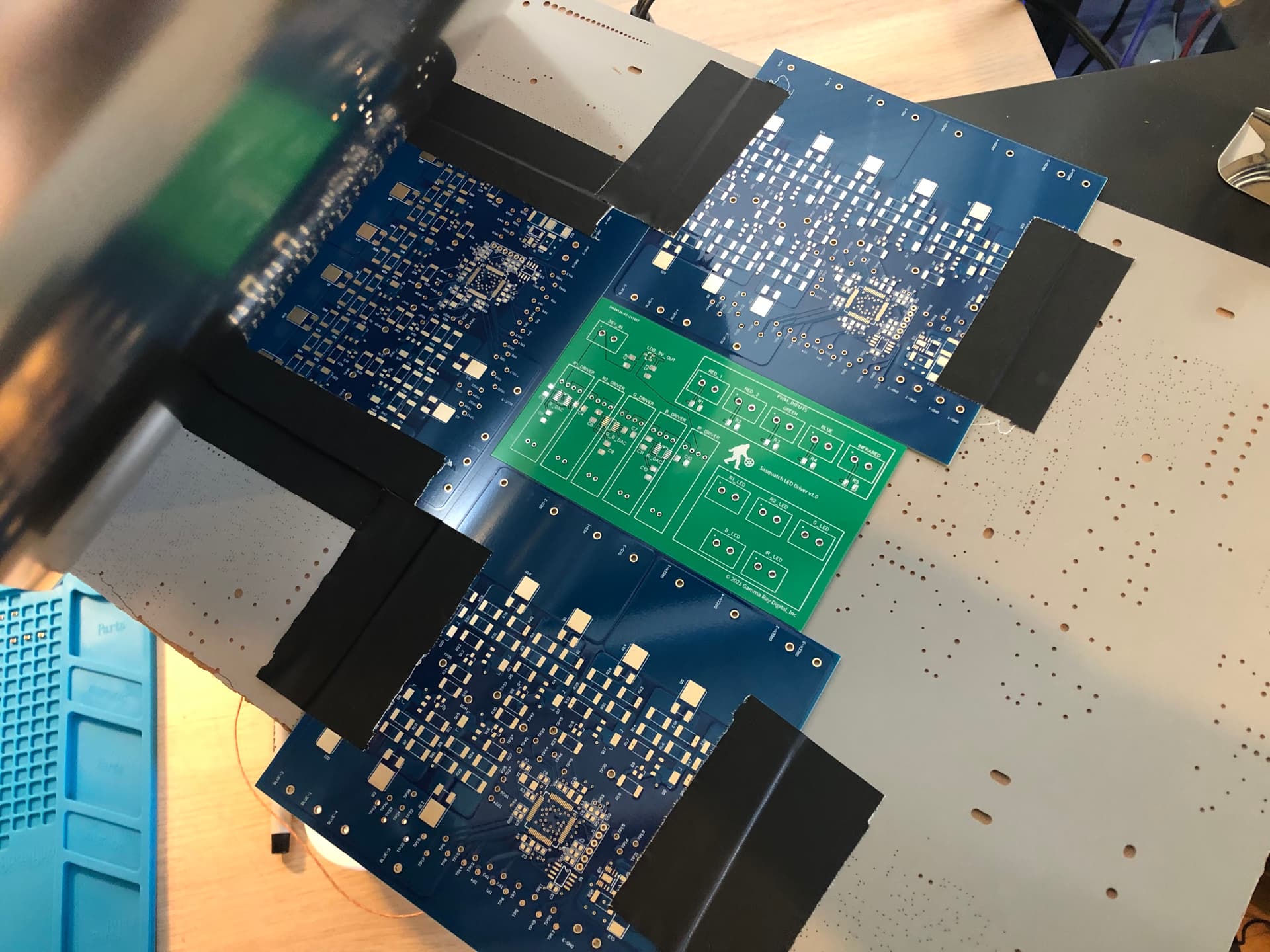
And the solder applied (takes about 20 seconds to do the whole board):
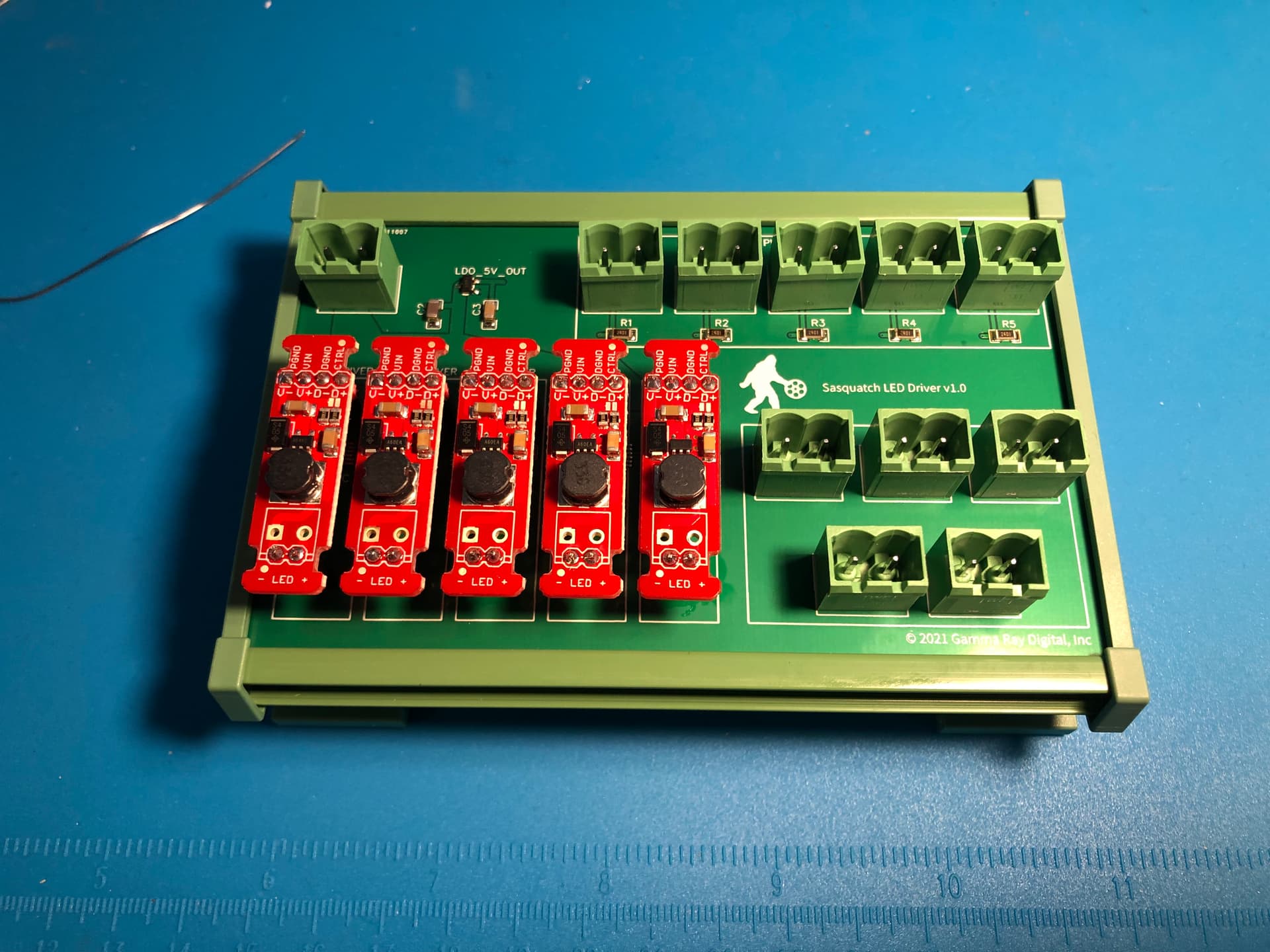
And the end result after running the board through the reflow oven and then hand-soldering the connectors:
Color coded the Femtobuck drivers, just because we had colored header pins:
Final Product. Quite pleased with this:
Hopefully testing this on Monday. But now, the Red Sox are in the ALDS playoffs and beer awaits me.
2 Likes
We have now blown traces on two of the v2.0 LED boards from testing the previous driver design, something I suspected might be problematic because they were too thin. Lesson: Don’t use auto-route in your PCB layout software without setting up some good design rules first.
So today I redesigned the board so that doesn’t happen, and took the opportunity to fix a few other things while in there:
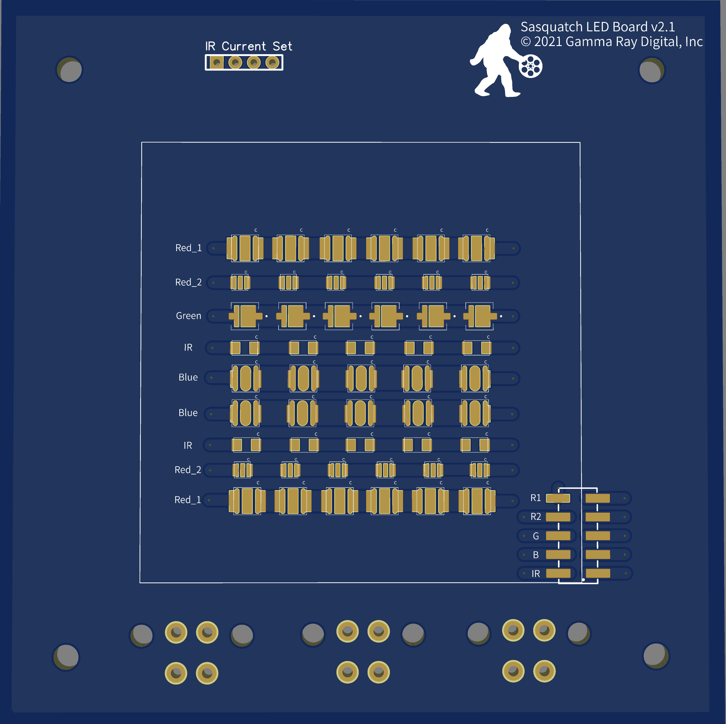
- LEDs are packed a bit tighter together. Some of the entry port on the integrating sphere was cutting off the larger 50mm x 50mm array (the white box on the board).
- Removed the 6 extra Blue LEDs we didn’t need, and had previously jumpered out. Initially it wasn’t clear if 10 would be bright enough (it is), and having 16 on there was a dumb mistake in v2.0, because it would have required more voltage than the power supply and driver can deliver anyway.
- LEDs are in straight rows, with big fat traces between diodes
- Better labeling on the silkscreen front and back, should make it easier to assemble
- All the LEDs are arranged in the same direction (anode left, cathode right), with the cathode marked on the silkscreen, which will help minimize assembly confusion
- Re-arranged the connections on the Molex hookups from the driver, to minimize spaghetti wiring on the board.
- Added slightly wider pads to each LED, which will make it easier to get probes in there to test individual LEDs, in case one is suspected of having blown. (thinking ahead. It’s inevitable!)
- Added a jumper pin block in the bottom right that all of the LED channels are routed through. This will allow for quick hookup of a multimeter in series with each channel, to test current and/or isolate channels while testing.
- Dropped the dimensions from 100mm x 100mm to 99mm x 99mm, and cut the production cost almost in half (!)
And now, another week of waiting…
[rant]
I have to say, there is a clear business opportunity for US-based PCB manufacturers here. We’re doing this in China, for three reasons:
First, the quality is great.
Second, the cost is ridiculously cheap
Third, it’s all automated - upload files and get instant quotes, pay and the process begins immediately
What’s bad about doing it in China is the shipping time - even the fastest DHL shipping is 3-4 days on top of the 4 day turnaround time. So the full turnaround time is a week, but 10 of these boards only costs around $60, including expedited shipping.
I got quotes today (a painstaking process of emailing or uploading files and waiting for a human to respond) from half a dozen US manufacturers and they ranged from $800 to $1800 (not including shipping), with turnaround times just as long.
[/rant]
1 Like
First test of the feed and takeup motors, on the test platform we built for our firmware developer to use at home. Basically, it just holds the film in place, which is all it’s supposed to do. The capstan will take the place of the hand moving the film.
With the ClearPath feed/takeup motors we’re using we can get a measurement of torque, and make adjustments from software as necessary.

2 Likes
Working on software today. This is the back-end to the front-end app. that is, it’s the application we’ll use for testing basic functionality, but also for creating the configuration files needed for each gauge/resolution of film. Basically with this application we can move the camera and lens into position, snap a frame. and then mark the position of the perforations, to be used for registration. We can also test the LEDs here, by specifying a PWM value for a specific channel and lighting it up or turning it off as needed.
Once the Transport motors are hooked up and the commands to control them are implemented in the firmware (soon) then we’ll add basic transport controls in here as well.
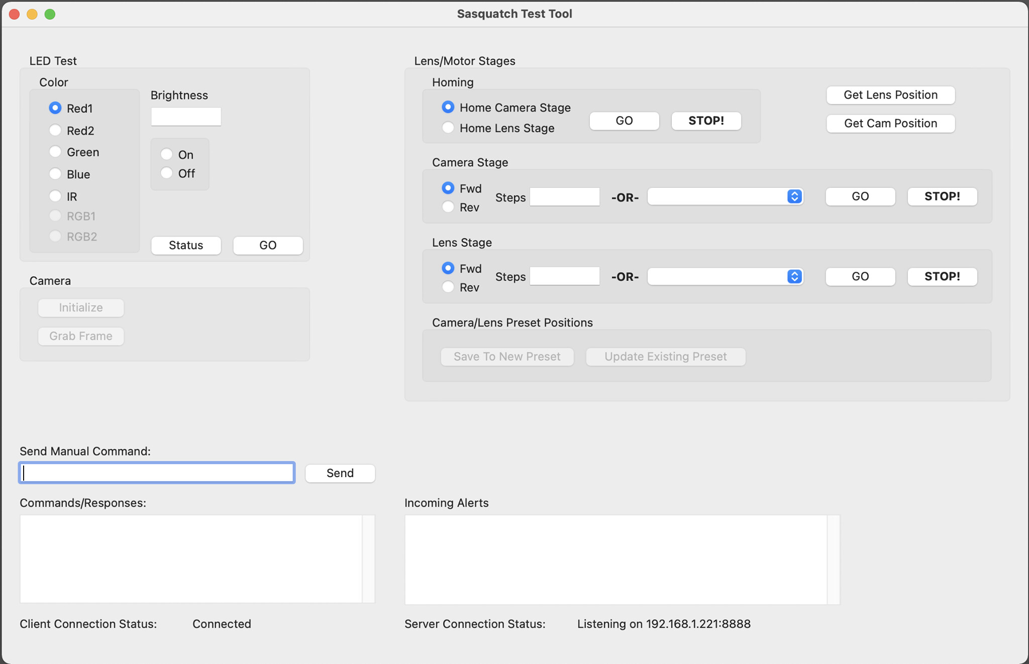
This is really only used for setup and testing, but with the programming environment I prefer (Xojo), which is fully object oriented, we can easily move most of the functionality over to the front end application just by dragging and dropping the objects from one project to the next. So the basic strategy all along has been to build a bunch of separate apps that each do one thing, like take a picture. Then a few objects from that can be dragged into this application, and voila! it can take pictures.
I’m doing the development on my iMac, but it will run on Windows. Just a compile away.
2 Likes
Some updates:
Change to the LED Driver board is being finalized. Found a dumb mistake that could short something and fry the LED board (which we did). Fixed that and figured out a temporary workaround so we can keep going while the new board is being manufactured. Getting ready to send it to the PCB manufacturer tonight. Took the opportunity to clean up the silkscreen layer as well, and made our use of the four layers on this board a bit more consistent. Might manufacture this one in black, just because that seems trendy
Been tracking down bugs and tightening up the TCP communications with the ClearCore controller all week. There are situations where the connection could get lost, and things go a bit haywire then, so lots of new error checking code being added now to handle all that, both on the desktop app and the firmware.
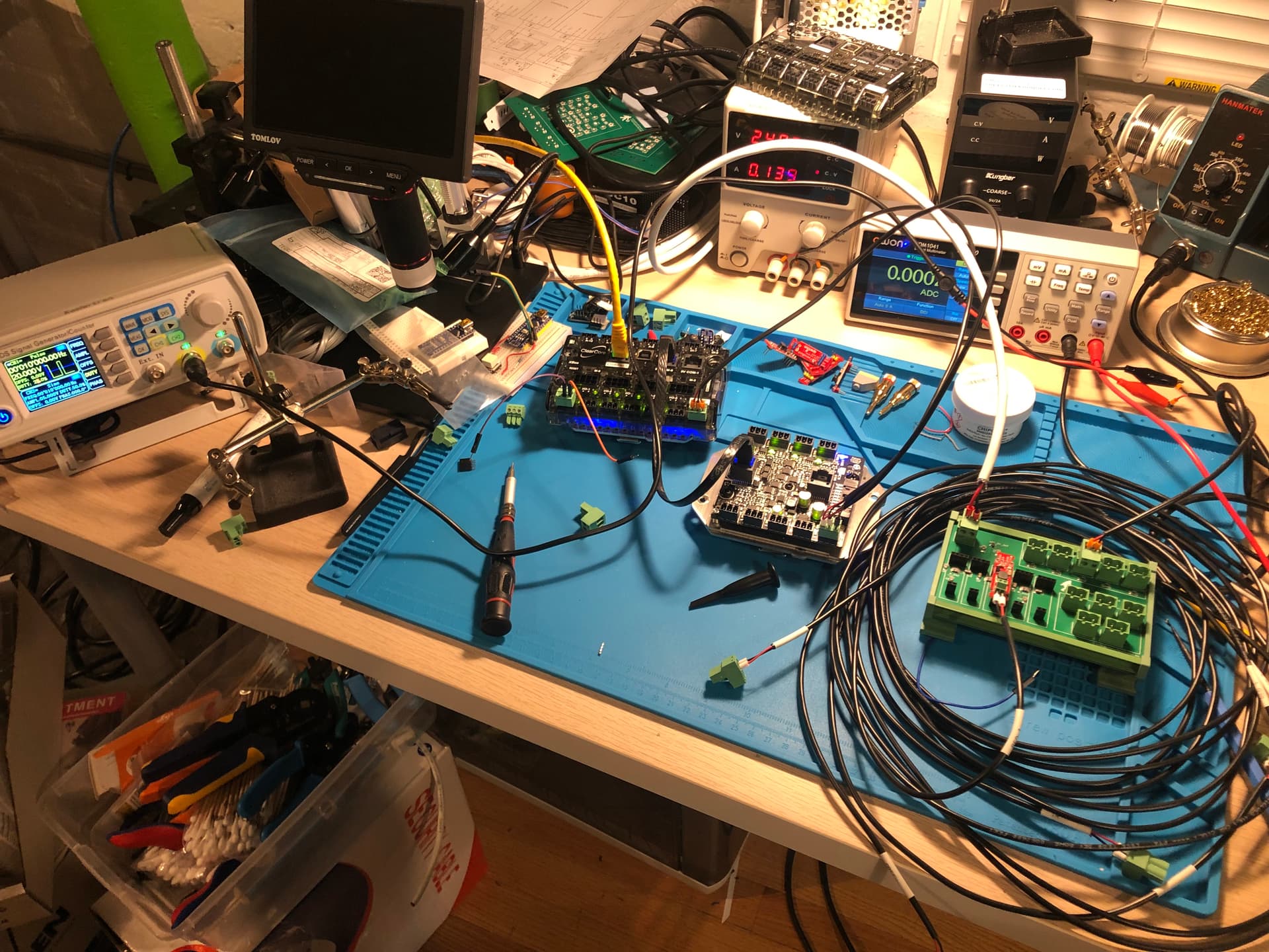
In the mean time, testing PWM->Analog voltage dimming with a function generator until we get some firmware stuff worked out. I’m guessing this is probably what @matthewepler’s desk really looks like when he’s not shooting update videos.
1 Like
Update: I ordered it in the blue seen in the mockup above.
New board arrived yesterday:
I like the blue. Here it is populated with Femtobuck drivers and connectors:
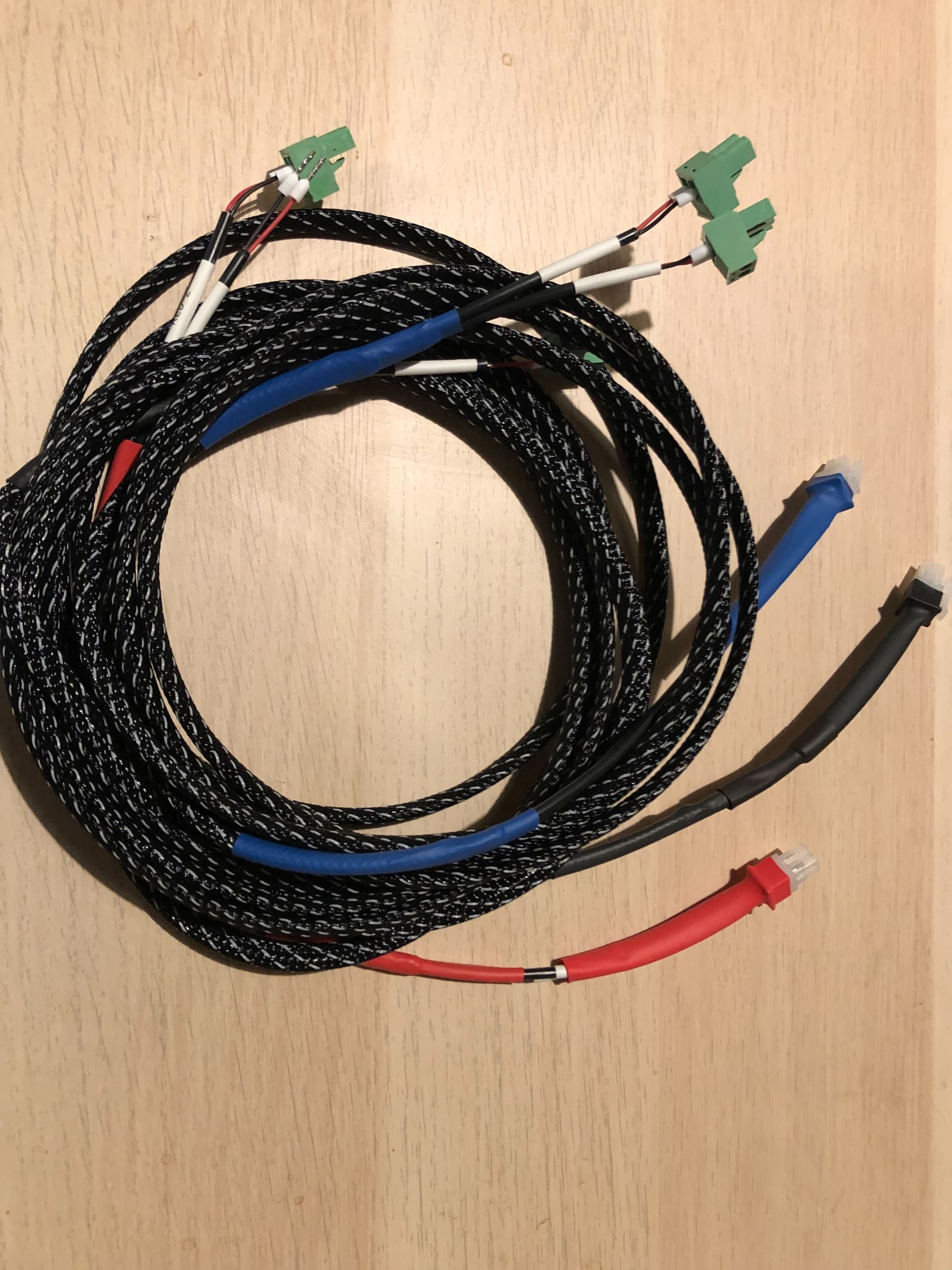
And I took some time while waiting for DHL to arrive to tidy up the LED cabling:
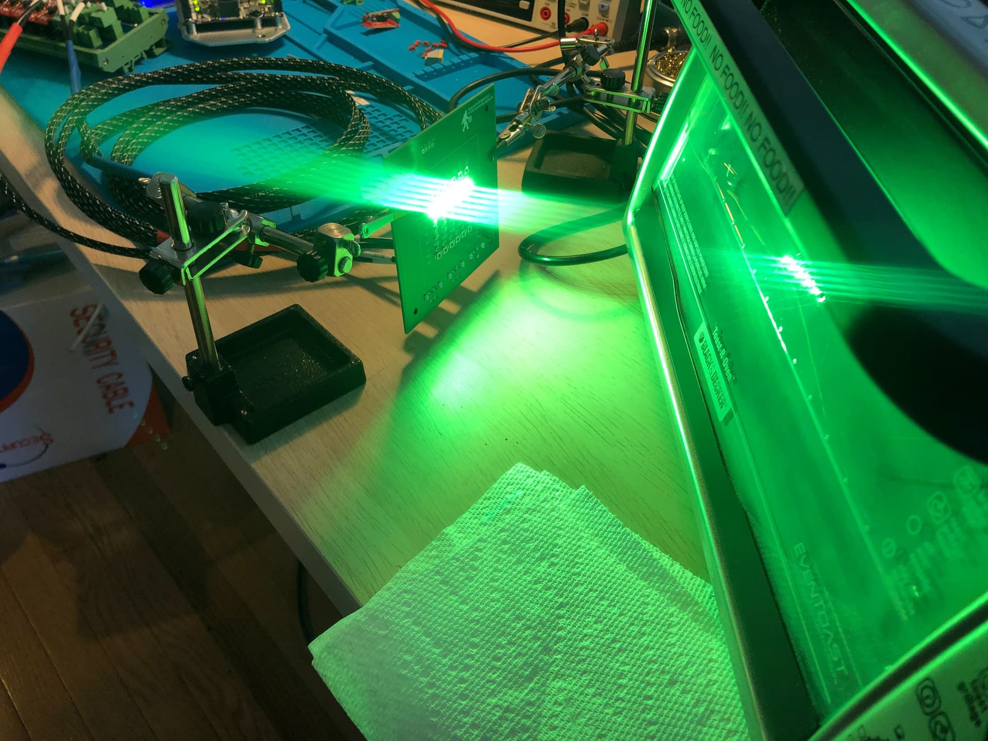
And finally! some success, though at a price. We are down to our last DAC chip and there’s a worldwide shortage of these. Can’t find anyone who has any PWM->Voltage DACs in stock until next year. We are down to one of them (though I could probably salvage some from the previous board).
Last night was mayhem - nothing was working right: I’d power on a channel and two channels would come on. Then some wouldn’t work. Checked all the LEDs, tested the PWM with a function generator. Got deeply confused because I bumped a button on the oscilloscope and was getting weird readings for a while, then figure out what was going on. And then I started systematically checking every solder joint. Wasn’t until 5 minutes before I was heading out for the night that I found a short circuit - not in the solder joint, but inside the DAC chip! Second bad chip in this batch of 10, which is kind of distressing.
So this morning I soldered up a new board, re-using the two good DACs and a new one and this is the result.
Red1:
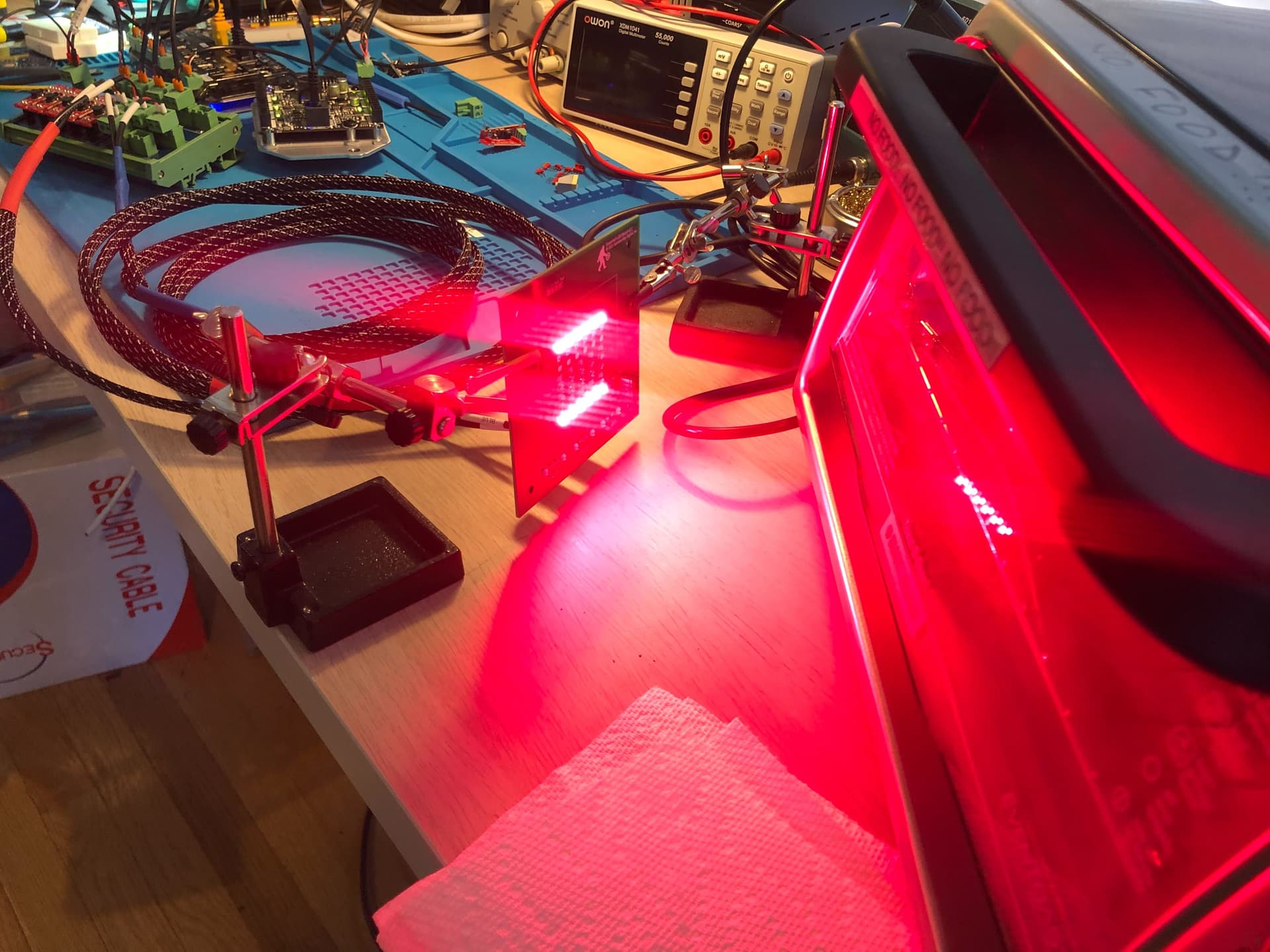
Red2:
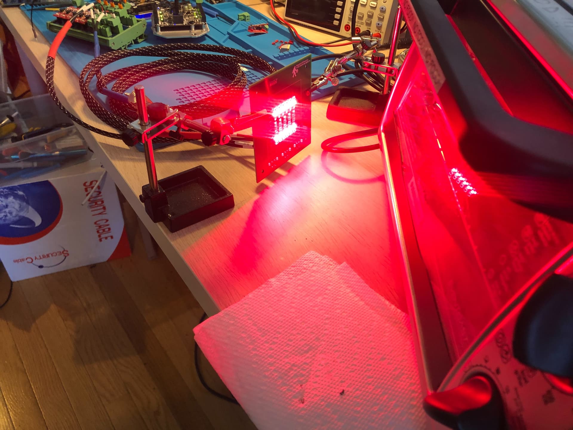
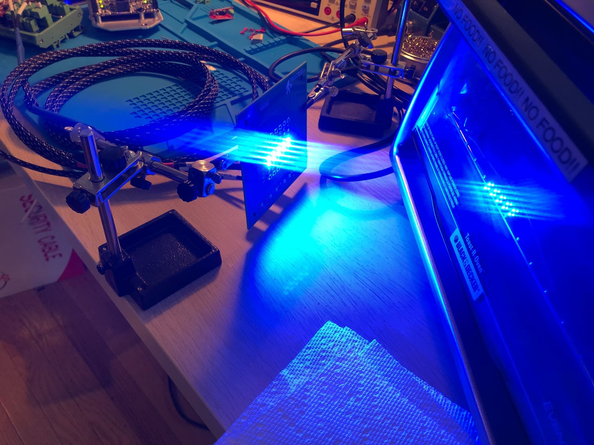
Green:
Blue:
3 Likes
Love the MDF idea and the logo is a gift to all of man kind. I really appreciate all of the updates. Really exciting to see those LEDs lit up!
I may have missed it but which DAC are you using?
Is this a correct bock diagram of what’s happening?
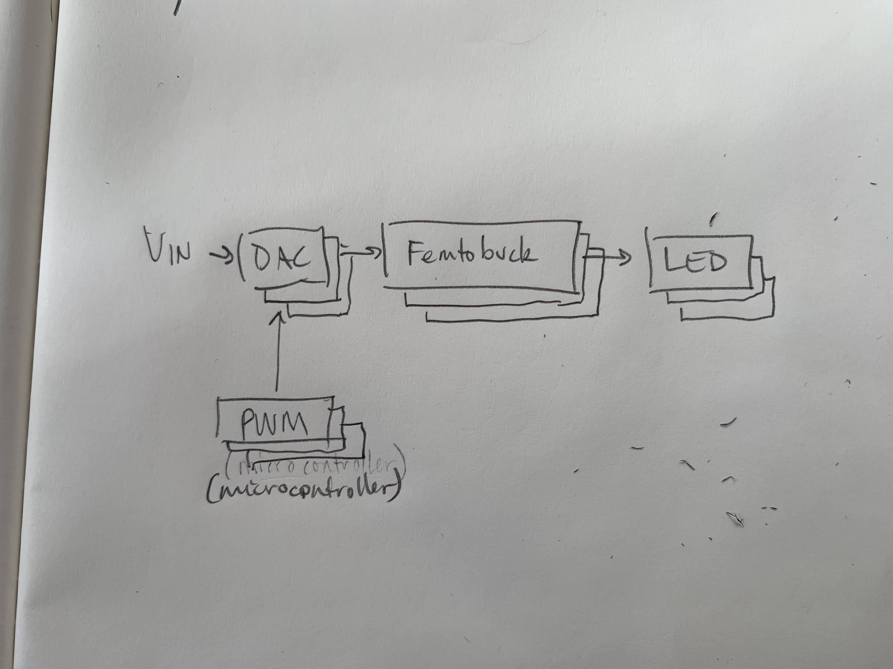
Haha. thanks. I’ve grown really fond of the logo.
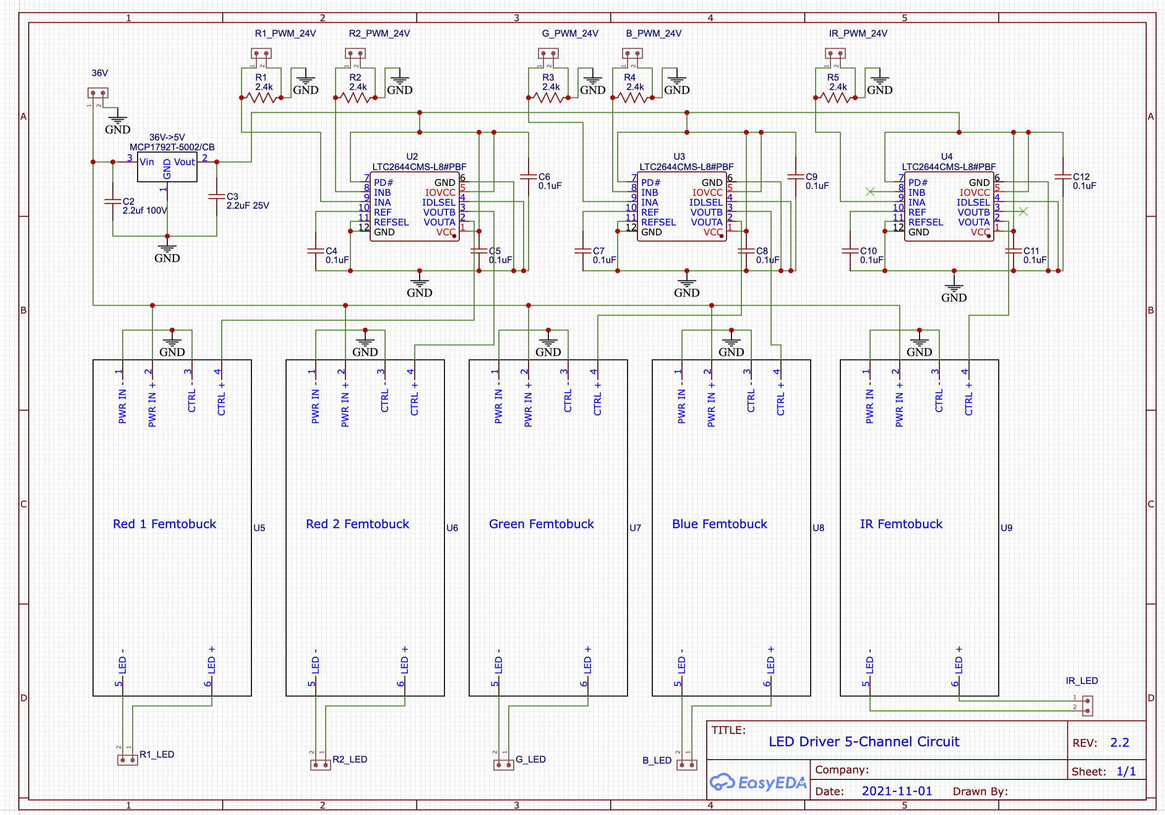
Your diagram is almost right:
The DAC is an Analog Devices LTC2644. It needs 5v to run, but we’re feeding the board 36V. There’s an LDO in there that creates a 5V branch to run the three DACs. The Femtobuck has two inputs: 36V to power the LEDs and a control signal (either PWM or analog voltage). The DAC provides the control signal. Here’s the schematic for the whole setup:
1 Like
Camera and Lens stages are assembled and working. About to load them into the scanner, so we can start doing some initial testing to find optimal positions for all the gauges we’re going to support.

The motorized lens will let us do autofocus as well, using OpenCV.
2 Likes
Thanks for sharing this -
Yesterday I pointed my FLIR (5.3K IMX530) camera at my backlight and got the dreaded flicker ![]() Been using this backlight system on my intermittent optical printer scanners for couple years with no issues but it will not work with this new camera.
Been using this backlight system on my intermittent optical printer scanners for couple years with no issues but it will not work with this new camera.
I was looking at getting the femtobucks but they are out of stock until next year.
Would the picobuck work as well? They seem similar.
…but then finding DACs is impossible at this time