It should - it’s basically three femtobucks on a single board, that share a single power supply input. Otherwise, I believe it’s the same circuit. You should look at this thread as well, if you haven’t already.
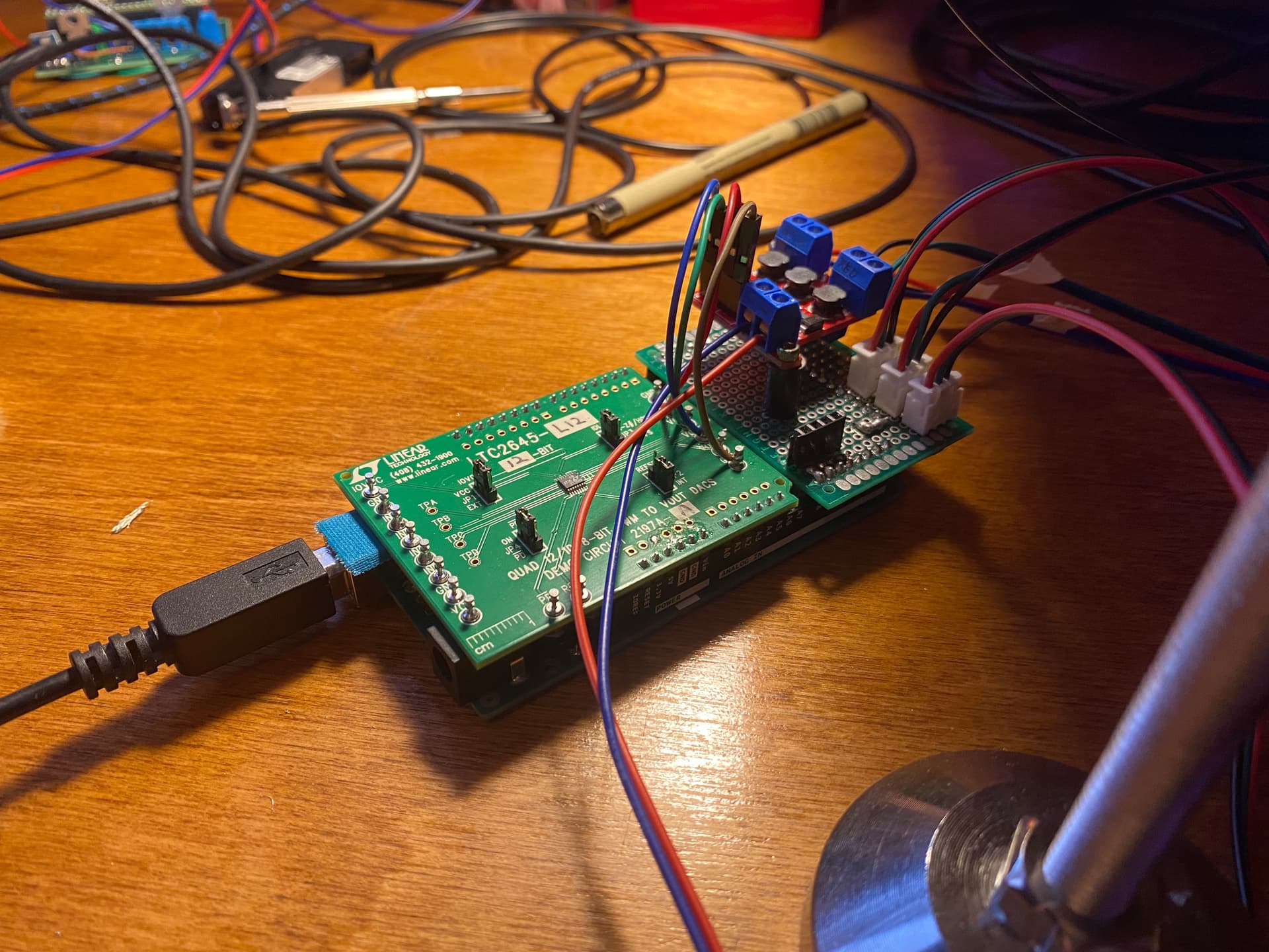
It doesn’t look like the DAC chips will be available until February, and even then, in very small quantities. We have enough to get us by as long as we don’t damage anything, and then I plan to scoop up some more when they become available again, unless our continued testing turns up some other reason not to go this way.
Also, on the DACs, we’re using one that has 2 channels per circuit. I think the same basic family of DACs has some that can do up to 4 or 6 outputs. If I was redoing this, I’d use one of those. They are a bit more expensive, but it might be worth looking to see if they become available sooner, even if you don’t use all the inputs/outputs on the chip.
It’s a smaller package, so a bit fussier to deal with if you don’t have a reflow oven or if you haven’t done much hot air soldering with small parts. But basically, the specs look like the same as what we’re using, only with 4 inputs/outputs in one IC instead of 2.
Looks like the same Quad I/O DAC i linked to above, which is slightly different than what we have. The specs are essentially the same, except that it’s a smaller package. Interesting board, looks like it’s an Arduino shield?
BTW - that looks like the 12 bit version of the DAC on that board, if the specs at digikey are correct. One of the things I want to test at some point is building one of our driver boards with a 12 bit DAC (vs the 8bit we’re using now) to see if there’s any significant difference.
They appear to be drop-in replacements for one another.
Keep in mind that both the pico and femto have a range from 20% to 100%. Given that you are going for RGB only, that should work. For other setups such as W + (light correction with and RGB combination) the starting point at 20% of these require to balance the correction at the 20% starting point.
PS. If I knew there was a market for $75 DAC boards, I would have design it with an actual DAC (not a PWM to DC converter) and a Raspberry Pico to handled them.
From what I learned testing the constant-linear driver, the significant difference is handling low output levels, which makes sense given the exponential nature of light.
But with the LED driver starting at 20%, the most relevant portion of more resolution is not usable.
As commented above, in single channel setups (like Sasquatch), the use case may not require it. When working with W+ setups (additive/corrective light) then it would make a significant difference, but to see it a 0-to-100% range driver would be required, and obviously a PWM output with matching resolution.
I got the DAC board and also the PicoBuck today. The board is literally an Arduino shield.
As a quick test I plopped the DAC shield on top of an Arduino Mega, and connected one of the outputs to the picobuck. Added a potentiometer to one of the analog pins on the Arduino.
No flicker! and it’s dimming.
Now it’s kind of shitty dimming, it starts pretty bright already, there’s not much dimming range. I’m sure there are ways to improve that - this was a very crude test but it did what it was supposed to do.
Would be nice to take advantage of the 12 bit DAC for better dimming range, maybe using a better microcontroller than Arduino and or something else to replace the picobuck? I need to wrap my head around all this I’m not the most versed in electronics.
I have to figure out how to regulate the voltages for my LEDs on the pico. I got a 36v, a 34v and a 27v. Plan is to feed the max voltage(36V) to the pico and use step-down converters on the 2 outputs that need 34v and 27v.
the picobuck/femtobuck are constant current drivers. As long as you don’t exceed the driver’s voltage you’re good. The number to look at is the current draw of your LEDs. By default the pico/femtobuck outputs 350mA current to the string of LEDs attached to each channel. If those LEDs combined only draw 10V, that’s fine, you can still hook it up and give it 36V input. But if your LEDs require significantly more current, or significantly less, then you may have issues. Note that you can almost double the current output of the picobuck by (removing? swapping? I’d have to look it up) the current set resistor on the board.
What kind of current do your LEDs require? Can you post the datasheets for them?
Looking at the datasheet the pico is not going to work for my LEDs at their full potential. I will solder the jumpers on each channel to increase the amps to 660ma, it will work for now while looking for other boards.
the datasheet doesn’t match my real life results as I can make them brighter by using 36, 34 and 27 volts.. but it’s in the ballpark see below:
running them at less than their rated current isn’t bad, and could potentially extend the life of the LEDs. If you’re getting enough light at 660mA then I wouldn’t worry about that.
If the lights are getting brighter with more voltage, it’s probably because there’s a relationship between voltage and current - adding more voltage basically gives you more current to work with, and that will make the LEDs brighter. I bet you’ll see less of a fluctuation when you change the pico to 660mA.
@robinojones
If I understand the datasheet of the AL8805 correctly, when driven by DC the range is from 25% to 100%. I think that’s what you mean by poor dimming range. That’s what I was mentioning on my previous post.
Drive with DC voltage (0.5V < VCTRL < 2.5V) to adjust output current from 20% to 100%
In the picobuck page there is also a reference to it:
Dimming can be done by an analog voltage (20%-100% of max current by varying voltage from .5V-2.5V)
I haven’t used the pico/femto but what follows seems to indicate that the full 0-100% is not available when driven by DC, only when using PWM.
or by PWM (so long as PWM minimum voltage is less than .4V and maximum voltage is more than 2.4V) for a full 0-100% range.
@friolator in an earlier post in the subject indicated that when using PWM the driver output had some residual of the PWM.
If those voltages are the Vf, what it means is that you can expect the LED forward voltage to be X-X when the current is Y-mA.
The pico/femto are switching current regulators, so as long as the Voltage you are using is higher than the LED Vf, the regulator will maintain the selected current.
In other words, all 3 may be driven with 36V, and the pico will maintain the selected current (660mA) if you go for the higher. You can measure the voltage across the LEDs with a multimeter and confirm the operating Vf.
That’s a good point - the thing is that in my initial tests with the camera, it’s showing that I need very low exposure times to avoid motion blur - and to compensate I will need a lot of light especially for denser negatives. maybe this will be enough.
I will solder the jumpers now and see how it is at 660ma.
Yes these are the forward voltages.
thanks for that - I will try that code and see if I get more range.
Incredibly helpful - thank you both for everything!
I just saw this info on the Sparkfun Picobuck hookup guide. Looks like I should be able to go to 1amp. Will try that too.
Alternative Current Output
It is possible to increase the maximum current of the PicoBuck board up to 1A per channel; to do so, replace the three current sense resistors with smaller values. To calculate the new value for the resistor, use this formula:
ILED = 0.1 / Rset
Thus, for a 1A current, you’d want a 0.1Ω resistor. Don’t forget to be wary of current ratings. At 1A, the sense resistor will be dissipating 1/10W, so you probably want a resistor of at least 1/8W rating. The package is a standard 0805.
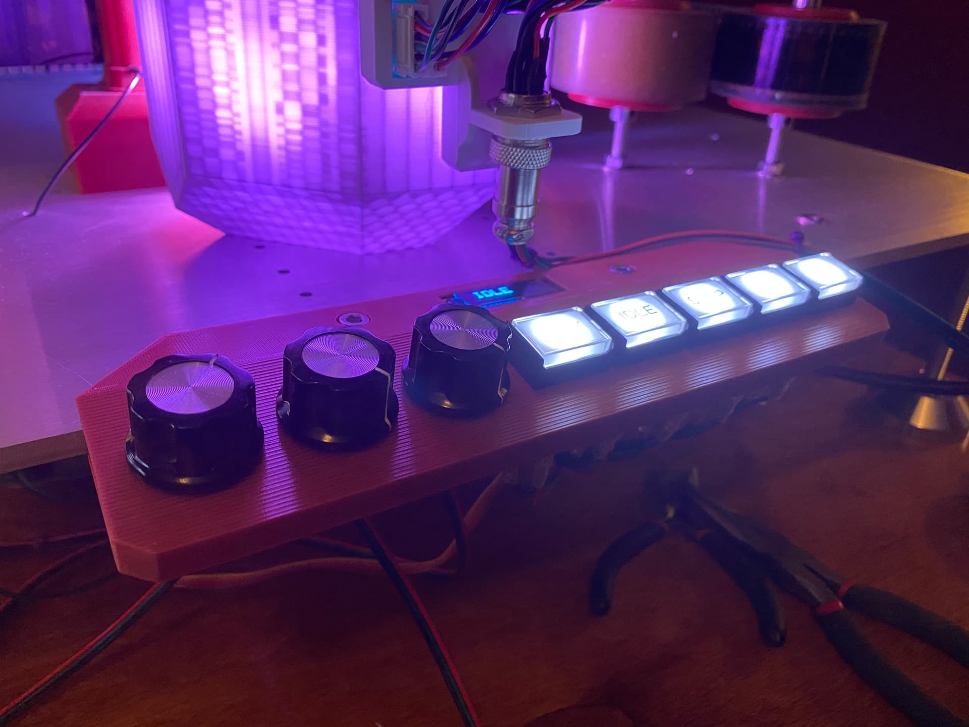
I made a small prototype board and installed some potentiometers - it’s so bright it hurts to glance at it and no flicker.
Code will need to be tweaked to improve the range but at least I can continue working on camera trigger. I got a 2 channel scope today so I can troubleshoot the trigger - the camera was randomly losing perfs, this will allow me to troubleshoot that
@PM490 i looked at the 16bit pwm code you linked but I can’t get it to work with arduino mega. I will look at this again soon as I was busy doing the electronics.
If you are looking for a simplified version of the 16 bit PWM with Mega, this is the code I made to test the Kinograph drivers. The output is 16 bit PWM. The input is analog 12 bit with the Mega ADC inputs.
It also converts it from linear to exponential (pow function) to make the feeling of the potentiometers-to-light output linear, taking advantage of the 16 bit range on the output.
PS. Keep in mind that only certain outputs would work with 16 bit PWM.
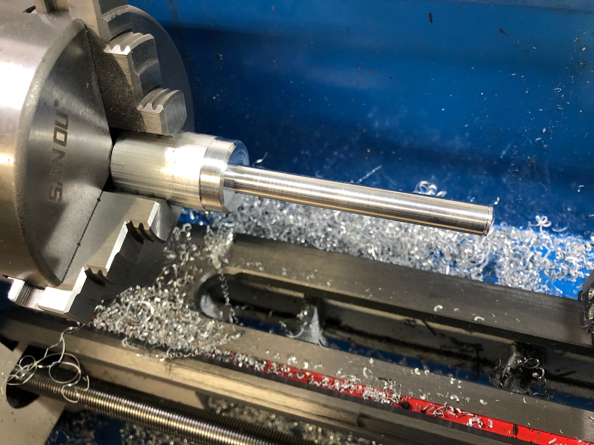
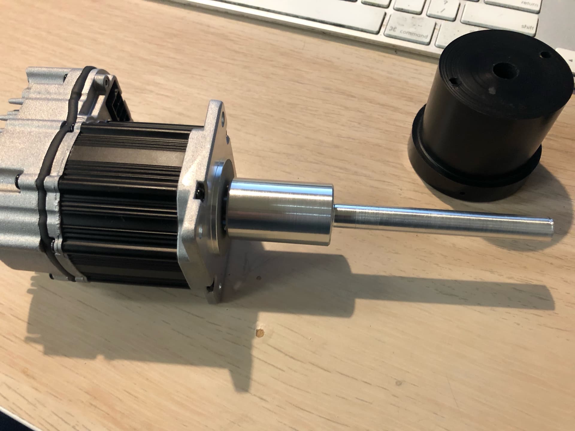
The capstan drive is something I’ve been thinking about for a year, but finally came up with a setup I like.
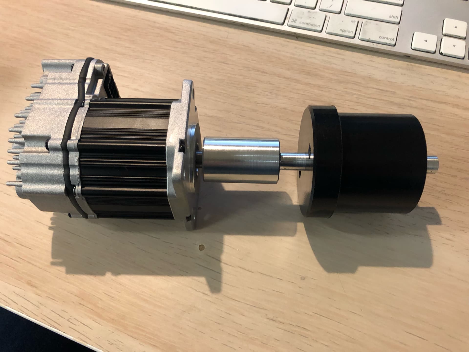
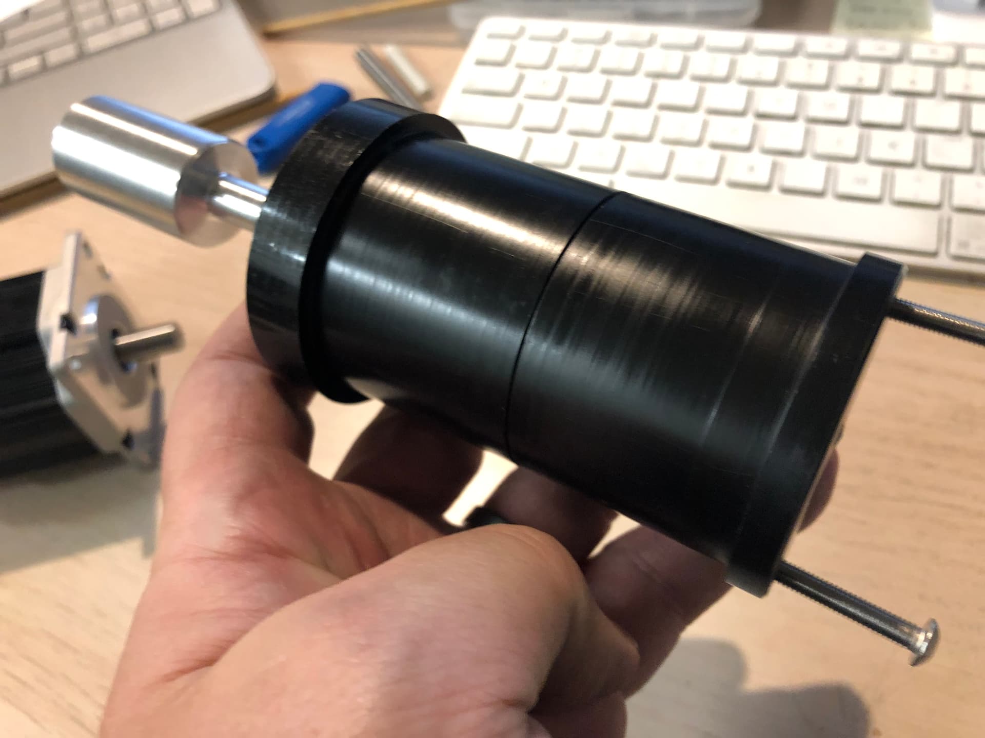
Unlike the other PTR rollers, which are free spinning on bearings, the capstan PTR has to be fixed to the motor shaft. The motor has a 3/8" shaft that’s only about 1" long, but the motor is mounted on the back of a 3/8" thick piece of aluminum, so it’s set back from the face of the scanner. This means we can’t have a set screw that holds it in place without the option to remove the fatter PTR hub as well. So, multiple parts.
Starts with some aluminum and a really crappy lathe:
This was 1" stock, and it had to be turned down to a 3/8" shaft:
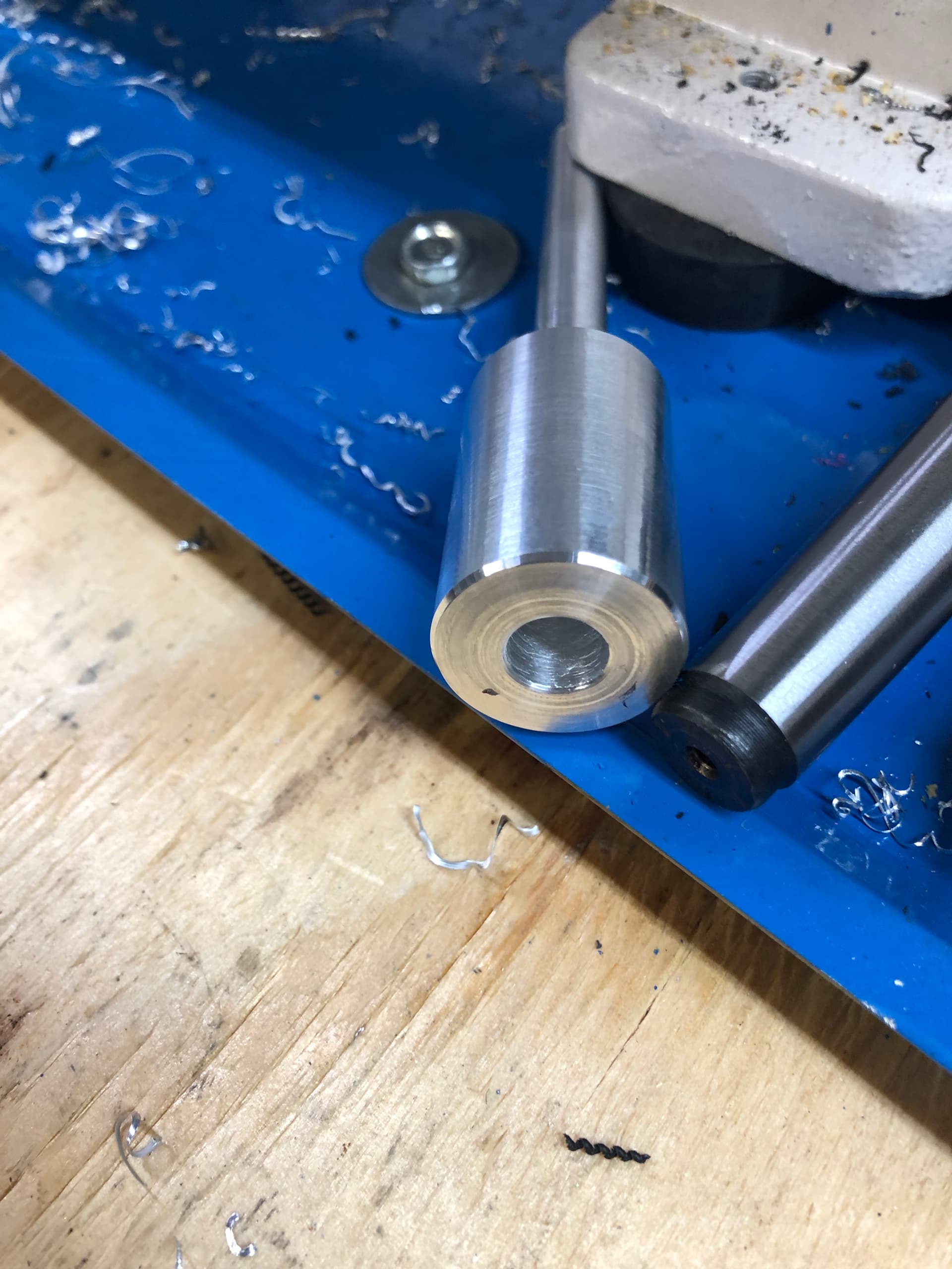
The PTR hub was turned from Delrin like our other ones, but this one was cut in half. It slips over the 3/8" shaft, and we’ll cut that shaft to length and thread the end for a nut. This will secure the bottom of the PTR hub to the shaft.
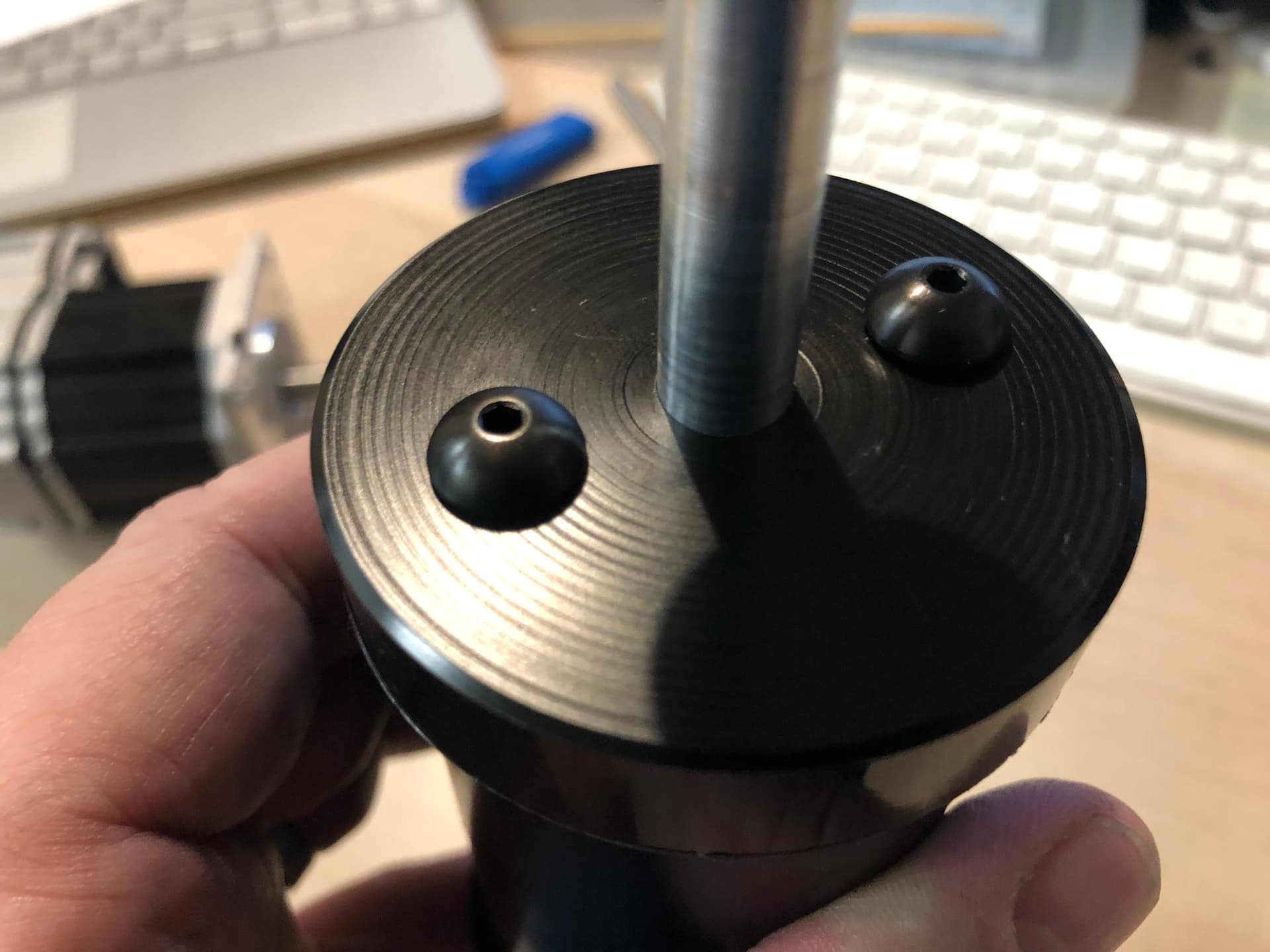
Next there are rubber O-rings (not pictured) that slide over the delrin and sit between its flange and the metal ring of the PTR roller. The other half of the hub slides into the PTR roller, and is secured to the base half with two 90mm M4 screws. This is an approximation, because the motor shaft hasn’t been cut yet, and because the 90mm screws are in the mail.
A while back we ditched the Schneider MDrive stepper motors that we were going to use for the camera/lens assembly. They were a bit too long, and as NEMA17 motors, required a step-up adapter to fit the NEMA24 linear stages we’re using. So we replaced them with simple, cheap low profile steppers. More than powerful enough, but they require external drivers, unlike the Schneider motors, which were integrated.
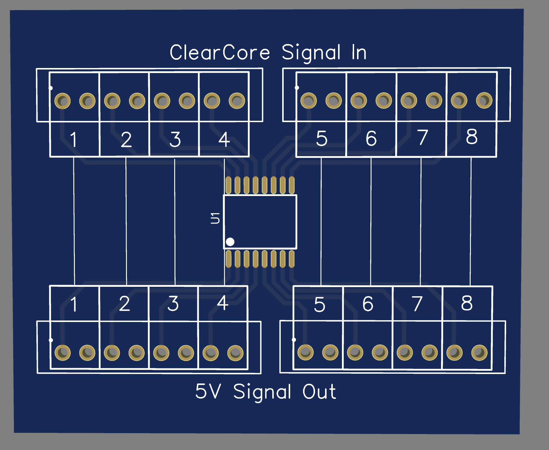
Those external drivers happen to require a 5V PULSE and DIRECTION signal from the controller. If you’re using an Arduino, that’s fine. But our ClearCore outputs 24V, which is common for industrial automation tools. The ClearCore has an internal 10k pullup resistor for each of its signal outputs. So geting it into the <5V range is as simple as wiring in an inline 2k resistor. Our LED driver board has these built in for the PWM inputs, but for the stepper motors, we were using temporary cables, which have a thru-hole resistor on a thin piece of breadboard, with the wires soldered to it, and heatshrink tubing to hold it all together. It’s ugly.
So, the solution is to make another DIN-rail mounted breakout. This will have 8 input/output pairs. It’s wired through a $4 resistor array. Total cost for board manufacturing (not including shipping) was $2 from JLCPCB (for 5 of them). each board gets about $8 in parts. Should be here next week.