Sasquatch 70mm scanner

So this board didn’t work out properly. Let this be a lesson to double check things…

Easy EDA, the tool I use for PCB schematics and layout, has a vast user-contributed library of parts. But that doesn’t mean they’re accurate. The first board came back with completely the wrong footprint for the resistor array I purchased.

Also, I didn’t realize that the DIN rail mount I bought was vertically oriented until it arrived, so that would have meant the board would be rotated 90 degrees. Functionally no difference, but would have driven me nuts.

So, new board is here, with the proper resistor array footprint, and a new vertical orientation.

2 Likes

Back to some mechanical stuff today. Finalized the mounting system for the free-spinning PTR rollers:

These are generic shaft flanges you can buy on Amazon with 24mm spacing between the holes (across the flange). There’s one of these on the face going into the deck plate and another on the back, with set screws that hold the shaft in place:

They’re held in place with low profile M3 bolts and lock nuts. The total depth of these two flanges combined is about 30mm, which seems to be pretty solid, with no flexing so far. The shafts themselves are 10mm diameter and are a pretty snug fit inside these flanges, so they seem to be nicely perpendicular to the deck plate. We have an alternative mounting method if need be (some spacers that match these holes, which we had made previously), which would give us an additional 15mm of purchase on the shaft, but I don’t think that’s going to be necessary

The Capstan motor is now mounted with proper lock nuts on the back as well, and as you can see from the picture above, the powder coating done by the place we used locally is pretty crappy. Spent a lot of money on that, but they didn’t properly prepare the metal and there are lots of places where it’s peeling off, especially near mounting points. Black sharpie? have to figure out how to conceal that.

Finally, all 5 PTR rollers are installed, free spinning:

And they have spring plungers to mate with the inside of the PTR. These keep it from riding off the hub, And were significantly more work to install than I had anticipated:

1 Like

Once everything was assembled, it became apparent that there’s a fair bit of play in the roller shafts, which causes them to not be perfectly perpendicular with the deck plate. This causes the film to want to drift off the end of the PTR. This is bad.

So, this afternoon I designed some new blocks that we’ll have machined. These go on the back of the deck plate and have a very snug fit around the roller shaft, with about 65mm worth of sleeve for the shaft to sit in. This will be bolted from the front, and the flat front surface will sit perpendicular to the deck. This should eliminate that problem…

And then I started work on the capstan, but quickly realized the previous design has some problems as well. So that has now been completely redesigned and will also be manufactured at the same time as the other parts. There are three pieces, the shaft, the inner and the outer hub.

The shaft sits over the motor shaft to extend it through the hub, and has two set screws to lock it in place.

There’s a “paddle” that that registers with the inner part of the hub. The shaft continues up until it gets to the outer part of the hub, where an M8 thumb screw will lock it together.

The two halves of the hub interlock with one another, and rubber o-rings against the PTR roller will keep that from slipping. This is ultimately a bit simpler to use than before, but of course, more complicated to make.

And it’s a perfect fit on the deck plate, with the spacing just right.

Hopefully we’ll have these parts back in a week or so.

2 Likes

Fantastic documentation. Jealous of your machining skills! I liked the idea of using those flange bearings as opposed to the pillow block ones I’ve been using. @Jeffcrowl mentioned that to me today as well.

Jeff was able to find this traction sleeve material for use as a PTR sleeve, which sounds similar to what you are doing. What material are you using?

So are you suggesting that that slides over the roller hub and is the capstan material itself, or that it’s used to hold the removable capstan PTR in place?

My setup used a standard PTR and the hub for it is delrin in two halves. Because the inside of the PTR is aluminum, it slips against the delrin hub. So the solution was to machine the delrin hub to be pretty tight, then put a rubber o-ring on each of the flanges of the Delrin hub.

So basically the PTR exactly fits the Delrin hub, and the O-Rings go between the hub flanges and the ends of the aluminum tube at the center of the PTR. This does two things:

  1. Provides friction to prevent the PTR from spinning
  2. Provides some squishiness that allows the nut that holds the two halves of the capstan hub to squeeze things nice and tight.

In theory, there should be no slippage with this setup and it should transfer the power from the capstan motor directly to the film

That being said, if this traction sleeve material isn’t too sticky, I could almost see it as the outer surface of a Delrin hub, the part the film actually comes in contact with. But I think I’d need to see it first to know. Interesting stuff.

These new parts are on their way from China now, and I should have them in a couple days. Can’t wait to get them all installed so I can move forward!

New parts shipment has arrived!

From left to right: The new shaft sleeves for the PTR Rollers, A bar that holds down the front end of the camera/lens sled inside its cabinet, the two halves of the Capstan PTR hub, and the capstan motor shaft extension those hubs lock to.

The PTR shaft sleeves came out really nice, perhaps a bit too nice. The fit is very snug, so I think I’ll be spending the afternoon trying to make it a bit easier to slide the shafts in.

This is the shaft extension that goes on the capstan motor. There are set screws on the other side of the base of this, which lock into a channel on the motor shaft.

The lower half of the PTR hub slides onto this:

and then the upper half onto that, with a thumb screw to hold it all closed.

On the underside of the outer hub half will be the o-ring mentioned above. The purpose of this is to create a squishy layer between the hub and the metal core of the roller. This will provide the friction needed to keep the PTR from slipping on the core, hopefully.

I’ll post some more photos when everything is on the scanner, later today hopefully.

2 Likes

All in all I’d call this a successful upgrade to the scanner. With the new shaft sleeves installed there is zero play, and the film rolls over each roller perfectly smoothly and without telescoping on the takeup reel.

Motor with shaft extension installed:

Motor with shaft extension and complete capstan hub:

Shaft Sleeves installed:

This is a nice shot because you can see the whole thing from the side. The shaft goes almost all the way into the sleeve, which is held perfectly perpendicular to the deck plate by the flat end of the sleeve.

capstan motor installed. This is the motor, the bottom half of the capstan hub, and a PTR. The bottom half is attached to the shaft with some set screws, so it stays attached, but the outer half and the PTR capstan are removeable:

@matthewepler - this is the o-ring mentioned above, on the outer half of the capstan hub:

and with the PTR roller installed. You just need to get it thumb tight with the nut at the end and it seems to be completely slip-free:

Complete capstan assembly:

It’s keeping the film perfectly in line with the gate:

The film can be threaded A or B wind. In an eventual firmware upgrade, we’ll allow for A->B and B->A wind as well, like the ScanStation. That can be handy sometimes when you get film that’s incorrectly wound.

5 Likes

This is great. Love the simple film path. I will definitely steal that o-ring idea from you! Thanks for showing me that.

I totally agree with supporting multiple winding strategies. You never know what you’re going to get!

Did you say those PTR hubs are machined delrin? That’s what I think I see but wanted to ask. Are you willing to share the design files for those? I’d like to try them against the pressure plate design I’m using to see how they compare. And I want to feel that satisfying click of the roller mounting!

Thanks!

They are delrin. Do you mean the regular PTR rollers or the capstan roller? I don’t know if I have a cad file for the regular rollers but it would be easy enough to whip one up. I made the regular rollers by hand on the lathe (not CNC). The capstan roller is cad and was CNC machined.

The capstan roller would be great.

UPDATE
@friolator I think I get it now. I was confused about the threaded part of the capstan shaft. I thought it was an off-the-shelf metal part and couldn’t figure out how you fixed it to the hub. Now I’m seeing it’s all one plastic piece. You had that CNC’d, yes? Even the threads? That’d have to be one spiffy CNC at least 5 axis, no?

Hi Matthew - not exactly. The whole capstan roller assembly consists of three parts: There’s a shaft extension sized for the specific ClearPath motor we’re using. This is the part with the “paddle” and the threaded end. This is aluminum, and is anodized black.

The other two pieces are the two halves of the capstan assembly itself.

Of course, this is all for 70mm, so it may or may not be useful to you, but here are the stp files:

SasquatchCapstanParts-Kinograph.zip (80.2 KB)

This was all outsourced and done on a CNC. Probably a 4 or 5 axis machine, but I don’t know exactly. I don’t know if they did the threading on the CNC or afterwards with a die. I’m a big fan of the idea of thread milling but haven’t tried it myself.

I’ve stopped using Fusion360, because Autodesk is an evil company and they constantly change the user interface in ways that require you to re-learn their app over and over again. Their CAM software works great, but I’m not paying money to have to keep dealing with their BS. I switched to ViaCAD and DeskProto for CAD and CAM and am pretty happy, though I’m still learning DeskProto. Fusion’s CAM can do thread milling, but you need your CNC to be super tight to make that work, especially in materials like aluminum.

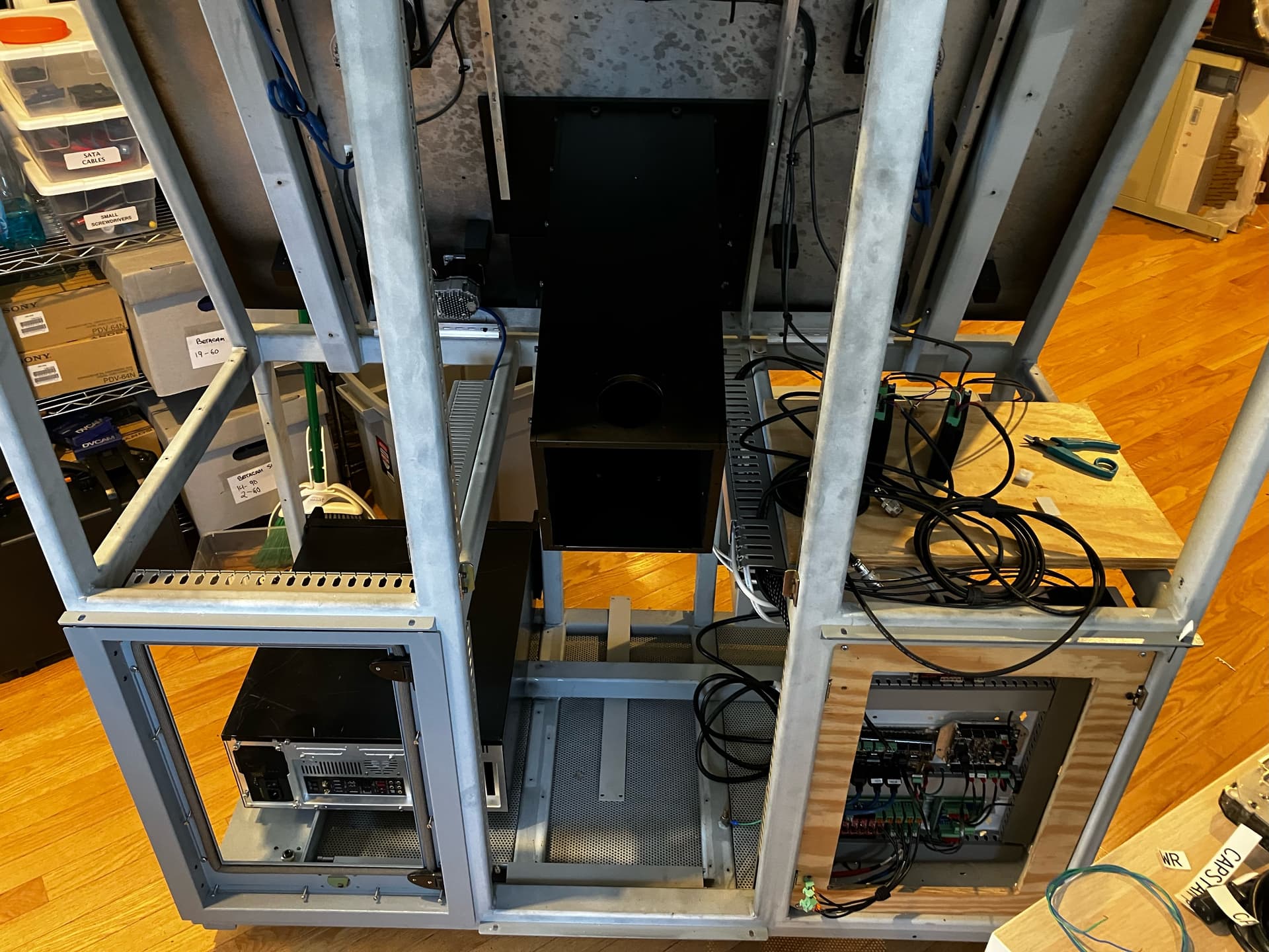
Been a while. Like, a long while. I won’t bore you with the all gory details, but suffice it to say that buying an office space for your company is a nightmare, one we still haven’t woken up from and one I don’t recommend. Most of Sasquatch is packed away because we thought we were moving in April. Then August. Now, who knows, but it has to be in the next 6-8 months because the building we’ve had our office in for the past 13 years is being torn down to make room for a shiny new building next year.

Which means everything in terms of hardware basically froze in February when we thought we had lined up a new place, and is currently in boxes. So I have started concentrating on the front end software again and after quite a few revisions, I’ve got a GUI and an underlying architecture I think I’m happy with. Because I can’t actually test with the camera or transport right now, this is pretty much a framework to plug all the other code I wrote over the past couple years into (camera interaction, ClearCore controller communications, etc).

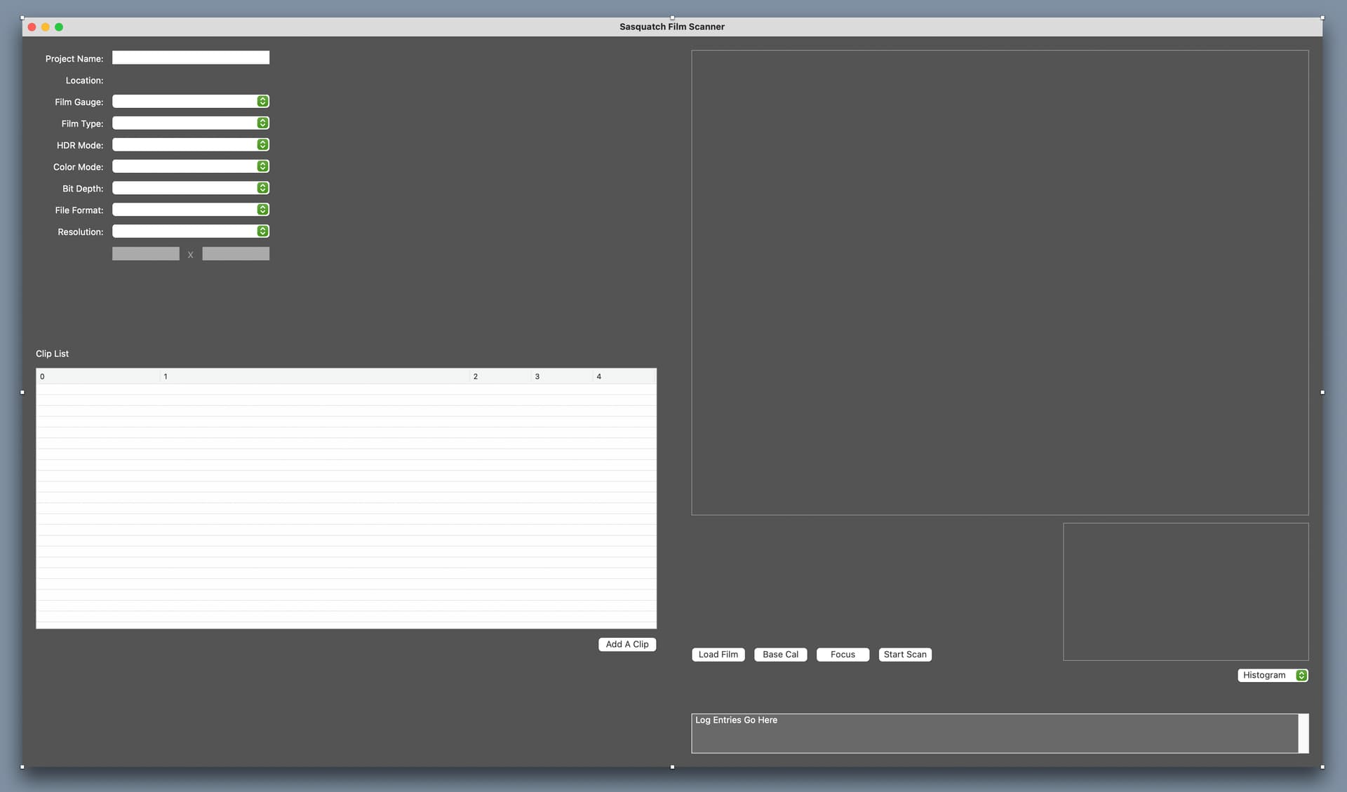
The app looks like this when you run it. Lots of unused space, but see the second image:

Here you can see the faint outlines of where the preview window will be (the large box is where the last captured frame will be displayed), and the scopes (above the Histogram popup menu).

We’ll have a histogram at first (comes for free in OpenCV basically), and may add in an RGB Parade as well. Though honestly, we almost always use the Histogram in our ScanStation and nothing else, so I’m not sure we even need the option. In any case, any additional scopes would come later.

above the row of buttons (load film, etc) will be the transport controls: FF, RW, Stop, frame forward and back, and perf racking controls. This will also tell you the current location in the reel.

One of the things I like about this setup is that I’ve made it so that almost everything important lives in XML files. When you open the application and this window appears, under the hood it loads up an XML file containing all the values that can be used in the various controls you see. Then it loads up a default project file (also XML) or if you go to File/Open it opens a saved file. This project file contains the selected values and it modifies the controls to show those.

Why does this matter? because once all the logic is in place, we can add another film gauge simply by modifying the appropriate XML files. it won’t require any coding, or recompiling of code. Just add a new entry to the default settings, a new file describing that film gauge, and that’s it.

For example, here’s what the Resolution Presets file looks like:

<Defaults>
	<Resolution id="0">
		<ResX></ResX>
		<ResY></ResY>
	</Resolution>

	<Resolution id="1">
		<ResX>4096</ResX>
		<ResY>3112</ResY>
	</Resolution>
	
	<Resolution id="2">		
		<ResX>4096</ResX>
		<ResY>2160</ResY>
	</Resolution>
	
	<Resolution id="3">
		<ResX>8000</ResX>
		<ResY>6000</ResY>
	</Resolution>
	
	<Resolution id="4">
		<ResX>12000</ResX>
		<ResY>8000</ResY>
	</Resolution>
	
	<Resolution id="5">
		<ResX>14000</ResX>
		<ResY>9000</ResY>
	</Resolution>
</Defaults>

If we decide that we want to add a resolution for an aspect ratio we’re not currently supporting, we just need to add an entry here and it will instantly appear in the popup menu next time the app is loaded.

Because our camera and lens are on independent motion-controlled stages, we will have an XML file for each film gauge, because each film gauge will require different positioning. Also in that file will be the start coordinates for the sensor’s ROI, the maximum resolution we can support at that magnification, etc.

So if a client comes up with some crazy film format we haven’t thought of, we just need to generate a new XML file for that format, and it’s instantly available.

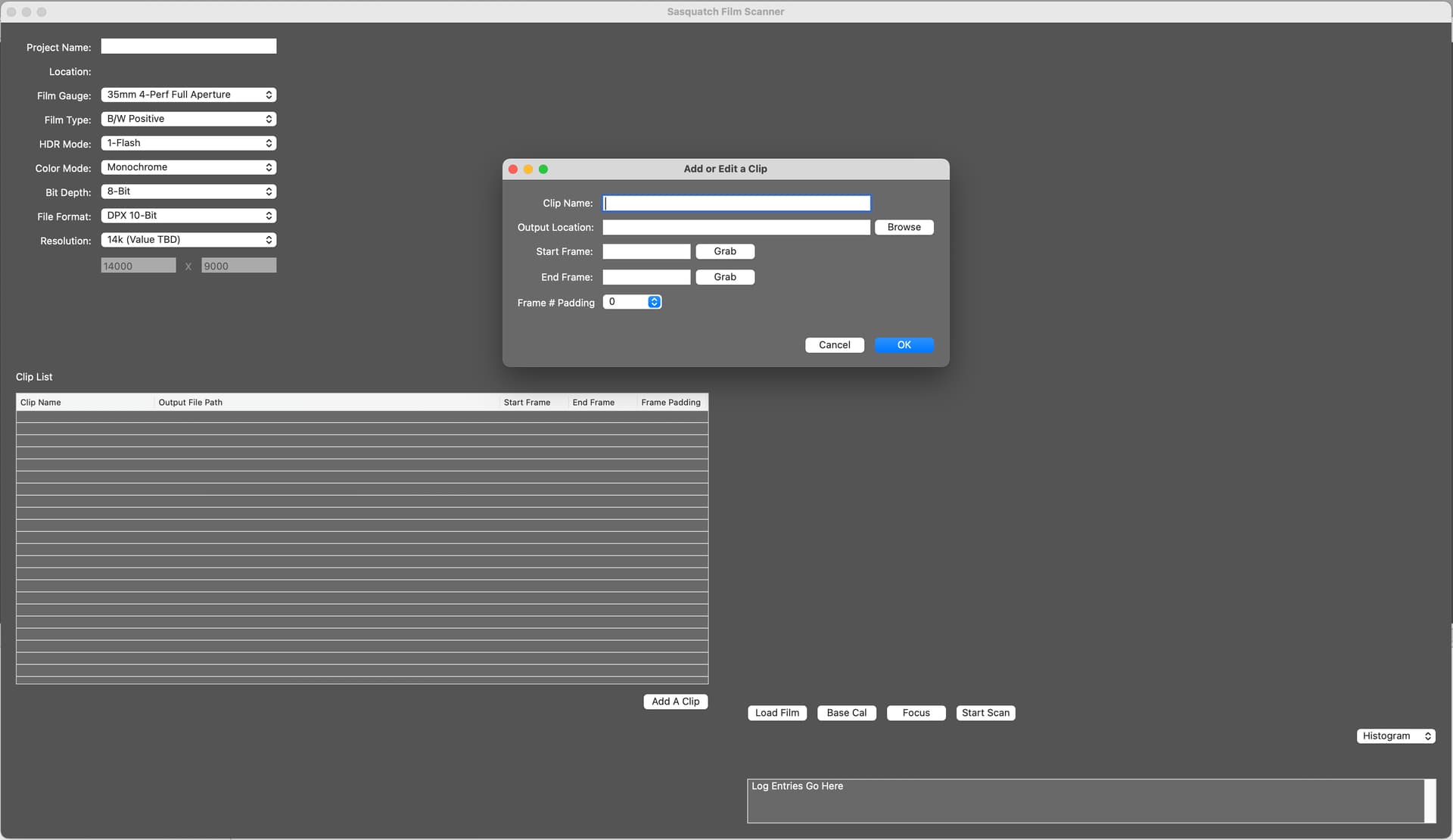
In terms of how you use this, basically it’s like a combo of the Northlight and ScanStation software, though simplified. You set up the basic Project Settings, which are global for the job at hand. Then you load the film, and you use the transport to go to in and out points. You can add a clip to the Clip List (which is basically just a batch file), by clicking on the Add A Clip button, and that opens a window where you enter the in and out points, the file name and the location. When you click ok, it adds it to the batch.

Focus will open a new window, where you will have fine control of the camera/lens positions, and we will implement an autofocus routine that will sample several postitions, detect edges, and determine the sharpest focus.

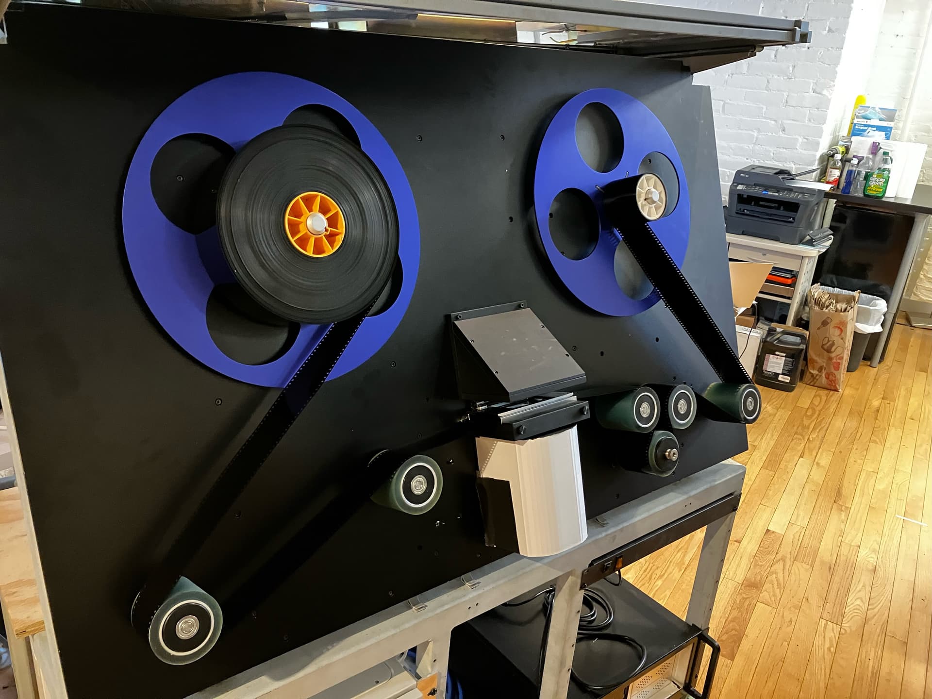
Lots more to do, and I may have to unpack a few things to do them, but this is a major milestone, and is something I’ve been wanting to get started on for months but haven’t been able to until last week.

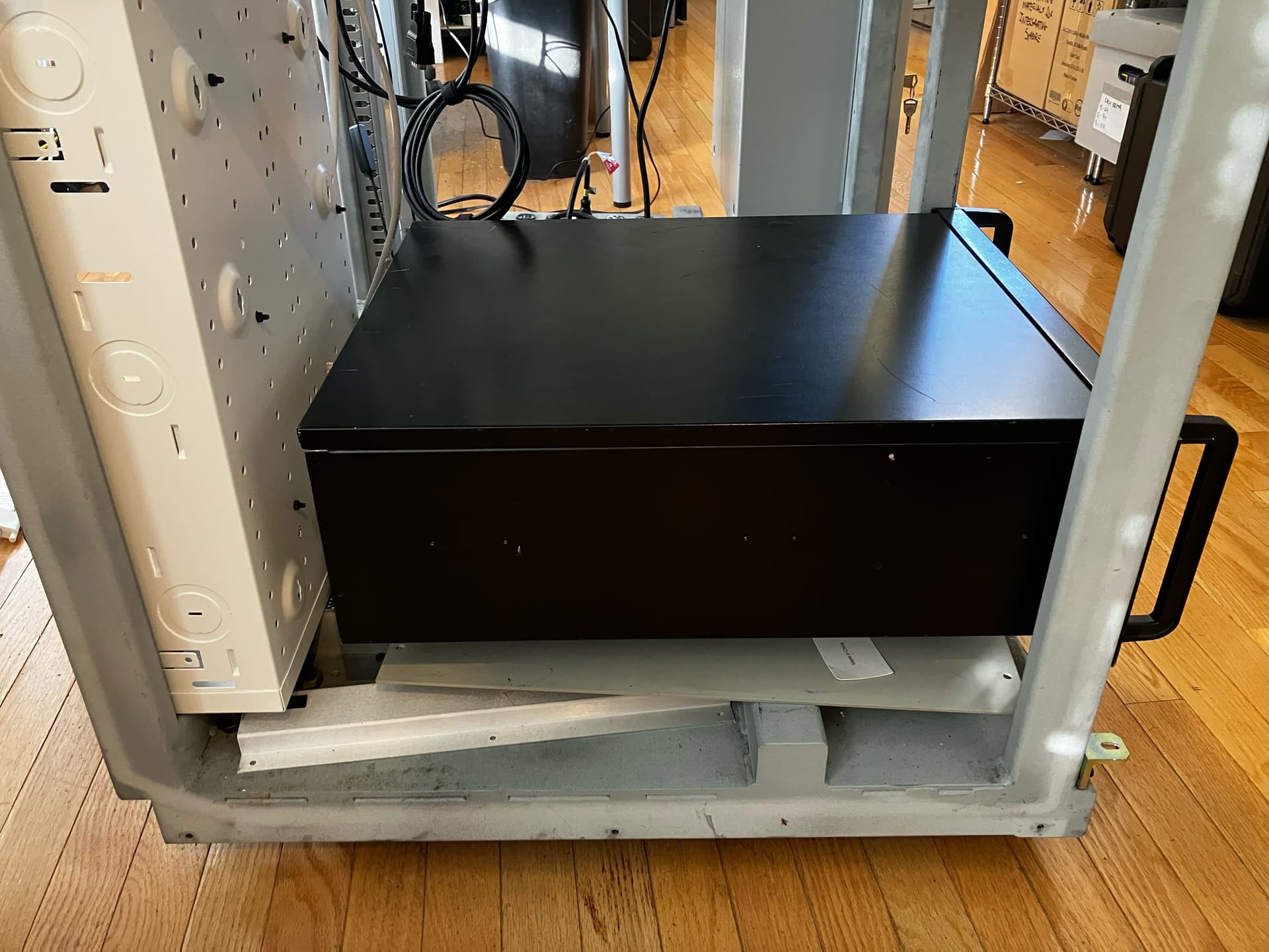
Oh, and the UI is 1920x1080, to match a monitor I picked up that looks like it’ll fit inside the old Cintel Ursa bridge on top of the scanner chassis. This may turn out to be impractical, but if it works, should look pretty cool, and keeps the whole thing fairly self-contained.

3 Likes

Some more progress, such as it is. We’re at a point where we can start testing the front end software with the motors and soon the camera, but the easiest way to do that is to move the development environment over to the PC that will be connected to the scanner itself. That machine is rack mounted, so I went ahead and put that in, only to realize the back of the PC is basically up against the back of the control box for the ClearCore and everything else. Dumb oversight.

So I spent most of today rewiring the internals of the chassis and cleaning things up. Now, the box with all the power supplies is on the same side of the machine as a the controllers, and the PC is on the other side, with plenty of room to access the back of it to, you know, plug it in.

The plan for that wood frame around the controllers is to make an adapter that lets me connect it to the original Cintel door frame that goes in there. That way we can use a plexiglass door to easily access the ClearCore and LED boards.

The plywood with the stepper drivers is also temporary. That will be aluminum, which will act as a heat sink for the drivers (way more than is necessary, but that’s fine). It will be bolted to the chassis.

Almost ready to fire this thing up and see if we can get all the pieces working together for the first time.

5 Likes

Started working on the feed and takeup motor connections. Our firmware developer has fallen ill in recent months and I didn’t know until a couple days ago. So I’m working with Teknic directly now to get these set up.

On the scanner front, the good news is that the tweaks I would need to make are all in the motor firmware through Teknic’s software, and shouldn’t require modifications to the ClearCore firmware. On the health front, our firmware guy says his doctors tell him he’s on the mend, so hopefully he’ll be able to get back in here soon to fine tune this once I get all the parts up and running.

Pre-autotune warnings:

not nearly as loud as they say though:

These motors are very cool. Basically it’s learning the limitations of the system and creating a profile embedded in the motor’s firmware. That can then be loaded and tweaked in software as I get film loaded up between the two motors.

1 Like

This is a still image, not a video. Because the film isn’t moving. Which is the point.

What you see is the feed and tension motors working on the actual scanner for the first time. Much dialing in to do to get the tension where I want it, but the film doesn’t move. Sat and watched it for 20 minutes, and there’s no creeping, even with the capstan disabled (so it’s basically just another roller right now). That’s good, and is the point of using these motors in torque mode. The next thing I need to do is gradually increase the torque on them, on the motor firmware side, until we get to a tension level we’re happy with. Once we’ve got that set up, it’s on to the capstan to start pushing and pulling the film back and forth.

2 Likes

Great progress on the machine! Do you have tension sensors to regulate tension as the roll unspools onto the next?

1 Like

Thanks. And Nope. No Need.

Once we get the motors dialed in so that they hold the film in place at the tension we want, they handle the job of maintaining that tension. the motors are configured to simply stop after 50ms if there’s no tension, and send a fault message to that effect. Basically there’s no way they could spin wild or something like that.

These also have a function Teknic calls “HLFB” (High Level FeedBack), which sends data back to the ClearCore controller about how much torque is currently being applied to the film. You specify the max torque the motor is allowed to apply in the setup software (as a percentage of the max torque of the motor itself).

To the system that lower maximum is now the effective maximum it could apply to the film. But then you can specify a further reduction to that. I don’t believe our firmware guy has implemented software control of that yet, but we should be able read the torque applied and also reduce it without having to go into the motor setup app. So a film that requires extra gentle handling, we should be able to deal with from the scanner front-end application.

Here is a video I’ve sent to Teknic to get some advice on how to balance the two motors. Right now the right side is pulling a bit more than the left, but you can see that after about a minute, they balance out and the film is simply held in place. This is maintained throughout the reel. So we just need to find the right mix of tensions for the two motors so they’re in balance at all times: Engage motors - YouTube

1 Like

That’s very interesting and amazing at the same time. I should prob take a closer look to the tekniks.

On my machine using the oDrive the tension was held perfectly between the reels without tension sensors and I thought everything was good because I was testing with the same roll all the time.

It was not a big roll, maybe 300 feet. But when I started using different roll sizes and unspooling, the tension was changing at the film gate which is obviously expected. Larger roll had less tension at beginning and the tension increased as the roll unspooled on the next.

So I added tension sensors on feed and take-up sides and the software keeps tension at film gate based on the torque baseline value set in firmware. Without tension management it wasn’t working well for regular playback speed to high rate fast forward to rewind, or pause to fast forward etc…

Now if the tekniks do that on their own without sensors I will have to seriously consider swapping oDrive to them, the tension is working good at the moment here in all modes but I would LOVE a less complex system and software :slight_smile:

This is what they have told us they will do. That said, we also have a third motor in the mix, the capstan. The issue you see in the video above would go away if the capstan motor was in its engaged state because so much of the film has purchase on that roller. basically, it won’t slip unless you put an unreasonable amount of pull on the film. So it’s kind of about finding the right balance, which I’m working on this week. I don’t expect it to be 100% holding on its own at the extreme ends, because the capstan will make sure it’s not moving one way or another. But my goal is to get it as close to a complete hold as we can, to put minimal strain on the film at the capstan, which is locked in position except when in motion.

If you just had the feed and takeup motors, I don’t think the system would work. That is, my guess is that to some degree, the capstan in the middle is required just to make sure there’s no rolling when one reel is mostly unwound and you want the film to stay in position.

The cool factor comes at a price. Granted, we’re using monster-sized motors for this because 2000’ of 70mm is really heavy, but you’re looking at a decent amount more money for the teknic setup than the o-drive, I bet.