Simple Super-8 Sprocket Registration

@matthewepler suggested that I describe a simple frame registration algorithm I am using for my Super-8 film scanner. So here we go.

This is a registration algorithm which is designed to try to register within a few pixels deviation. So it is not a pixel-perfect registration. But at least with high scan resolutions, it is within the precision of pin registration a standard camera/projector combination would have achieved in the old days. If you want perfectly stable imagery with Super-8, you need to frame-register your footage. I actually do this in a second path, once the pin-registration has achieved a somewhat stable frame.

Here’s an example of a Super-8 frame:

The goal is to locate in every scanned frame the sprocket area and align the scans accordingly.

One could approach this goal in various ways. Here’s a simple one. I include a sort of pseudo-code in Python. The first step is to cut out the relevant portion of the frame:

grafik

This is a vertical strip, as indicated in the following image by the red lines:

Flipping this strip for the sake of simplicity 90° around, this

filmgate_07

would be the cut out sub-image to further analyze.

The next step is compute the edges of this socketStrip:

grafik

We arrive at something like this:

filmgate_09

A sum in the presumed direction of the sprockets

grafik

reduces this small image into a single array. This data is smoothed again with a gaussian

grafik

to arrive at the final data for analysis. The smoothedHisto for the above frame is plotted here

Inprints_02

together with some small lines I will explain shortly.

First note the two promient peaks in the data - these peaks are actually corresponding to the edges of the sprocket we want to detect. There are some smaller peaks visible left and right of the sprocket peaks - these are the traces of the imprints of the film stock, still visible in the above cut-out frame.

The actual algorithm to detect the sprockets works with two passes and two corresponding threshold values. The first pass starts at the edges of the frame (in the plot left and right) and searches for the first data entry above the threshold. This outer threshold is indicated by the dark blue horizontal line the above plot. The outer sprocket positions found are marked by the short two top lines in yellow and bright blue.

This first search is ment to only locate the sprocket approximately. The average value between the two peaks is calculated and used as a zero reference. The center of these two positions (short dark blue line at the bottom of the plot) is used as starting point in the second pass, together with the second threshold (black horizontal line) to search for the sprocket borders. The search is done down from the small blue line towards the edge of the frame, and up from the blue line towards the other edge of the frame. Once the data value exceeds the given threshold, we have found our sprocket edges.

The detected sprocket edges are displayed in the plot above by the small red and green lines.

The algorithm can register the film as long as the sprocket holes are well-defined. It fails if the sprocket holes are heavily damaged. One could employ some heuristics at that point, but I have not implemented them.

As described, the algorithm can cope with some substantial dirt in the sprocket holes. Here’s an example of an insect in a sprocket hole

critter_01

and the corresponding detection plot/results

cirtter_02

Even with dirt and dust, the sprocket is normally located.

Finally, here is my current user interface

filmgate_06

which gives you in impression of what you might want to adapt/change for a certain film. The algorithm seems to be rather robust from my experience - most of the time, only the location of the sprocket strip has to be adjusted (Tune Pos/Width).

Working with Super-8, my source is usually color-reversal film. So non-sprocket areas are usually black. I have only one film which mimics usual 35 mm copies with clear borders. It is a film advertizing Super-8 copies of (at that time current) blockbusters. I searched for the worst scan I have from this material. It features broken sprockets (which fail), initially unfocused captures (that works), partially massive desynchronization between film movement and camera capture (works sometimes) as well as drastic changes in illumination (works mostly).

Here

registration_test2.mp4

you can download the test clip. An (untested) Python script with more detail about the implementation can also be downloaded. Have a look.

3 Likes

A suggestion: Use the same registration method for vertical but use the outer edge of the film for horizontal. Take a look at the gap between your perf and your film frame - see how it weaves back and forth? This is because in Super 8 the perfs are stamped using a 5-perf stamper that is never perfectly in parallel with the film. So you get a kind of sawtooth pattern. If you use the perf in Super 8 for registration, your perf will be perfectly placed but the picture will weave back and forth in a consistent pattern. Not all films exhibit this as much as others but it’s been a “feature” of Super 8 since 1965.

Lasergraphics modified the ScanStation scanner’s registration after we (and some other owners) worked with them to fix it after testing film shot on the Logmar pin-registered S8 camera. The jerkiness was really intense with that camera. Ironically, it’s less of an issue with cheap cameras that have narrow pulldown claws, but the better cameras seem to show off this issue more intensely. What Lasergraphics ended up doing was to use the horizontal (top/bottom) lines of the perf to do vertical stabilization, and the physical film edge (not the frame line) for horizontal. This means pulling the camera back a bit to ensure you capture both film edge and blank space in the gate. if the gate isn’t big enough, though, this won’t work.

2 Likes

@friolator - hey, that is an interesting observation. Note that this example film has probably never seen a camera. It comes from an advertizement reel for Super-8 copies of 35 mm movie films like “Star Wars” and “Jaws”, and was most probably created by an optical printer.

I have never bothered to investigate the film gates in Super-8 cameras, but the all the Super-8 projectors which I have looked at use a rather narrow pulldown claw. So only the vertical film position is defined by the claw. The horizontal film position in all projectors I looked at is defined by an appropriately designed gate, usually by some spring mechanism pressing the edges of the film against a fixed stop. I took some guidance from these investigations in the design of my 3D printed Super-8 film gate. As designed, it does not always assure a perfect horizontal scan position. But horizontal movements with that gate happen only at cuts, occasionally, and those movements are barely noticable in the final scans.

It wouldn’t matter if this is a print or camera original. the problem is that the perfs are never perfectly parallel to the edge of the film in Super 8. I’ve seen some reels that looked better than others, but unlike all other gauges, Super 8 exhibits this problem, if you use the perfs for registration. On our scanstation, when you use the film edge, you’re basically employing a virtual spring-loaded edge guide. Same effect as you describe.

With the scanstation, with Track Frame Edge turned on, the frame will be steady, but the perf will now weave back and forth in 5-frame increments, because that’s no longer being used to do the horizontal registration. Basically, you see what’s actually on the film that way.

1 Like

Well, this is an interesting discussion and it prompted me to look again at some old hardware.

Here’s the film gate of my old Super-8 camera:

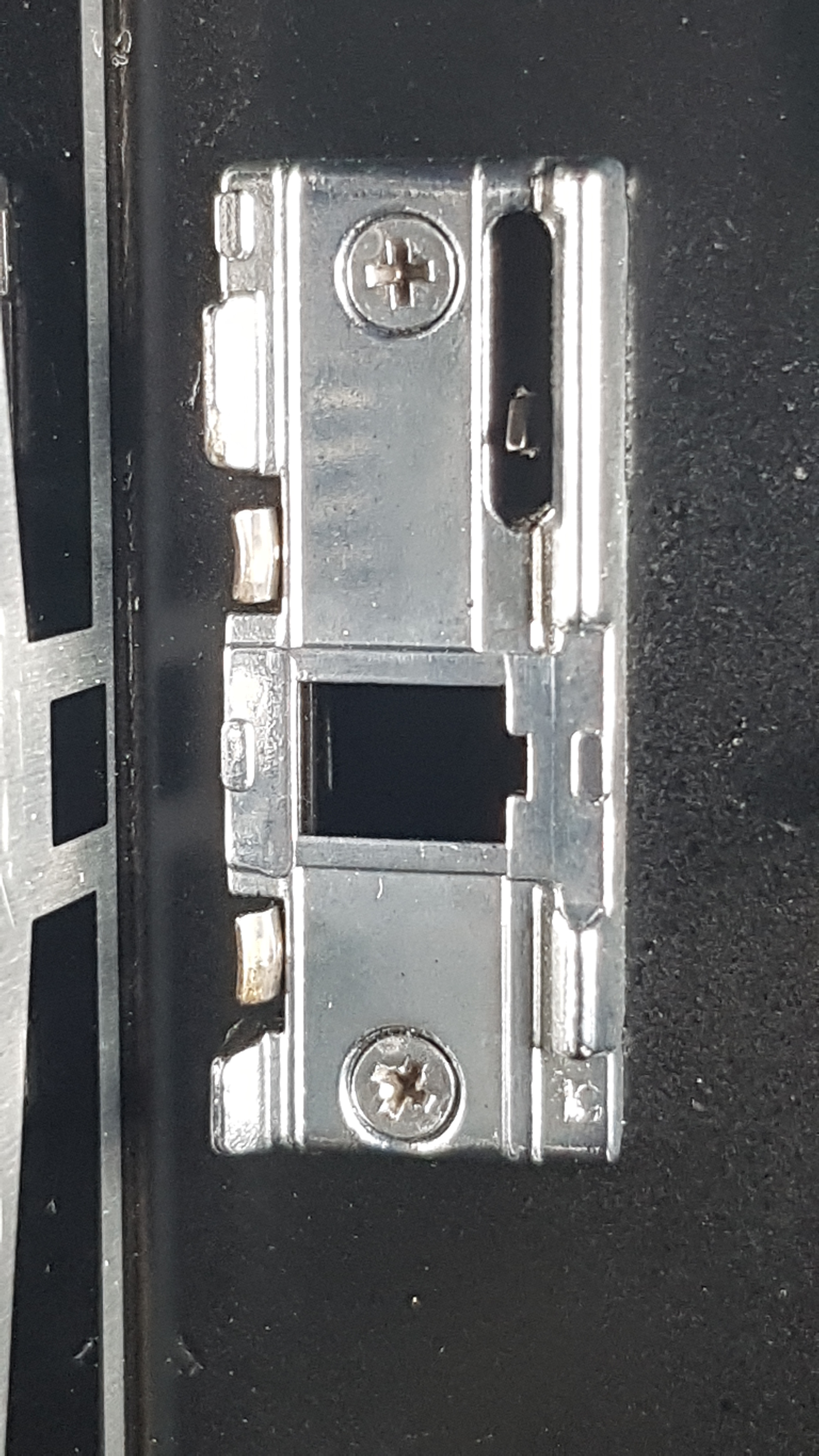
Clearly, the claw of the camera did not much in fixing the horizontal position of the frame. It’s way too small for that purpose. (For comparision, here are some Super-8 dimensions I collected over time _Super 8 Format with Sound 3.pdf (93.6 KB) ).

The claw of a Super-8 camera only defines the vertical position of the frame - but, as you can see, with a two frame distance. So the sprocket hole just neigbouring the scanned frame is not the perfect candidate for frame registration.

Now, the horizontal frame position is defined in this camera gate mechanically only with fixed barriers on the right side of the film channel, and with the help of two tiny springs on the left side: the two tiny tongues visible just below and above to the film gate.

Basically the same trick is done with all the old projectors I had a look at. These projectors use always a construction similar to the above discussed camera gate.

There is a difference however. Some projectors use exactly the construction described above, where the fixed barriers are at the side where the sprocket holes are. Some projectors swap this arrangement. The fixed barriers are opposite to the sprocket holes, while the springs are on the side where the sprocket holes are.

Which one is better? Actually the later, because cuts were done with Super-8 film mostly with adhesive tape. This tape was wrapped around the edge where the sprockets are, 2 or 4 frames long. During these 2 or 4 frames, the sprocket edge is sligthly wider than the Super-8 specs define, leading to a small drift of the frame position during cuts. Projectors with fixed barriers on the side opposite to the sprocket holes do not show such a drift.

In order for the barrier/spring mechanism to do its work, one needs the claw to be smaller than the sprocket, to leave headroom for some sideway movement. Here’s an image

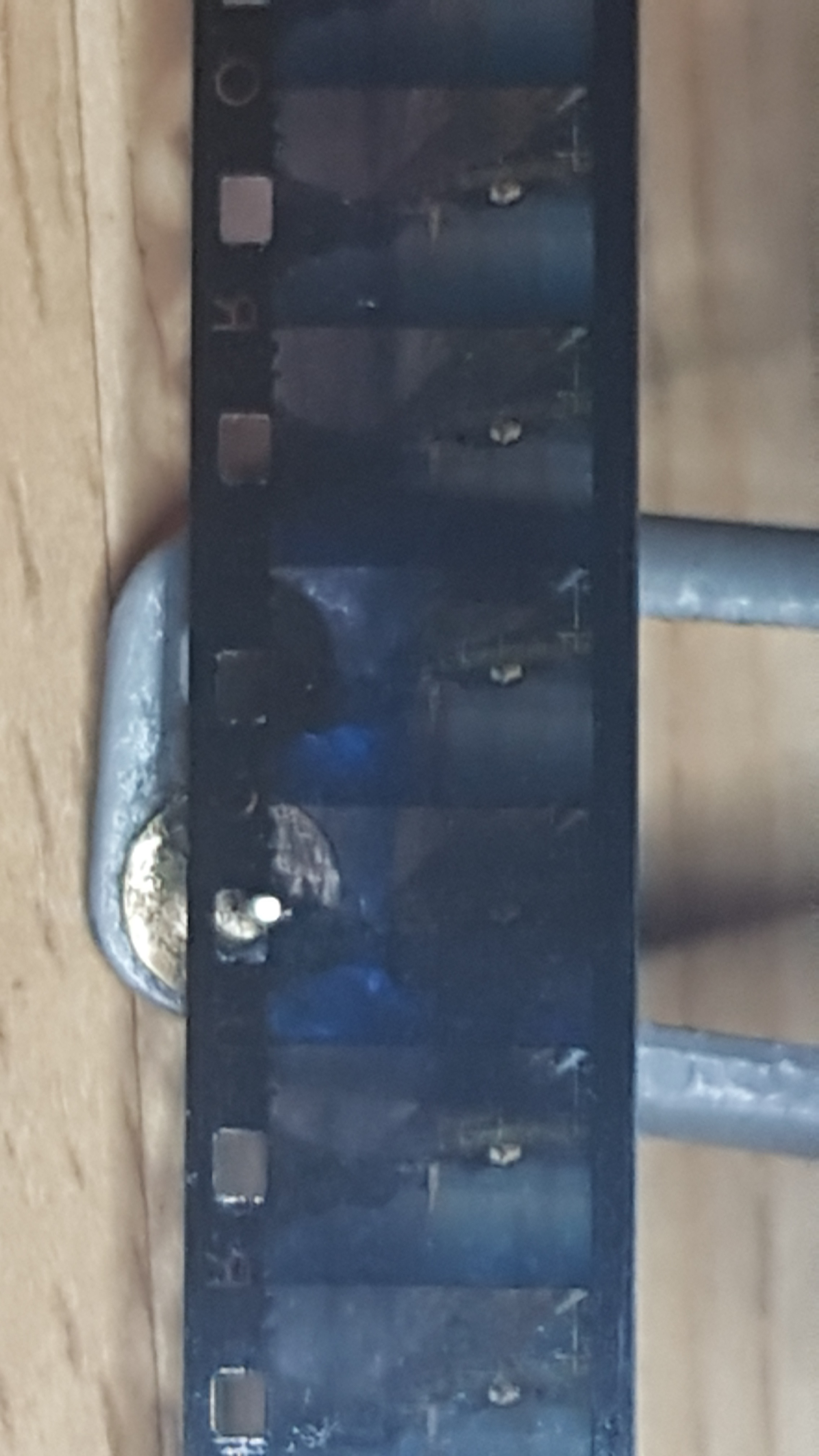
of a projector claw, together with a short Super-8 strip for comparision. Note how small it is in comparision with the sprocket hole. Again, as with normal Super-8 cameras, in Super-8 projectors the claw as well as the sprocket have no business in defining the horizontal frame position.

1 Like

Just adding this for reference.

Here’s how a cut with adhesive tape of a Super-8 film typically looks like:

tapedCut

As described above, it covers/wraps around the edge where the sprockets are, not the opposite edge. So you might want to use the edge opposite from the sprockets for horizontal frame reference.

… some update with respect to the applicability of the above described algorithm to 16 mm footage.

I implemented @friolator’s idea of applying the algorithm described above in the horizontal direction as well. @matthewepler supplied me with 16 mm material and many helpful comments - thanks to both of you!

The raw scans of Matthew can be watched here( raw 16mm source). The scans display horizontal as well as vertical jitter.

Extending the idea described above to the rightmost vertical edge of the detected sprocket, and supplying a suitable region-of-interest, the following result was obtained (16mm sprocket stabilized).

The sprocket visible in the lower left corner of the frame is the single sprocket which was used to register the frames. Note that the sprocket visible in the top left corner, which was not used in this stabilization, stays rather fixed as well.

If you look closely, the frame still displays some tiny jitter. This is most probably due to the deficiancies of the optical printer used. Indeed, if you look at the terminator between the frames, you will notice that the vertical width of that terminator changes over time - usually a clear indication that the alignment between sprocket and film frame is not perfect.

Furthermore, if you frame-stabilize this footage, you will see that the sprocket holes start dancing around a little bit. A further indication that frame-sprocket registration is not perfect in this test case.

16 mm material as well as 35 mm tend to have a lot of lettering between the sprockets - this is somewhat a challenge for the simple algorithm described. An appropriate ROI helps here.

I also had a look at 35 mm material, but this poses some additional challenges, as the sprockets are much closer together and it is not easy to detect which is the correct sprocket to lock onto. For a general solution, a more advanced algorithm might be needed.

1 Like

What an improvement! Thanks for sharing your work with us. I think it will come in handy for many folks. Is the improved code at the same link as above, @cpixip?

cpixip
Great job! Before stabilization, what is the algorithm for increasing and cropping the frame?
Or were you given the original frames of the scan?

@dan74: Matthew shared his original scans. They are large (so no special magic in order to increase image resolution was required).

However, due to bandwidth constraints I have here at home, I opted to post only scaled down versions of the clip before and after stabilization.

With respect to the processing pipeline: before the sprocket registrations, the input images were rotated so that the film strip was vertically oriented. The design of the sprocket algorithm requires this.

After the sprocket registration, the images were cropped and scaled down. Some slight gamma-adjustments were also made, as well as decolorisation of the original RGB-data. That’s all.

@matthewepler: I will post the new code as soon as I can. The code is currently in a state which might be called “spagetti-code” at best. I want to clean that up and introduce appropriate comments before sharing.

The code for the sprocket detection and alignment algorithm can now be downloaded from my github repository

GitHub sprocket-detection

There are also a few example images in the repository. Have fun :slightly_smiling_face:

2 Likes

Thank you for sharing this algorithm and even the code, cpixip!
Beside what Perry already said about horizontal registration, one other detail is important though for perfect registration of Super 8 film: The offset of the sprocket hole used by the claw vs. the one next to the frame. It might sound counterintuitive, but it matters, since the S8 spec allows (and often has) quite some tolerances in the sprocket hole’s distance to each other. This tolerance doesn’t matter as long as camera and projector use the same (offset) sprocket hole — and that’s why the ideal scanner should do the same.

It’s annoying, since the offset sprocket hole isn’t in sight of the scanning camera, so not a lot you can do in software to compensate…

@peaceman - that’s an interesting point you mentioned, the sprocket-“exposed frame” distance.

In fact, when I was designing my film scanner, at one point in time I was considering scanning not only the frame in question, but all neighbouring frames and sprocket holes as well. To handle exactly the possible jitter which would be introduced by using not the correct sprocket hole for registration.

I decided against that option because it would have wasted too much precious pixel space, scanning three frames instead of a single one.

One question here: the Super-8 cameras I checked always use a two-sprocket distance between claw and exposed frame (see for example the image of a camera gate I posted above). I am not aware of any camera with a different distance between sprocket hole and exposed frame, at least not, if the standard Super-8 cartridge is used. Do you have any examples for a different sprocket-frame distance?

The reason I am asking is that I am entertaining an idea to try to actually implement a two-sprocket distance registration algorithm by using only a standard sequence of frames, taken with a small overscan (I’ve been implementing image processing algorithms for nearly 40 years, it would be a fun project if time permits and I think it’s doable).

Some further remarks: as I discovered already in the 70ths, such an effort is not really worth for my own material: I tested at that time my camera (a “Revue”-camera) by simply double-exposing a fixed grid, only to see the two grids dancing wildly against each others in the projection.

As most of my material is also free-hand, not tripod material, most of the time I tend to employ a frame-based image stabilization in post production anyway.

A sprocket registration code similar to the one published above is actually used in my film scanner to drive the stepper in a feedback loop, for centering the frames in the camera window during scanning.

I think all Super 8 cartridge cameras (have to) use the same -2 offset. The plastic piece in the cartridge (that, together with the camera’s gate forms a film channel) does not allow an other offset.

Some DS8 cameras though use a different offset, especially those that were modified Double 8 cameras. OTOH, DS8 stock either seems to have been perforated with higher precision (is different puncher tool is used, 1-4-5-8 instead of 1-3-5-7 for Super 8) or the DS8 camera’s tea pressure plate improved registration to a degree that the offset didn’t matter. On Super 8, it definitley matters. (Especially when using my Logmar, which is pin-registered)

I love the idea of using temporal/spatial signal to register using the correct sprocket hole even though just doing a little overscan. Did I get you right that that is what you have in mind? Kind of “remember” where the second- last sprocket hole appeared related to the frame boundaries?

Well, I was actually thinking more along the path(s) of a traditional photogrammetry task. Since nearly a century, airplanes, later satellites and drones, have taken sligthly overlapping images of the ground below which were later combined into a complete image strip of the land covered. There is a certain similarity between this task and the task of reconstructing a film strip. In this case, I really mean a film strip, one large image representing the whole film in question, not a traditional set of single frame captures.

From such a single, large film strip, specific frames could be easily extracted, as well as other optical information, for example the position of the second sprocket after a certain frame or an optical sound track. The good thing: no mechanical precision involved here at all - its all computational algorithms.

I am currently looking into laser-based sprocket registration and wanted to use the same sprocket hole that the camera uses in order to achieve better out-of-the-box stabilisation. Now, it seems to be established, that on Super 8 this is the sprocket hole at an offset of -2 from the visible frame. But would you happen to know what it is on Standard 8 cameras? Is it possibly not as uniform in the world of Standard 8?

I only have a Bolex dual-gauge projector for reference, where it seems exactly the opposite offset is used for Standard 8 (+2 frames from the visible frame).