I can do some here. I don’t have any fancy testing equipment. Any suggestions beyond reading values out of a serial port?
Perhaps we should start a document that lists the light source, type of sensor, etc. so we have a way to keep track of the test variables and results. If you guys and gals are game, I can start that up.
Also, what should we be testing? Types of lights/sensors…I have the common off-the-shelf LEDs and light sensors. But that’s it for right now.
Black and white film blocks most of the IR spectrum, different colour stocks block from almost none to around 30% in various areas of the frequency.
Other manufacturers have had better results with Blue LEDs on the sprocket area, and placing them before the camera sensor so that there is no light bleed.
If you are going slow (1-3fps) almost any sensor will work, once you get up to speed it becomes a problem. It might be worth playing with polarisers to see what effect they have - anything that might magnify the difference between the clear stock and empty space is worth investigating. However remember that every stock type has different properties.
BTW, the Muller uses the same triggered light source for capturing that I have outlined in other posts designed by Frank Vine.
Hi I’m new to this forum. I’ve be working on an 8mm project. I have used the
mechanism of a film editor, and modified it by removing the four sided prism. I then fitted a four blade shutter and photo-interrupter to give the trigger signal.Whilst this did work,it produced a lot of bounce. The bounce had a beat of four. It had to be the shutter. So to test the theory I made a thin metal finger that drops in and out of the sprocket holes. An electrical connection is made between the metal gate and the finger,providing the registration signal. Here is a youtube link. https://www.youtube.com/user/whoam42a1?feature=hovercard
It’s a very crude method, but it works very well. Its an ongoing project that need more work.
Hey, I had a friend do a UV-Vis-IR absorbance spectral analysis on some film. I had her do three samples, one Polyester and two acetate, labeled “Scrappy” and “Black” (I have no access to nitrate and I doubt too many of us are interested in handling it). Something that might be of interest to us here is that they both fluoresce at ~300nm. Check out the UV tab on this spreadsheet:
Instead of an expensive laser, it might be possible to shine a cheap UV LED to fluoresce the film and look with a visible spectrum camera at where the sprocket holes are.
input is 5v
Photo Interrupter is a OPB815WZ
and i use a Transistor P2N2222A
and i use a 10kOhm trimmer potentiometer so i can fine tune the sensitivity = output volt to the camera to trigger the camera to take a photo
and i use one 250 to 500 ohm resistor on the Emitter side
Looks great! I’m thrilled to see someone building test rigs and trying out new sensors. It really makes me happy. You have a great setup!
I have done a few experiments myself with the photo-interrupter and can share some of my findings. Please don’t read these as criticisms, rather just sharing what I experienced in my own trials.
it works great until you have clear film. The light source in the interrupter can be seen through clear celluloid very easily and renders the sensor unreliable. But if you’re sticking to black celluloid, it’s a great option!
Due to my findings with #1, I tried a reflective sensor instead and it worked well.
Although the reflective sensor worked better, I still had trouble if the film’s perfs were damaged. I’ve considered trying to use multiple sensors and averaging the values so that a missing perf does not throw off the machine completely but have no implemented it yet. Instead, I’m going to try using computer vision to detect frames, thereby bypassing the need for additional circuitry.
@VitalSparks has propsed an interesting system that could work with just one sensor (reflective/interrupter, etc). It relies on a a concept called Phase-Locked Loops. It would average the rate of perfs detected and use that as a “pulse” signal to the machine to capture frames. It’s a great idea and I look forward to trying it with the reflection sensor some day soon.
@MikeThibault this is awesome. Did the samples include a clear celluloid base at the sprockets? And is the conclusion that UV light passes through black celluloid at levels that could work with a light-sensitive sensor?
i have one film that have clear celluloid it´s a SMPTE 32 test film Rodenstock APO_Rodagon D 75mm f4.0_TEST | Mattias Norberg | Flickr and photo interrupter did not work so good it allmoust did work good maby if i do eaven smaller hole for the photo interrupter to look thru i have now a 0.8mm hole you can see here and some more photos of the sensor
here i have photo how i did connect the photo interrupter
hmm i have try little with rotary encoder to find the sprocket holes on the film and it did work but not as good as photo interrupter
the rotary encoder i have is a Bourns EMS22D51-B28-LS5 i have some other brand to like this one ( https://www.youtube.com/watch?v=QE4IQlwOgiA ) but it did not work as good as Bourns EMS22D51-B28-LS5
here is my main setup i use it looks like this i use a hall sensor and a magnet and i run the film 2 times thru the projector low and high exposure and merge them with avisynth
and here you can see some HDR captures i have done i run the film two times low and high exposure and join them with Avisynth
Actually I mean that the film should glow, like fluorescent dye under a black light. Shouldn’t matter whether it’s black or clear, so I imagine for most of the time the UV LED would be on, while a glowing outline of the film (with black edges and sprocket holes) is seen by the sensor, then when the next frame reaches the exact position, the UV LED would switch off while a separate visible spectrum LED would flash for taking the actual frame image. Then repeat the process for each frame. Haven’t tested it myself though.
Starting to look into different ways for transport/sprocket detection and came across this patent. DE102009032943B4 - Flash film scanner with optical perforation detection - Google Patents
In the prior art, there are a few interesting methods for detecting including light reflection or light through (as the patent).
Was wondering if something like a capacitive or RF sensor would work. I have to confess I do not have the RF expertise to make something that small (looking to do it for Super 8 film). In any case, for frame-by-frame scanners, I think a good stepper driver like the TMC2208 with microsteps would provide the accuracy to eliminate the light sensor on the patent, and move the film off the stepper. Thoughts?
That’s really cool! It is convincing me to give up on the pinhole I’m using with my optical detector for a condenser lens in front of the laser
From elsewhere in the forum I remember seeing some versions of sprocket detection that worked by completing a circuit through the open sprocket hole, but that could potentially be disrupted by errant tape or defects in the sprocket hole.
How were you imagining an RF sensor setup might work? I don’t know how much film may attenuate RF or if it could have the spatial resolution to measure a sprocket hole, but I may not be imagining it right.
Imagining is a good way to describe it John. A caveat, I am looking for a method for frame by frame detection, so capacitive or rf detectors may have another degree of complexity if one is looking for scanning at real time film speed. Having said that, I think is worth looking at this with fresh ideas, and once these are well understood in the slow and forgiving frame-by-frame can be improved for faster moving film.
What I was imagining was using the film as a dielectric, and sensing the passing of the sprocket hole as the absence of the dielectric. One way (but I have the feeling it will be a slow sensor) may be capacitive sensing. My guess is the problem would be (for Super 8) that the sprocket hole is very small, limiting the surface that would change when film is not absence, and increasing the difficulty of detection. One can use the physical capacitor created by two very small plates on either side of the film to slightly vary the frequency of an oscillator and detect the changes in frequency as variations in film density. For larger film like 35 mm, the dimensions may actually work, I am concerned that for super 8 sprockets the variations will be hard to detect.
The RF ‘idea’ came from what walabot technology is doing for RF sensing… but RF is not my strong area of electronics.
I would think another alternative with laser would be measuring the reflection on the surface of the film, and detect the hole when the reflection is missing.
This is a great find! Thanks so much for posting. I’m passing it along to the engineers at Brooklyn Research. It may help us figure out a good solution for frame detection.
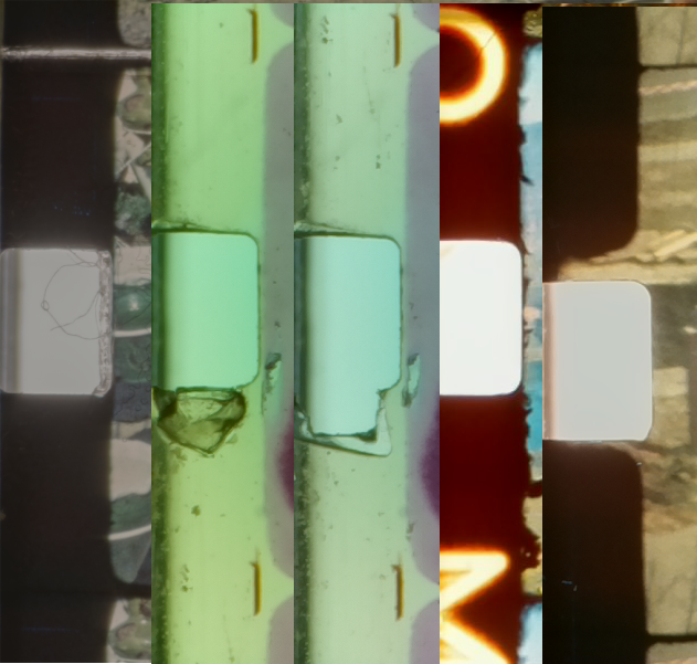
The left-most sprocket shows something which you encounter very often with old Super-8 material: dust. In this case, if you look closely, the dust accumulated around a splice - Super-8 movies were often spliced together with adhesive pads. However, even if you clean film before scanning, you will encounter sprocket holes which have some sort of dust accumulated. Right to this is a damaged sprocket. The sprocket itself is still clearly defined, but already somewhat larger than the norm. Moving further to the right, the next sprocket (from the same stock) is even more damaged. Clearly, a registration using only the upper edge of the sprocket would work, but the lower edge is certainly torn out and not usable. Both examples feature also another challenge: the film material surrounding the sprockets is nearly as transparent as the sprockets themselves. That makes it harder for optical based methods to detect the sprockets. The next sprocket example shows also a challenge one encounters with Super-8 stock. Most material has some more or less transparent imprints between the sprockets - this also is able to fool certain sprocket detection mechanisms. The last sprocket example shows another challenge I encountered: the film gate of the camera used is extending into the sprocket area. In the example given, the edge of the sprocket is still clearly defined. But if this part of the film frame becomes very bright or even overexposed, the boundary of the sprocket might visually “disappear”.
Maybe it is possible to collect some further examples of sprockets, preferably also from other formats, in order to develop a general approach? From my experience, I think some suitably tuned image processing algorithm might outperform any other means.
… here’s another, rather usual example I encounter with Super-8 film. This is how this might have happened, typically: during projection, something happens, so film is torn apart. One or two of the damaged frames are cut off and the rest of the film is spliced together again with adhesive pads.
These are definitely examples I see in my own films - knowing that the film stock would be transparent in certain areas around the sprocket holes I decided to angle the laser & detector pair instead of keeping them normal to the film path. This allows me to tune the sensitivity of the detector to fall within the range of the amount of light transmitted when no film is present (sprocket hole) and when transparent film is present and some light is reflected away (clear or picture area around the sprocket hole).
Has anyone experimented with optical flow sensors (aka mouse sensors)?
I started thinking about sensing the reflection of the film with a laser diode for picking the sprocket, basically where there is no film (sprocket hole) the laser will not bounce from the film, and it would not count. But then it came a couple of examples of using essentially a mouse as a linear sensor. Wonder if instead of the mouse assembly (sensor + led) one would use the (sensor + laser) to pick up the reflection on the film surface. Food for thought. Here is an example Using a computer mouse as linear sensor - YouTube
Or for that matter using the sensor to accurately measure position from one of the rollers (similar to the patent above).