In order to simplify my responses I’ll answer them inline
From matthewepler
February 11
Great thoughts, @Charles! Thanks for sharing. I recall @VitalSparks bringing up the idea of a phase-locked loop for timing or the camera trigger some years back. I was never able to test it and would love to see someone implement it on a little film loop and share the results.
It’d been years since I gave away my 16mm projector and all I have now is silent home movie 8mm. But I’m good at using LTspice so I might throw together a sim for the circuit that should include most of the required characteristics of a closed loop using the laser pen sprocket detection.
The other facet I definitely want to try is sim the whole physical reel-to-reel loop plus capstan. It’s a much faster breadboarding technique and I can check the servo loop stability requirements.
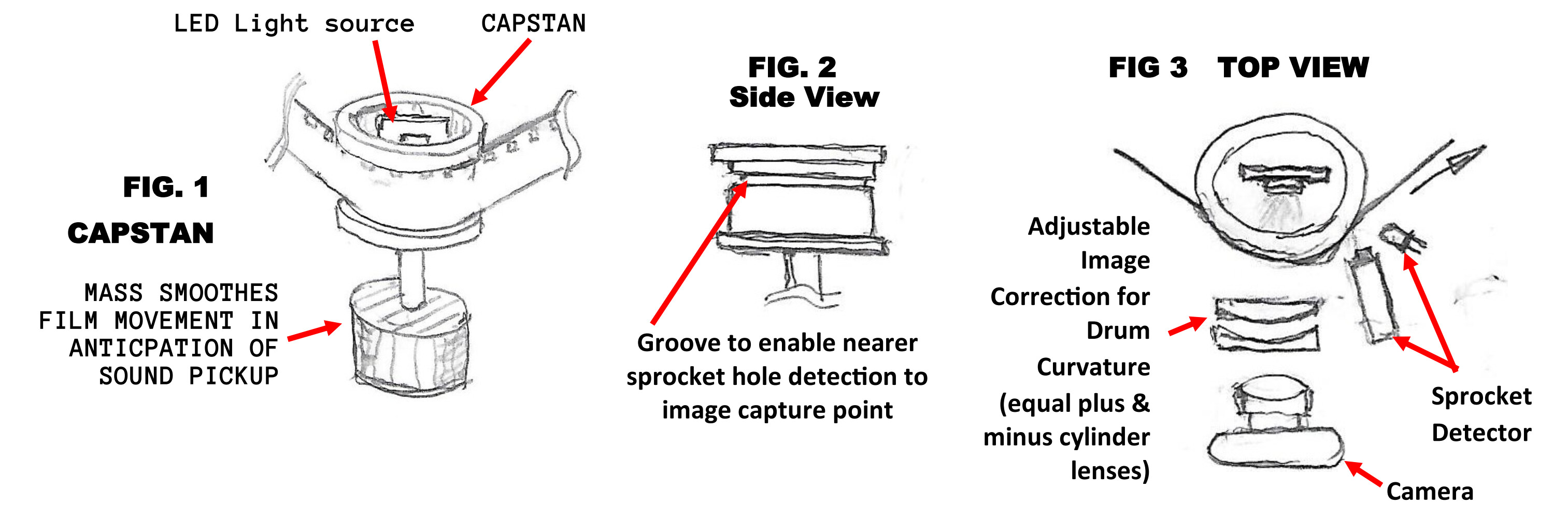
The clear capstan idea is very interesting and I like the visual aid you provided with the soda cans. I wonder, however, if proper diffusion of the light source can be achieved at that distance. Perhaps if you closed the top of the capstan and filled the middle with light from “behind,” in-line with the axle?
That’s an interesting thought. What led me to the cup design idea was the concern with two items:
Light loss through the opal/diffuse solid would become very high with the minimum 2.5’ dia. And I’m grateful for Grace’s comment of the required flash light level feeds into that decision, too. (Discussed more a bit further down.)
I didn’t like the thought of a clear capstan as I was worried about any dirt, hair, scratches, etc that would be on the surface would be imaged along with the desired film image since the whole idea is to control the image plane with the curved surface of the capstan.
It would be interesting to see a test of that too, perhaps printing the roller with white filament on a 3D printer. Do you have access to one?
I do not. I do have a lathe and mill coupled with minimal machinist experience as my main background is electronics design and software programming.
If not I could print a roller and send one to you.
I would be wary of a 3-D printer part for this particular application for several reasons:
As mentioned above the opacity of material. Are there any mildly or even transparent 3-D printing plastics? Too opaque will be a problem
And even if such plastics exist they will surely exhibit density/refractive index changes throughout the printed part that would lead to light focusing variations onto the film image/optic path into the camera.
I will order a green light laser and try your reflective idea. I’ve gotten some tips recently from other folks that confirm the need to focus the beam, either by lens or pinhole. I also did a test with an off-the-shelf component that did this very well, but whose beam was not small enough to work on 8mm film.
I just bought mine for what I thought was a good price from Ebay:
www.ebay.com/itm/3-Packs-900Mile-Strong-Laser-Pointer-Pen-For-Cat-Pet-Toy-Red-Green-Blue-LED-UV/174479778832
A red, blue and green laser pen combo pack for $9.99 with free shipping from NY. So delivery was quick. You’ll be able to immediately see the differences.
I wouldn’t recommend a pinhole for this, as using a lens to focus the beam will retain the beam power and will actually result in a much smaller point. The reality is that a pinhole is likely to be in the 10 mil diameter whereas a lens should get close to the diffraction limit of around 532nm (0.020 mills). Of course the homogeneity of the beam enters into this, but the advantage is clear. Also in my first posting I was suggesting the use of a line generating lens setup for some possible improvement in the detection process. The optics will probably cost much more than the laser pen.
I hope to try a couple things to further this test:
put a pinhole cover on the off-the-shelf component
make a homemade version of the same setup, with a pinhole
make a homemade version with a focusing lens (another forums member is sending me one)
I did not know about the green led physics. I’ll have to order one of those.
And then some responses to Grace’s post.
From : vintagefilm
February 11
Wow, some very clever info here. Some questions/suggestions.
If your capstan is a large diameter, say 8 inches or so, you could reduce the distortion quite a bit. This would be similar to the DFT Scanity. But they use a line scan imager. What method would you use to cure the distortion?
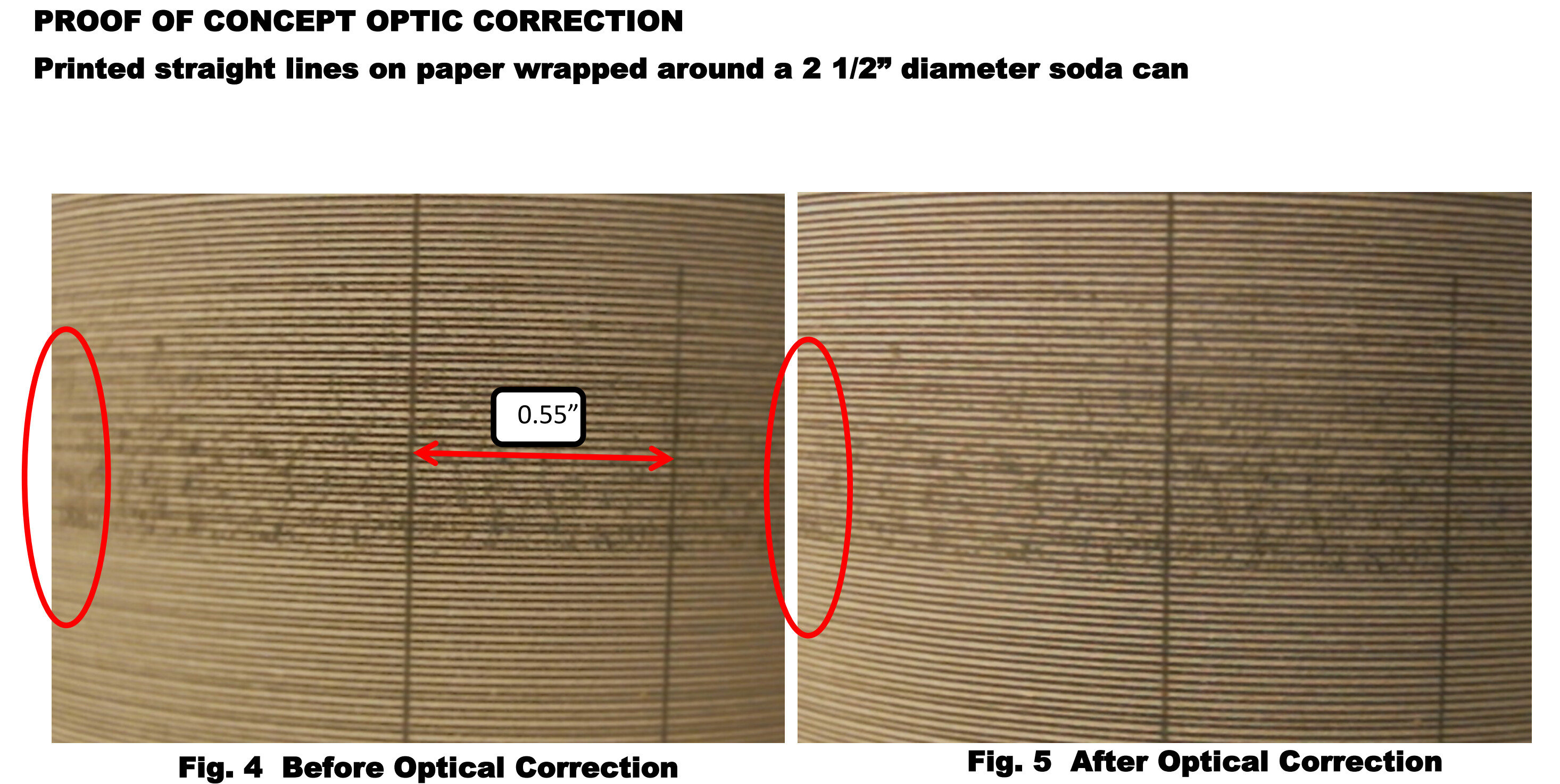
Please revisit my first post. The use of a pair of cylinder (like for astigmatism in glasses) lenses, one plus and the other minus, paired in line, by twisting one relative to the other you can go from 0 to 2x the diopter value. That is how the photos were done. One to show the loss of focus in depth of the field, and then using a pair of plus/minus lenses I adjusted to correct the field as shown in the second photo. Of course that correction is not perfect, but considering the correction here was for almost 1.25” depth change, whereas the amount of correction on a 8mm image frame of 0.130”x0.177” on a 2.5” diameter. capstan is only 0.002” depth of focus change from image center to the two sides so practically all distortion will be removed with an astigmatic lens correction as it will pretty much be 1st order correction.
Your use of a prism on the light side is interesting. Would you use separate r/g/b leds and further filter them with addition r and g and b filters?
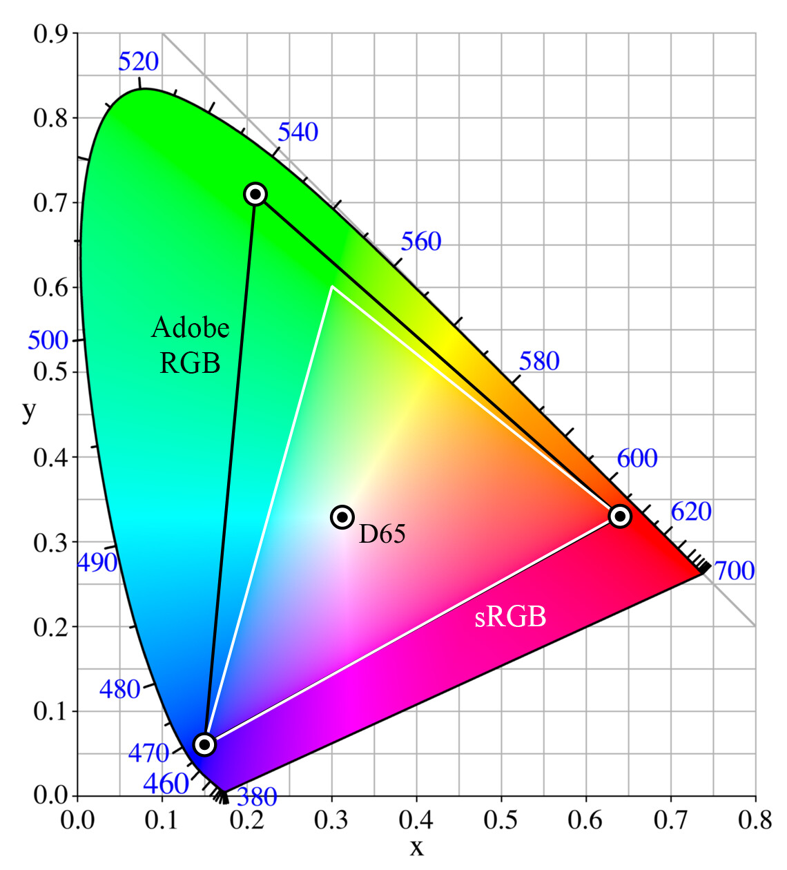
Why would I need filters? The color linewidth of red, blue and green LEDs is already narrower than the ability of most filters other than expensive dielectric versions to filter. If you don’t like the rendition vs the dye color of the film, There are some other LEDs colors available but I would suggest that since the film is dye filters, they are much wider than the LEDs. Adjust the data to fix the colorimetry of the film vs the LEDs. That’s an area I haven’t explored yet, but the film curves are weird in that they don’t use 3 peaks as we think about it, but have some bad outlying filter characteristics the film folk had to deal with. I’m sure other folks have explored this avenue extensively as I’m sure many are using 3 color LEDs to capture images.
I have several camera prism assemblies that could work for this. What about additional light processing, lenses, opal glass, etc?
I’m not sure what you mean about “camera prisms.” If you’re describing the camera lens finder versions, then no. In my research into prisms there seems to be a glut of dichroric mixer prisms – perhaps as a leftover from the LED projector market. One of those prisms can easily merge the 3 separate LED colors into one beam. Using Matthew’s idea for the solid capstan would make a very simple optical path. But using my cup capstan the only addition is the mirror or prism to redirect a beam entering the top of cup and turning at right angles to exit through the side and through the film image.
My testing agrees with your shutter speed and light speed analysis. But also you will need quite a bit more light at those speeds to expose darker/thicker film. We ran out of light using a 100w led. If each lamp was 100 watts that could work. Our next tests will use a 200 watt white, 12000K, led lamp.
At this point this is a thought experiment. I appreciate the data about LED wattage’s needed. I don’t have a ‘feel’ for it but just a gut feel calculation says a 20mW consumption LED would expose a 8mm frame in sub 100ms. So 100ms/30us = 3.3k. So I would need a 20mW x 3.3k = 67W. Hmmm. Right in line with your numbers. One comment though, is that the LED itself and are you running them in a continuous mode, because they could be much smaller as they are being flashed so the LED may only need to be a 1 to 10 W unit depending on its saturation light output to large pulse current. Do you have data like that?
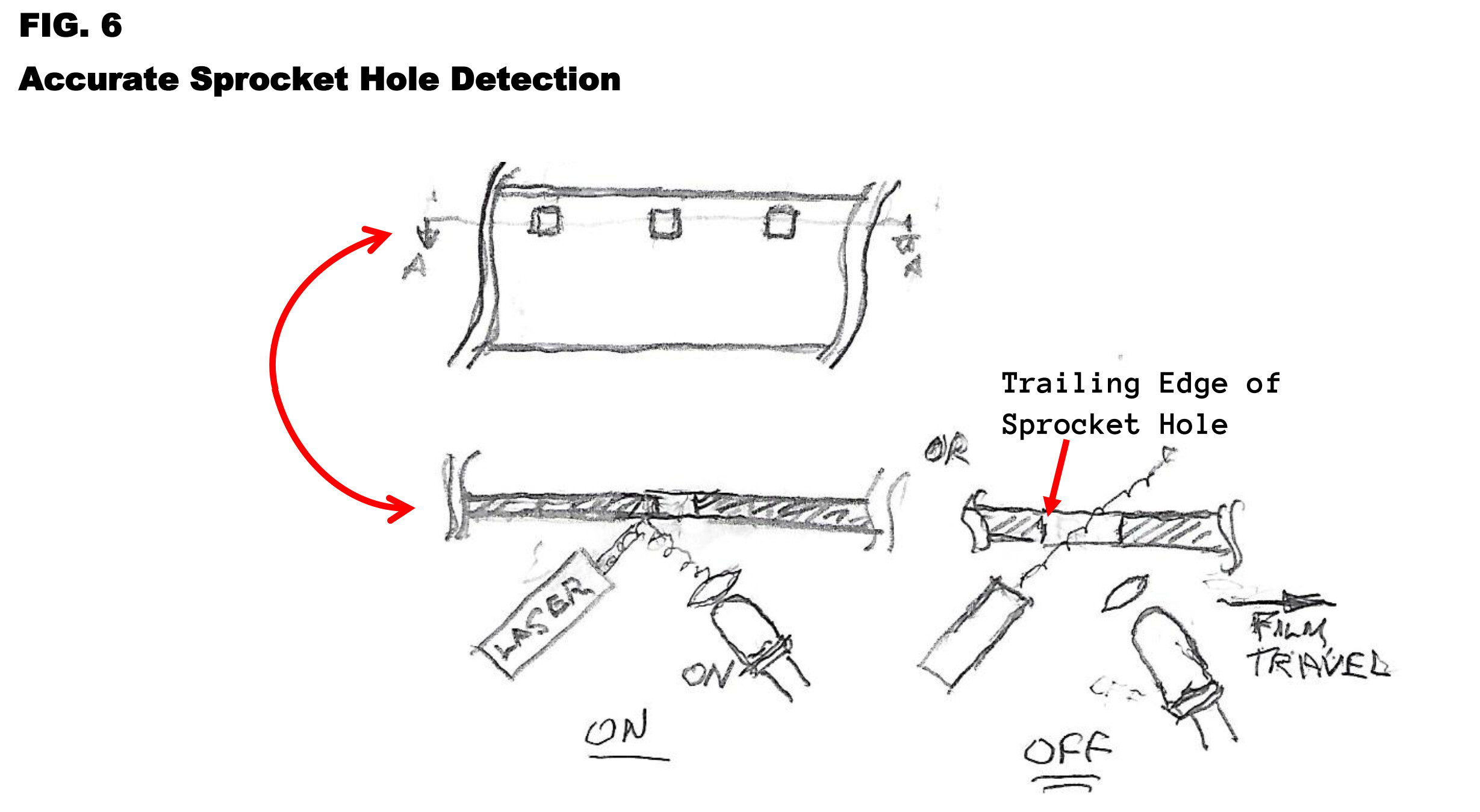
Have you tested the laser pickup sprocket detection? It sounds like it should work.
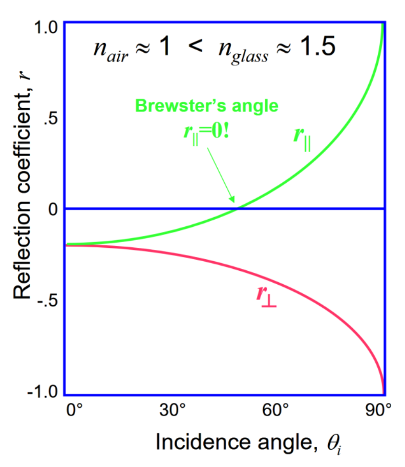
Only to the extent of the reflection technique that is clearly superior to trying to make out the sprocket holes with a beam through the film. Take any clear piece of plastic and observe the difference in trying to detect the very slight dimming by the plastic with the beam through the plastic as opposed to the total on/off quality of the reflected beam. And the polarization effect is also easily observed. Additionally the reflection method would be immune to the differences of film that has black around the sprocket hole and clear around the sprocket hole.
I think you could probably eliminate the tensions arms, but why do you want to? Cheap quadrature encoders are available, and do work well to control the reel motors. Hall sensors will work as well.
This question triggers a bit of a diatribe. I’ve done a lot of design over the years. A kind of mantra is the word elegant . Some equipment I’ve observed is elegant and some isn’t. For example. Years ago when I was much younger I was a partner in CAD/CAM business. We did a lot of punched paper tape format conversion work. The first tape reader we bought was a star-wheel reader – an abomination! Next we picked up a Ferranti 1000 cps stop-on-character reader. Oh, what a wonderous mechanism. Electromagnetic clutches engaging a grit wheel capstan pulling the tape. The noise of it stopping and starting would shake the rack cabinet it was mounted in. The tape reels were driven by multi-hundred watt pancake motors. You did not want your hands in the way if the tape broke as it used tension arms to feed back demand to those motors, I still remain in awe that we came away from that period without the loss of fingers. That unit was at least 3’ of vertical rack space and perhaps 100 pounds. Then went through a pair of upgrade improvements ending up with the GNT reader.
The purpose of a reader is to read the data from the tape and it did this exceedingly well and reliably. Small motors, one on each reel, gently moved the tape through the photocell head. No noise, gentle tape handling that never broke tape. No tension reels or devices to generate a complex path to thread. The tape just gently sped up and slowed down quietly. Total rack height about 9” and weight perhaps 5 to 10 pounds. Elegant. We also marveled at the beautiful, reliable performance of this device. I hadn’t formed the philosophy of elegant design yet, but the seeds were planted.
Subsequent years I had to work with equipment, systems, and software designed like the Ferranti. They worked after a fashion but looked like the idea started out simply, then the fixes for this and that get hung on and you have the Rube Goldberg design. I fully admit I’ve had my share of those designs, too. But I do my best to avoid that syndrome by better upfront planning, hence this design idea I posted. Discuss it and maybe it will be elegant.
To that end the only thing that tension arms bring to the design is servo stability for the reel/tape drives trying to bring up the tape start/stop speed. But that right off the top takes more power and three motors. The GNT reader only had two motors and was gentle by the elegant design step of putting in quadrature sense of the tape sprocket holes and using it to electronically clock the data into an IC FIFO. The FIFO had a digital output of half full that triggered the reel motors and so as data is pulled by the computer, the FIFO would start emptying out. When it passed the half full mark it would pull more tape. The computer stops taking data, the tape continues moving until the FIFO is more than half full. Reel motors stop and the FIFO waits for more data pull requests. Elegant. It was faster than the huge Ferranti.
So I argue that with modern small embedded computers like the Arduino or Raspberry PI, the computation required to do a similar task of gently moving film is no more difficult. The lack of need for tension sensing devices allows a very compact layout of image capture and film movement. Even the power requirements will be minimal. Talk of the 100W LEDs is not the actual average power requirement. Some 60 to 100 mW perhaps due to flashing. Even only a few W, perhaps 10-20 W total for the motors. Don’t try to accelerate instantly and the power required drops down to only the running friction of which this design has a very low amount.
This is why I don’t want to use tension arms. It’s one step away from the elegance of the main purpose, capture the film images with:
Maximum resolution
Gentle film handling
Minimum power requirement
Quiet operation.
Compact footprint
Lightweight
Simple, robust, low maintenance
So this is the way I think, obviously the goals often require tradeoffs. That’s what a designer is there for. But this is a foray into a telecine design just for the fun of it. Lord knows there’s not a large market out there! So no one is going to get rich.
One thing that has not been explored here (to my knowledge) is the need for the transport to reserve ( reverse ) easily. Will your system do this?
This is easily done but why? The reel design contemplated would not work well as a Moviola due to the already stated technique that it would not accelerate quickly – no stop on image. It is thought that the film would be started, left alone, and captured.
Having said that, it would be relatively easy to count frames as you move along and keep track of that. Stop accepting data to the computer, send a command to reverse the film to a frame number, wait for the data stream to come available again, while the transport pulls the film back past the desired point, then reverses to move forward again and start streaming data when it re-reaches the desired frame. Is this suitable?
Oh, also, Depth Of Field. More light equals more precise focusing, more DOF is better in this use case
Here I would disagree. Depth of Field is achieved by stopping down, creating the need for more light. But it is not sharper – the resolution is decreasing for an overall illusion of sharpness, but not really due to the Airy disc phenomenon. See: Airy disk - Wikipedia If you look at applications requiring good edge resolution like photomasks, printing plates, etc. the lenses are actually larger (and a lot more expensive) for just this reason. That is the problem they’re fighting constantly.
By using a curved capstan with a very controlled image plane, I argue that this design will give a more constant, better resolution taking full advantage of the better lenses that some builders will use on a larger format camera. If they use these larger format cameras for 8mm capture I’m not convinced that it’s not overkill as the image in the film probably doesn’t support it. But the only thing to change is the flash duration if there is a desire to increase to a larger resolution camera.
Perhaps the most critical aspect is perhaps the sprocket edge timing resolution. That goes something like this. 0.130”FrameSize / 1080pxlsPerFrame = 0.12 mil tape position needed for 1 pixel resolution. Already shown earlier is that w green laser with a lens spot will be in the class of 0.02 mills. And the electronic comparison of amplitude discerning as the light goes from 0 to 100% is easily at the 10% mark, so the actual possible resolution of tape position is 0.002 mils. Substantially better than our calculated need of 0.12 mils. So nothing jumps out about the non feasibility of this design.
Comments welcome. Charles R. Patton