@Creative_Samurai - welcome to the forum!
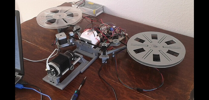
Concerning your question: there are quite a few options you might want to look into. Have a search for the keyword “tension” here in the forum - you will see that this is not an easy thing to achieve, and there are many ideas floating around. Using a potentiometer as tension measurement device is only one of the options. If you look at an old setup of mine,
you see that I am actually using tension arms with potentiometers.
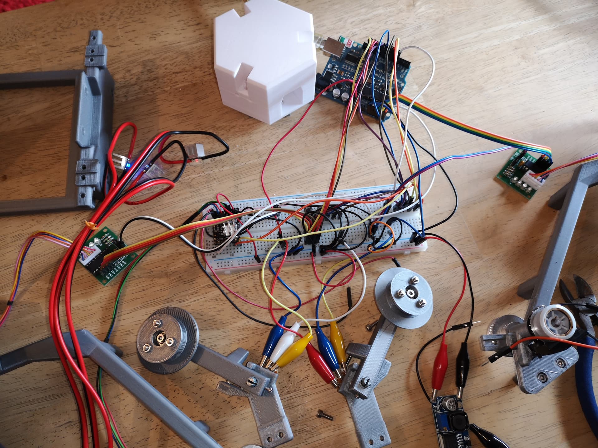
There are two tension arms visible in the photo above which measure the tension left and right to the film gate. Here’s an old image from a test setup where you can see more details of the construction:
Let me tell you right from the start: this is quite a challenging approach. For one thing, the angle resolution of the potentiometer + tension arm setup, if they are connected directly to a DAC, is very low. I did not bother to design a conditioning circuit with opamps and I paid the price later with developing a lot of weird software routines. You need to make sure that the voltage applied to the potentiometer is absolutely constant. Otherwise, you will get a sensor signal which is very in low amplitude and very noisy.
The basic principle is that the tension in the film path changes the angle of the arm on which a roller is mounted. This is because a small spring wants to push the arm in one end position and the tension from the film pushes against that spring in the opposite direction. So a certain film tension corrresponds to a certain angle of the arm, which is measured by the potentiometer. That is because the axis of the potentiometer is actually the turning center of the arm.
So, a certain angle corresponds to a certain tension which corresponds to a certain voltage reading from your potentiometer. So you have realized a tension sensor.
You can pair this sensor with a PID-controller to control the windup motors. The PID controller gets a set point and will move the windup motors in such a way that the measured value stays always close to the set point.
That’s about all with respect to the functionality of a potentiometer-based tension system. But do not underestimate the challenges lurking in the background. If you want to use only the small 15m Super-8 rolls, the PID parameters might be easy to determine experimentally. If you however want to handle larger rolls of Super-8 film (as in the image above), it will be a challenge to pick the right motors and PID-constants to make this work.
Some people substitute the potentiometers with micro-switches directly connected to the windup motors. That is actually an approach which is simple and works fine, provided you stay with low scanning speeds. Many other people do not create their own film path, but simply reuse an old Super-8 projector for scanning. While the mechanical stress on your precious film stock is much higher than it potentially will be with your own design, you will get much faster nice results when reusing the mechanics of an old projector.
Somewhere on this forum, there are servo motors described which supply a constant tension all by themselves. Depends on your budget whether this is an option for you.