April: Early Software and Köhler Lighting
As expected, I had almost no hobby time in the first half of April, but as my wife’s knee has been recovering, I found a little time to tinker over the past two weeks.
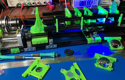
After a lot of time spent puttering with the 3D printed light path lens-holding setup I showed at the end of the March post, I still wasn’t getting anywhere. That initial design made adding/removing an element require sliding all the other pieces out of the track temporarily. So it wasn’t very friendly to the kind of experimentation I needed to nail down why I couldn’t hit both key Köhler points at once:
- Condenser position adjusted until field diaphragm is in focus.
- Field lens position adjusted until LEDs are imaged on the condenser diaphragm.
Despite moving the other elements around, I always seemed to end up with the two irises too close together or bumping into the endpoints of the aluminum extrusions I’d picked. The condenser diaphragm is supposed to adjust contrast, but when it’s close to the (in-focus) field diaphragm, it also starts to constrict the field of view.
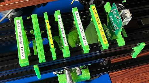
So I made another iteration: longer rails (using MakerBeam’s bigger, 15x15mm extrusion profile) and a “cartridge” template that can be removed in-situ with a half twist:
The first set also had a tendency to bind up on the four rails while sliding, so I took this opportunity to make each lens cartridge a little thicker, which keeps them better aligned and easier to slide. This meant there was enough thickness to get a little better organized with labels, too. ![]()
Being able to pop the elements in and out individually paid dividends almost immediately. In my first tinkering session after I had everything assembled, I had one of those nice, accidental discoveries: while swapping the field lens out to try a different one, I happened to glance up and see that the LEDs were better focused on the condenser aperture than I’d ever seen them. In ThorLab’s own setup, the light source incorporates one of those big aspheric lenses (the ACL5040U) and that was enough to act as a field lens without an extra lens element on top of that.
Now that everything was set up the way it was supposed to, I tried closing the condenser diaphragm. Controlling the contrast of your image by moving a little lever arm is cool!
Early Software
I’m using a GigE camera from LUCID Vision Labs (which I believe was founded by ex-Point Grey Research employees that left after the FLIR acquisition). So this earliest step was just to get their library (the ArenaSDK) turning over and on the screen. So I duct-taped ArenaSDK, OpenCV, SDL, and Dear ImGui together as minimally as possible to get camera images streaming in, stored in an OpenCV Mat, uploaded to the GPU as an OpenGL texture, and displayed (effortlessly with friendly UI widgets) using ImGui.
There isn’t much to say at this point because it doesn’t do much. The first test was just to get a “line scan” feature up and running like the one shown in the ThorLabs video. I was happy that it only took a dozen or so lines of code and all four libraries played very nicely together. (I haven’t done any COM port integration to talk with the Arduino to control the LEDs or stepper motor(s) yet. That’s for next time.)
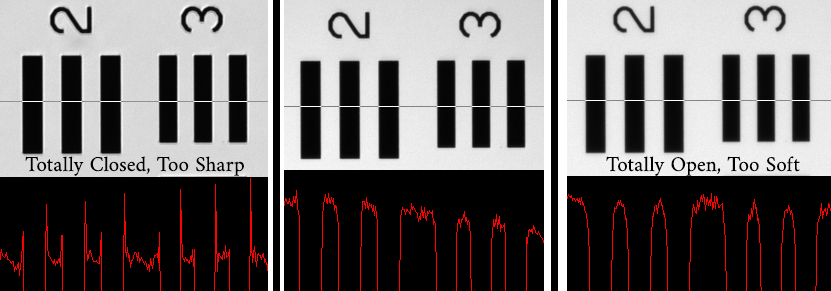
A few years ago I found an Edmund Optics 3"x3" glass slide USAF 1951 resolution target on eBay for 1/3 it’s usual price, and it has been useful for characterizing camera sensors ever since.
Here’s the (heavily cropped to keep it at native pixel size) kind of thing you get to see when you adjust the condenser diaphragm through it’s full range:
One limitation you can see even in this center crop is that there is more edge fall-off when things are adjusted properly. (The center line-scan appears to be tilted.) I’m not sure how much of that might still be fixed when I get a few more minutes to move these lenses around some more. If I knew more about non-imaging optics, I’d probably have a better idea where to look first, but I’ll resort to blindly guessing for now.
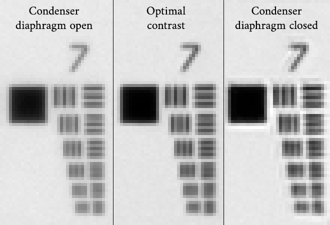
Down in the smaller group 7 elements you get an even better idea of what the contrast adjustment is doing:
Again, the only thing changing between these images is an iris being very slightly adjusted. The camera, sample, and focus position are being held constant.
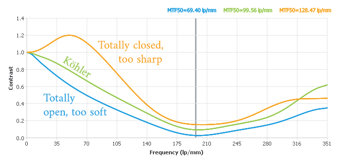
While looking around to see if someone had already done the hard work of being able to quantify these types of images, I stumbled on the delightful, free MTF Mapper app. You give it an image and it generates MTF response graphs from the rectangular-looking things it find in them. It’s got a lovely interface and was kind of a joy to use. There’s even a command-line version that I’m wondering whether I might be able to call right from my own (upcoming) auto-focus code to offload that work, since that author already did a better job than I’d be able to.
All you need to do is enter a pixel-size in the settings dialog to get the correct lp/mm units. I had a calibration slide on hand, so I could measure it more or less directly. (In doing so, I also discovered that my extension tube setup has all these images at 2.85µm per pixel, which is a little on the higher end of magnification–around 1.58x–than I’d expected (1.3x). It only barely fits a full R8 frame with only a small amount of perforation visible. I’m going to have to pull that out a little for Super8 frames.
That’s the chart for the previous series of images. This is still being focused by hand, poorly. All of this was captured at f/4.7 on the usual Schneider Componon-S 50mm.
My admittedly basic understanding of these charts is that the higher and farther out the line makes it (at the dip, before you start seeing the “reflections”) is better, but that you want a relatively linear response, too. So the green line is the best, even though the fairly wild, too-high contrast orange line is technically higher.
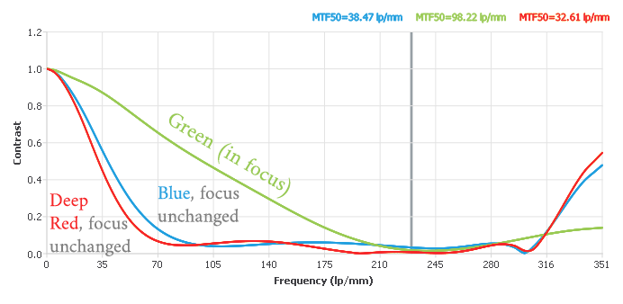
If you can hand MTF Mapper an image with a longer line to characterize, you can flatten out some of the Fourier artifacts past the dip. So I moved the calibration target to a lower-numbered group with squares that fill the entire field of view, switched to green light, refocused as best I could manually, and took a series of images with each color light: R, G, B, white, and IR. The results were really interesting!
(The early part of the green line (below 175 lp/mm) is essentially the same as before. I believe it extends farther and flatter because the MTF was calculated on a larger region.)
The interesting part is that taking the same image of the same calibration target without moving anything but only varying the color of the LED shows much worse results. (This is basically the definition of axial chromatic aberration.)
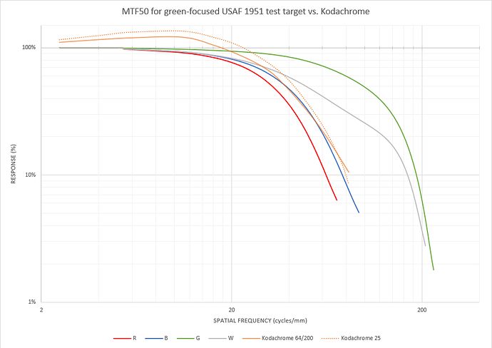
The units on both axes in these MTF charts are the same as the Kodachrome response curve (that I first saw in @PM490’s scanning resolution thread), except the Kodachrome datasheet shows them on a log-log scale.
I wanted to see the response I was getting with all the colors on the same graph as Kodachrome, so I went about trying to read the values from the datasheet graph. Reading data on log-log scales manually isn’t particularly accurate, so, again, trying to find a tool to help automate things, I bumped into the (also free, also delightful) WebPlotDigitizer which lets you upload an image, describe the axes, and even auto-trace lines. It supports linear and log axes in any combination, and it did an excellent job of giving high-precision numbers from Kodak’s log-log graphs.
I used an especially large screenshot from the vector graph in the Kodachrome datasheet PDF and carefully adjusted the points that didn’t auto-detect correctly. I repeated the procedure for both Kodachrome 25 and Kodachrome 64/200 (which, curiously in both the 2002 and 2009 year revisions of the datasheet have pixel-identical graphs for both ISO levels; I wonder if that was an accident that never went corrected).
In case this is useful to anyone else, here are the MTF data points I was able extract:
- Kodachrome 25 (CSV data)
- Kodachrome 64/200 (CSV data)
Each row is an X, Y pair with units of lp/mm and contrast response percent, respectively.
And now for the combined result with Kodachrome on the same graph as these test images:
White is looking pretty good, but focusing for an individual color does better! (IR wasn’t even worth plotting. It went to 0% almost immediately because it was so blurry.)
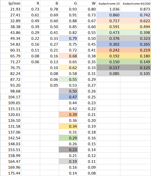
For the purposes of Nyquist and making sure this setup will be able to capture all of the signal available, when you look at the data table, there are some promising results:
The row highlighting corresponds roughly to where the green image is at double the frequency of the Kodachrome response, and everywhere above 40 lp/mm on Kodachrome, this system appears to be able to resolve as much contrast or more (often around 2x).
But the same isn’t true for white and especially not for the other individual colors, holding the camera focus constant. I’d been worried this whole time whether I was being a little… eccentric for wanting to investigate refocusing for each color channel, and at least after this early result, I feel a little vindicated. ![]()
It’s worth mentioning that there’s probably still a little more headroom on the table. These were all focused by hand, there isn’t any frame averaging so sensor noise is still a little higher, the light-path lenses are still loosey-goosey and not perfectly aligned, there is a ton of light spill from ambient room lights while my setup is still in prototyping mode, etc.
The obvious next question is whether the line for all three colors (or four if you count IR) can be pushed out as far as the green was when refocused individually. But, before I spend too many hours trying to turn this ball screw by hand to maybe-focus things and guessing whether I got close or not, I think it’s time for…
What’s Next
Auto-focus! It’s time to get the Arduino included with the rest of the early software and get that stepper motor turning in response to what the camera is seeing. If the problems @cpixip has described with the RPi HQ camera and its software library are any indication, I anticipate a bit of a learning curve with how long the different parts of the system are going to take to respond after changing the others. Will I need to wait after a color or focus change? How many frames? We’ll find out soon! ![]()
For a short month, this was a good one.

