The ReelSlow8 Film Scanner

I liked following the Sasquatch 70mm build thread so much, I thought it would be fun to also chronical my progress from (nearly) the beginning.

My name is Nicholas and I’ve been planning to build one of these things for almost a decade. I figured it was time to stop planning and start building, so my goal now is to complete some measurable chunk of work each month in 2023 (starting in Feb) to hopefully have a machine that does something by the end of the year (and write about it here as I go along).

The Starting Point

  • About fifty 3" reels of 8mm and S8 Kodachrome family movies shot between 1954 and 1985.
  • A Lucid Triton 2.8MP GigE camera: IMX429, 2/3", monochrome, 1936x1464, global shutter.
  • The usual Schneider Componon-S f2.8/50mm lens.

I like monochrome because it might give better control over colors and it could maybe squeeze more resolution/fewer artifacts out of an otherwise same-resolution sensor with a Bayer filter.

At 2/3", I’ll be running at 1.35x’ish magnification for 8mm film, which is a little higher than most of you RPi HQ folks. But, the extra 1um of resolution in CoinImaging’s “resolving power vs. magnification” chart (vs. 1.0x) that matches this sensor’s pixel size almost exactly made it feel worth it. The nice, deep wells on the Pregius gen3 sensors also felt like a good answer to keep the number of HDR/fusion exposures low. I’ll be curious to actually measure the dynamic range I can get out of this thing.

Areas of Interest

To answer “which features am I hoping will make the ReelSlow8 different?”, I’ve got a few experiments I’d like to try in the coming months:

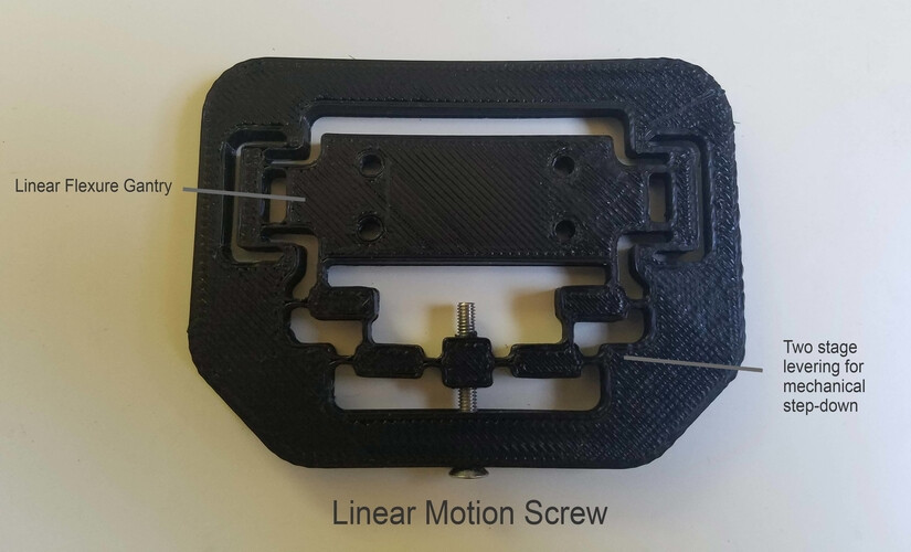
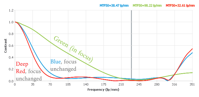
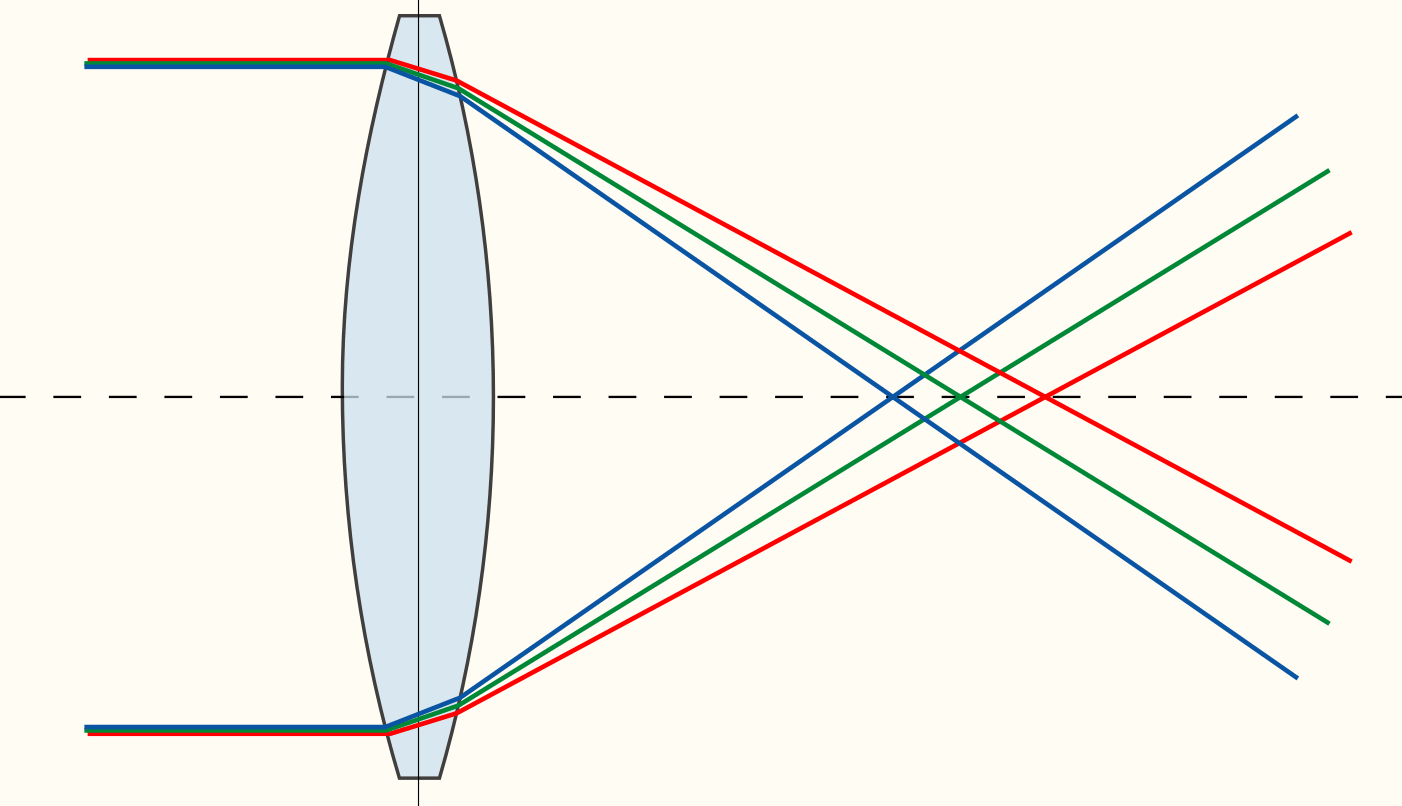
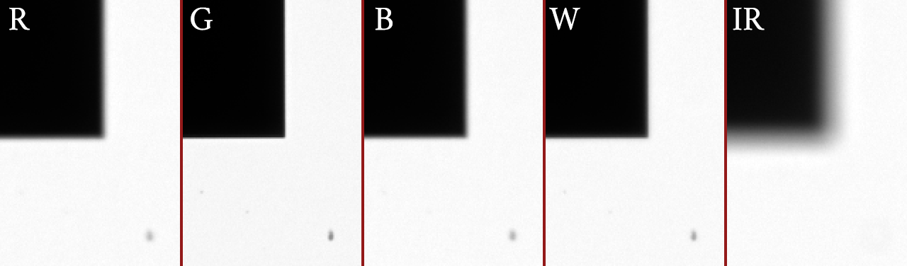
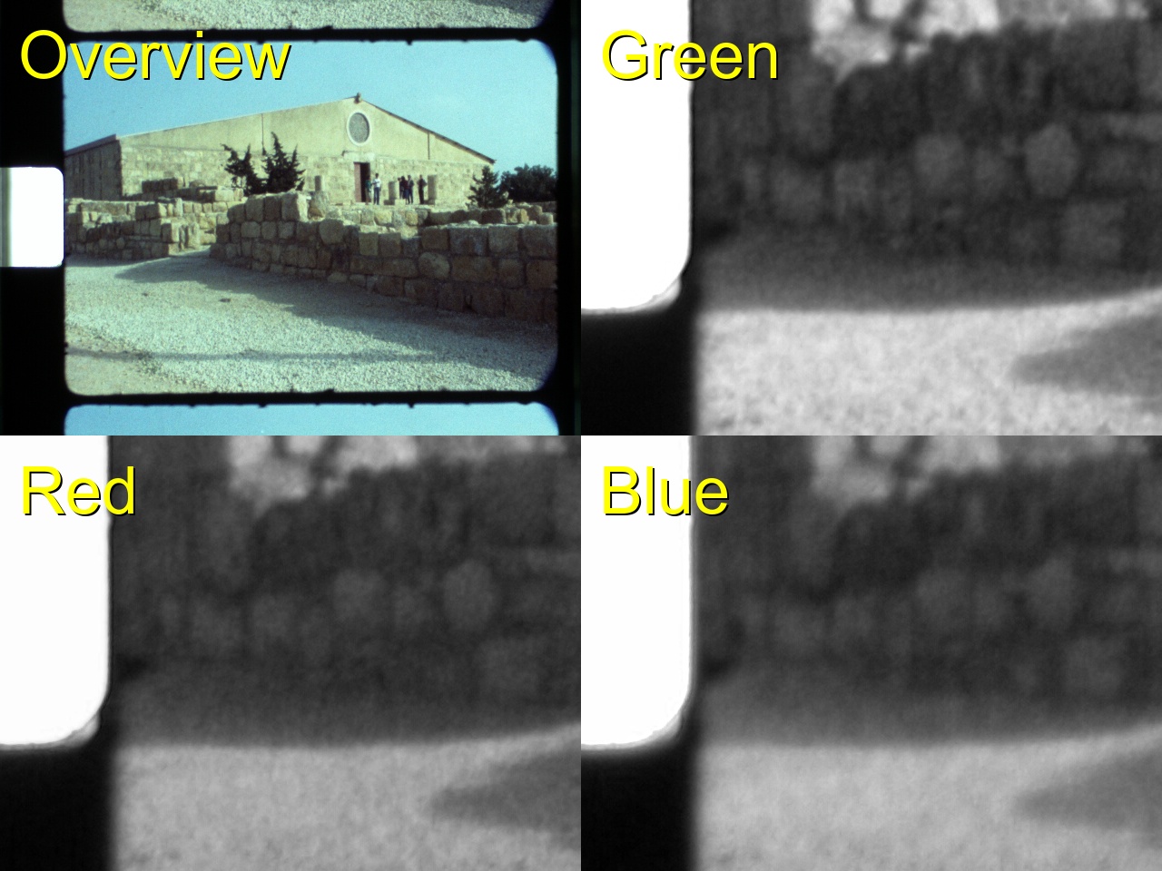
  • An overkill auto-focus system. I absolutely do not trust myself to dial in any part of this machine. I have this way-oversized (280mm) ball-screw linear stage that I’ll be mounting the camera on, controlled with a stepper. But even more than that, I want the image plane to be fully adjustable and under the control of software: one corner fixed and two others that are motorized so the software can get a more exactly parallel image plane than my hands on an adjustment micrometer. For the main camera focus axis, I want to be able to chase microns. I had a bad experience with a different lens that had lots of axial CA so I want this thing to be able to focus on each emulsion color layer individually, if need be.

  • A tiny 8mm wet gate. After poring over lists of strange chemicals (and their refractive indices) and having chemical supply companies turn me down for years, I finally found someone that would sell isobutylbenzene to a residential address! (The answer in the US is Chemsavers.com, but lab-grade reagents are ridiculously expensive. It’s frustrating when the one liter you can actually get someone to ship to your house costs more than the 50gal drum you’ll never be able to buy from Aliexpress… but that’s the world we live in, as far as I can tell.)

    For the curious: on all of Kodak’s literature about IBB, I’ve seen things like “persistent odor” mentioned a number of times, but never any description of the smell itself. I can now make a first-hand report: it’s a little like black licorice, but worse. :rofl:

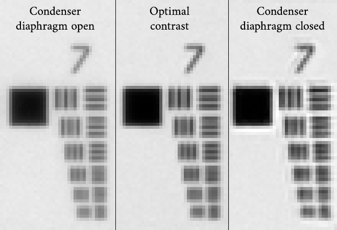
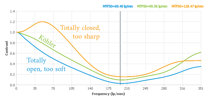
  • Collimated condenser/Köhler lighting (vs. integrating sphere/diffuse). If I’m going to the trouble of a wet gate with the right index of refraction, I’d like to keep as much of the contrast ratio intact as possible.

  • IR or dark-field cleaning. Kodachrome is partially opaque to IR, so I’d like to tinker with dark-field imaging to maybe grab a dirt/scratch channel. This is a lower priority because I have high hopes resting on good pre-scan cleaning hygiene and the wet gate doing most of the heavy lifting here.

  • Lots of post-processing. The VideoFred scripts are an inspiration to me. Temporal inpainting and motion interpolation are very exciting. And–more recently–adding “AI” onto the front of either of those terms yields search results that look a little like magic. My target is something as good or better than the “Thanksgiving dinner” video at the bottom of this page.

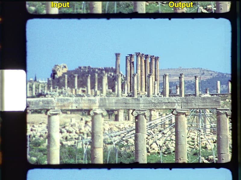
  • The distribution of these films to my family is just as important as the scanning. They’ve actually already been digitized once by a couple of my uncles, back in 2011. The best they had available at the time was a DV camcorder pointed into a projector + mirror box. The resulting 480i60 / 4:1:1 recording often had half the fields blown out by over-exposure when the scene brightness would change, frequent focus hunting, and the projector’s small, square gate hid about 30% of the image. :sweat_smile:

    But more than the possible improvement in image quality, trying to find the clip you wanted was the trickier part. The end result was a pair of DVDs with about 4 hours of footage in the order they pulled the reels from the old box. Unless you were planning to sit and watch all the way through, the only way to see the thing you wanted was lots of seeking and maybe a disc swap. For some of the “kids” (now in their 40’s and 50’s) that were featured, they might have to skim the whole collection to find the only 5 minute clip they were in.

    My plan is to make a simple, private website with a chronological timeline cataloguing each scene, a family tree at the top that can be clicked to filter for a particular person, and a list of categories (Christmas, vacations, weddings, etc.) to further filter the list. Ideally I’ll have enough metadata that someone could find the clip they’re looking for in only a few seconds and optionally save a copy to their phone/tablet in one more click.

    It’s a small detail, but if an old family film is scanned in the middle of a forest and no one is there to watch it, does it really exist? I try to keep in mind that the accessibility of these memories is just as important as their image quality.

February: Light Source

Let’s kick this thing off with some real work that I did over the last few weeks!

I’ve had some wacky ideas for light sources in the past. (See my profile pic for one bad idea.) I’d settled on a linear (non-PWM) multi-channel source and got some great tips a few years ago on a circuit design that only used a single LM317 to drive several different current levels.

I didn’t have variable current control high on my list of priorities but have since read here that these sensors can be much slower at changing their exposure settings. This sensor has a global shutter, so as a last resort I suppose I can use a timed pulse scheme if the camera ends up being uncooperative.

Because this isn’t a continuously running system, I don’t need to freeze the motion, so I can get away with a lot less light. That means having the convenience of low voltage and low current. This design tops out at about 2.5W (10V at 250mA), which fits neatly inside the spec for the 28AWG wires in a mini-DIN cable. So I was able to use a convenient single power+signal connector.

This uses a combination of Cree, Luminius, and Yuji LEDs. There’s a bit of kitchen-sink thrown in here with White, RGB, and IR channels. Because my project is predominantly exploratory/experimental, I didn’t know what I was going to need, so I included everything, hehe. The RGB wavelengths are 450, 525, and 660nm, which match the optimal wavelengths for decorrelating the color channels (as best as I could tell) from the chart in the Diastor paper. The IR channel uses 940nm. I’ve tried the (much more expensive!) 1050nm range in the past and didn’t find any difference with Kodachrome besides less sensor sensitivity; so sticking with the mid-900nm range was easiest.

The voltage drops on each LED were close enough that I was able to get two in series for each channel except red (with three), while running on anything over 10V. I’ve been trying to teach myself electronics over the last two years, so I also used this particular board to practice input and power safety design (hence the TVS, MOV, fuse, choke, and input protection which is almost all certainly overkill when it’s going to be run from a clean bench power supply).

Here’s the circuit:

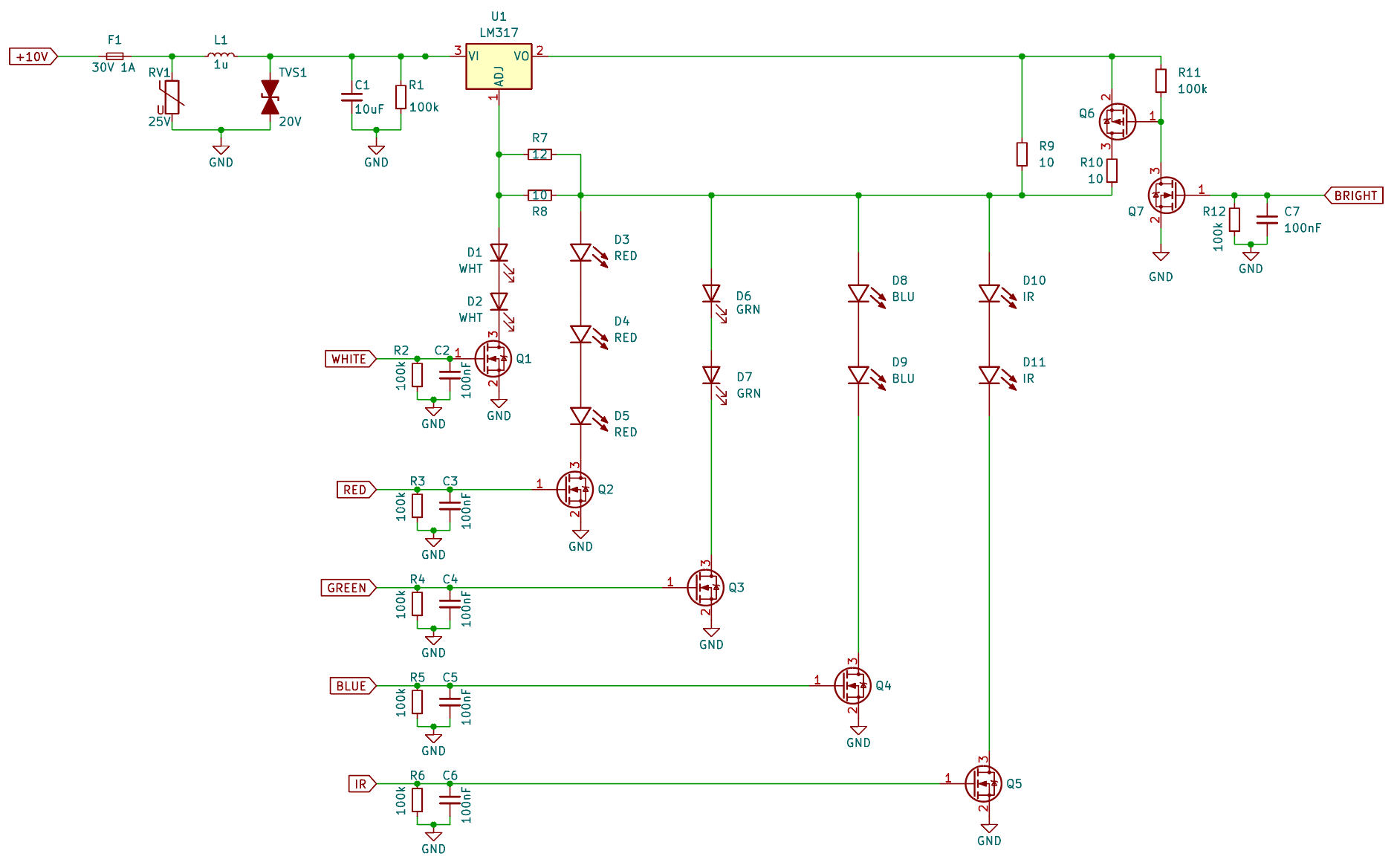
It uses the idea from that StackExchange link above where the LM317 will deliver a few different distinct current levels. The white Yuji LED needs a fairly precise 120mA to be inside its CRI spec. But the single-wavelength LEDs can go all the way up to 350mA. I decided to keep them around 250mA to be conservative. Then, because I had an extra pin left on my connector, I wondered if it might be handy to be able to toggle between two current level presets for the sake of controlling exposure times. It’s not quite like having a fine control knob, but it was only an extra high-side PMOS switch and now the individual channels can be toggled between 130mA and 250mA just by setting the “Bright” pin low/high.

The challenging part of the layout was getting all the LEDs to fit in a tiny square. My aspheric condenser lenses are 50mm, and I wanted the lights to fit well inside that circle. And even though they’re going to be well-diffused on the light input side, I still wanted the color channels to be radially symmetric around their center, which led to a lot of fun criss-crossy routing on my plain two-layer board. (This was exacerbated by my insisting that all the LEDs be oriented the same way for ease of hand-populating the board with tweezers. Changing their orientation would have made the routing easier, but I know I would have made a mistake and installed at least one backwards.)

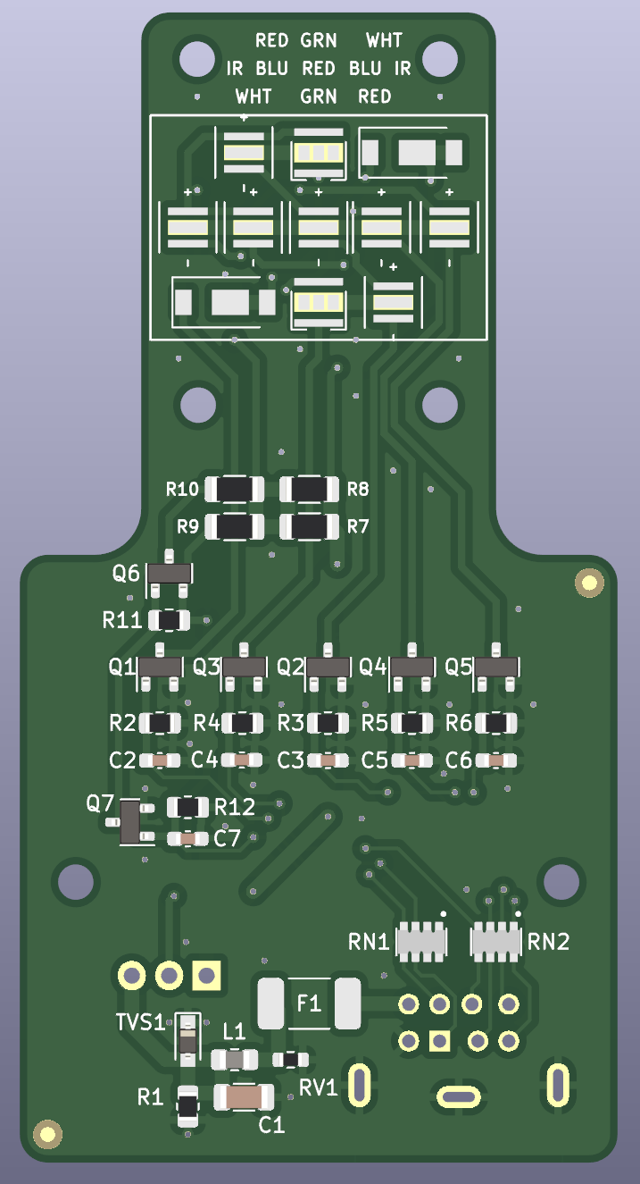
The M3 hole pattern at the top is only 16x23mm. Nice and tiny!

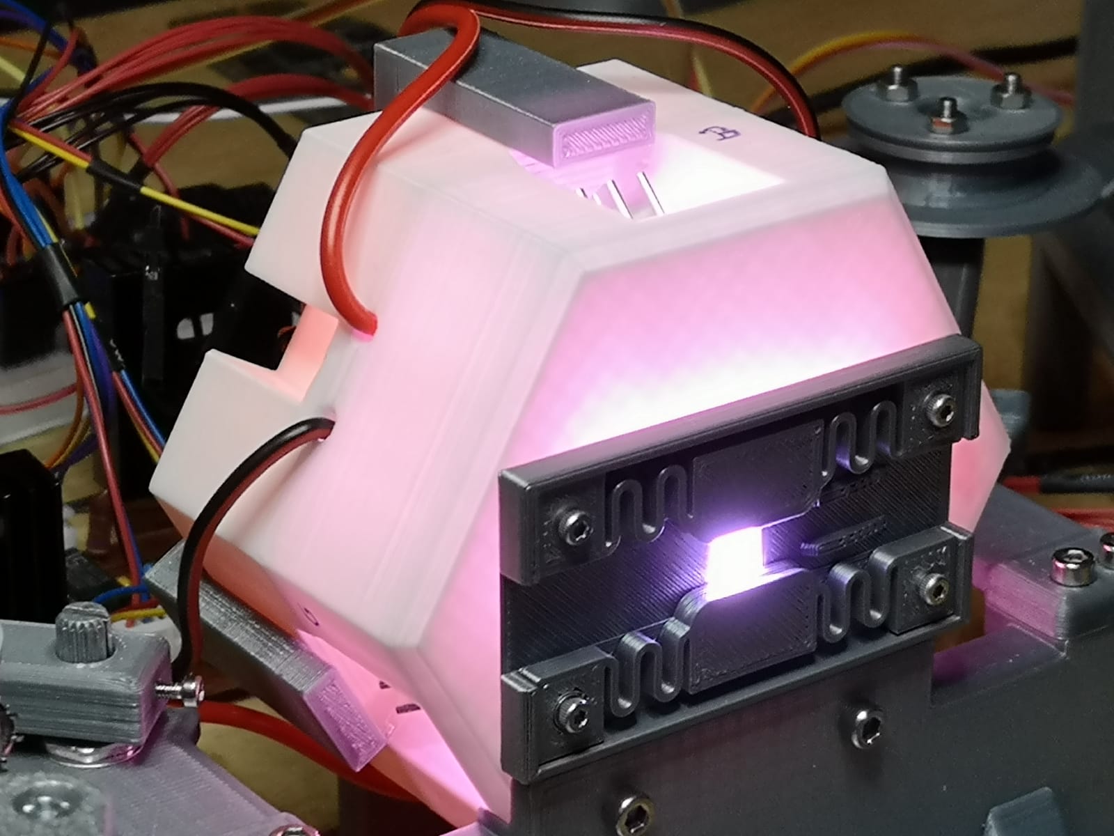
The inputs are tolerant of anything from around 2.5V up to 12V. I remembered I had a little Cherry MX key-switch tester and some solid-colored keycaps (from a different project) that coincidentally matched these colors. So I soldered a few wires directly to the key-switches to make a fun little test harness.

I have the light output turned way down for the sake of recording this demo video. Even just at 120mA and 250mA they’re painfully bright to be around normally. (The gray button I don’t press in the video is for IR. The one on the end is an old Cherry MX Lock switch that physically toggles on/off when you press it. That’s the “bright” signal.)

Eventually all of this will be connected to a microcontroller of some sort, but these clacky keys will work for testing in the meantime.

What’s Next

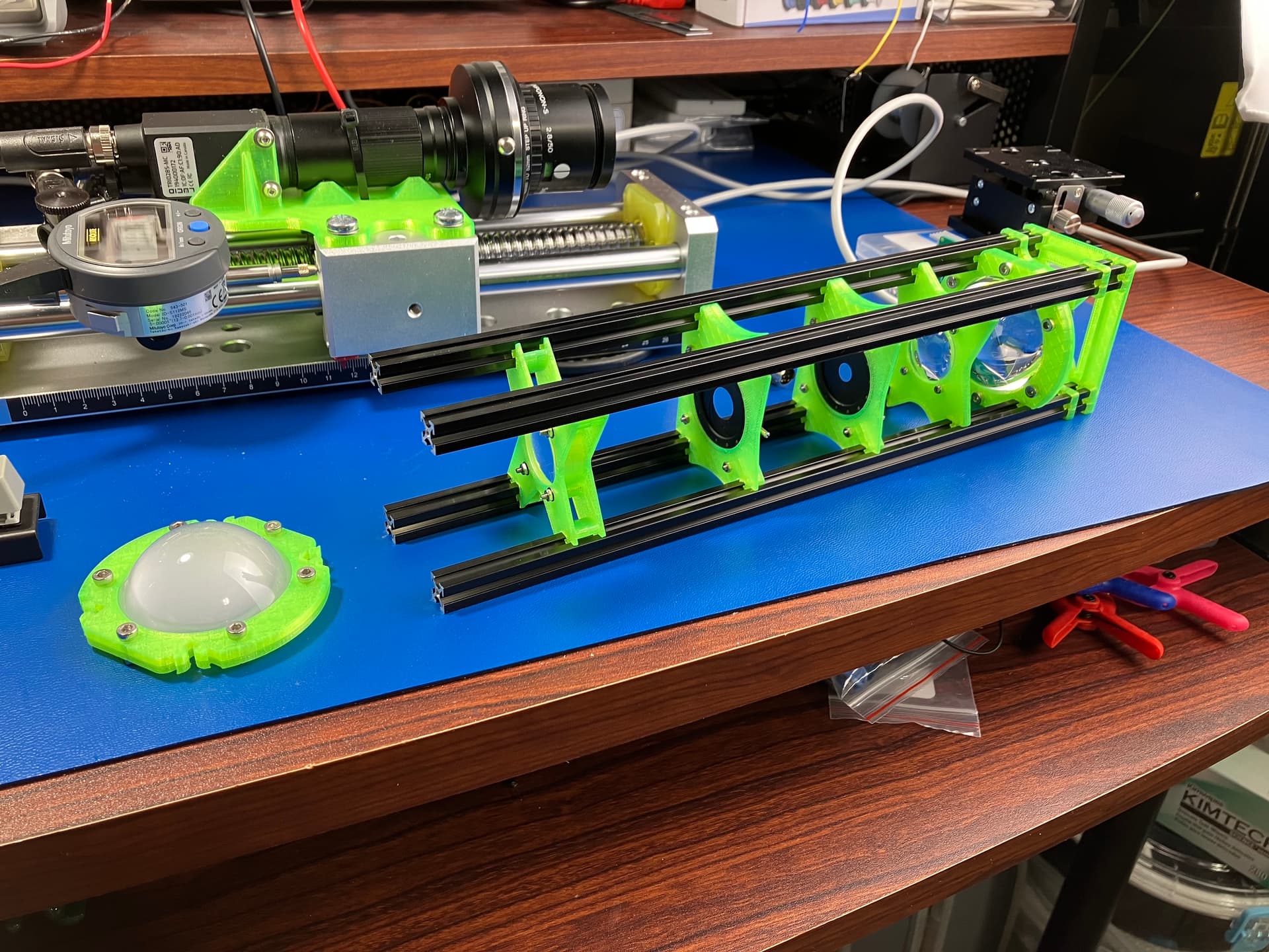
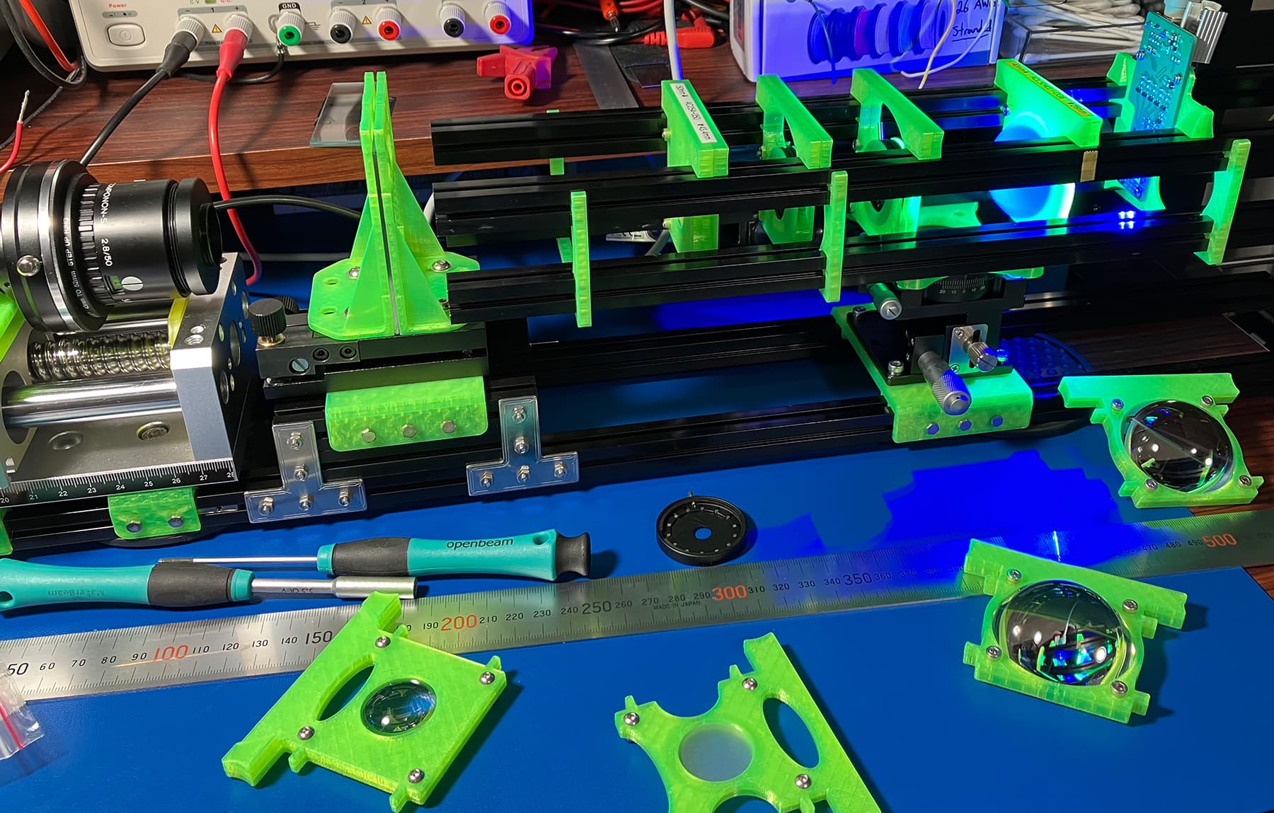
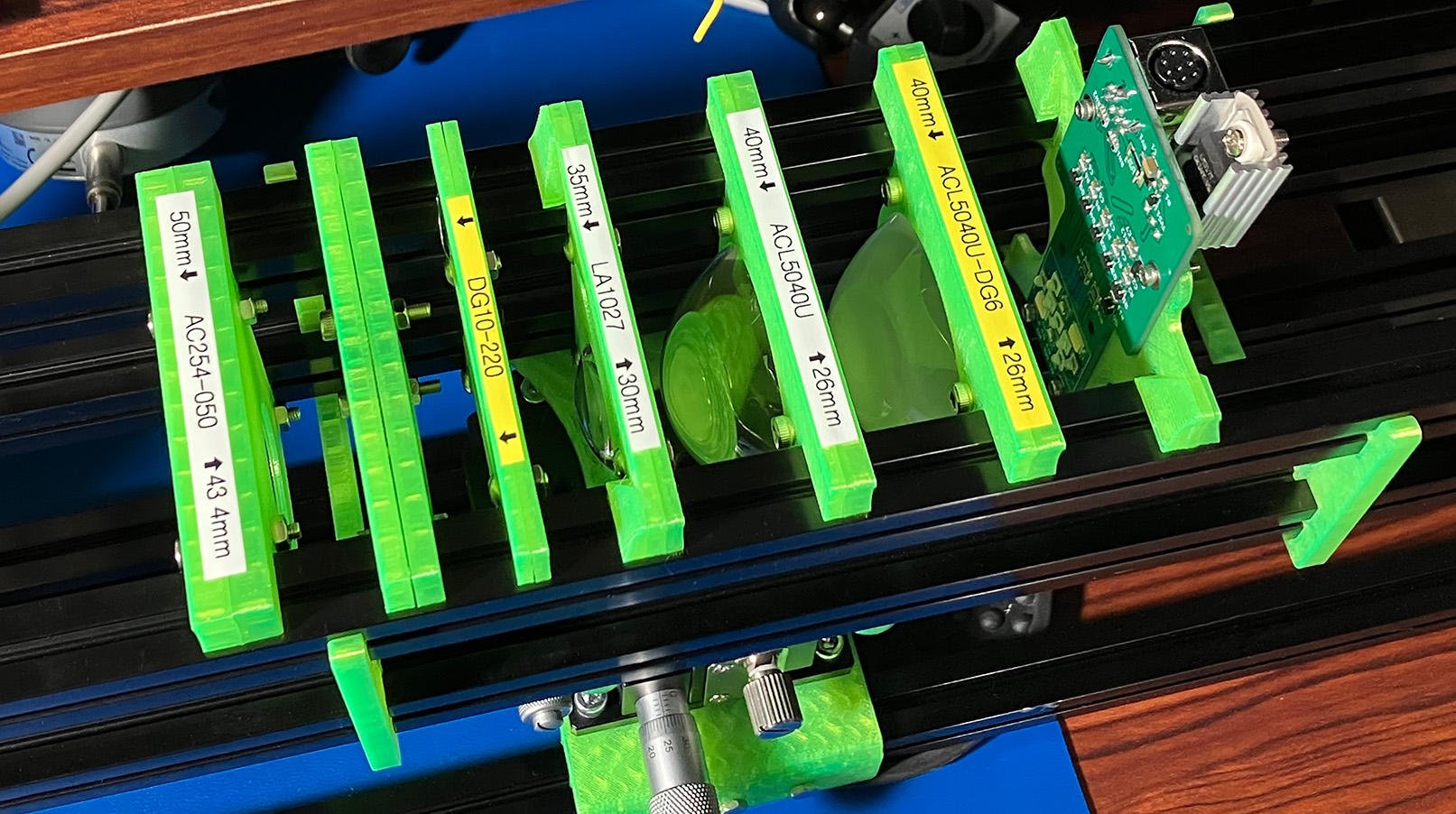
I’ve got a few immediate tasks before I can get started on anything more substantial. I’m planning to use MakerBeam’s 10x10mm and 15x15mm aluminum extrusions to hold everything together. Until it’s time to do wet-gate things, this is going to be a horizontal, tabletop build. So I need to get this mess connected to a rail system so I can start orienting things like imaging planes, the light PCB, and the condenser lenses:

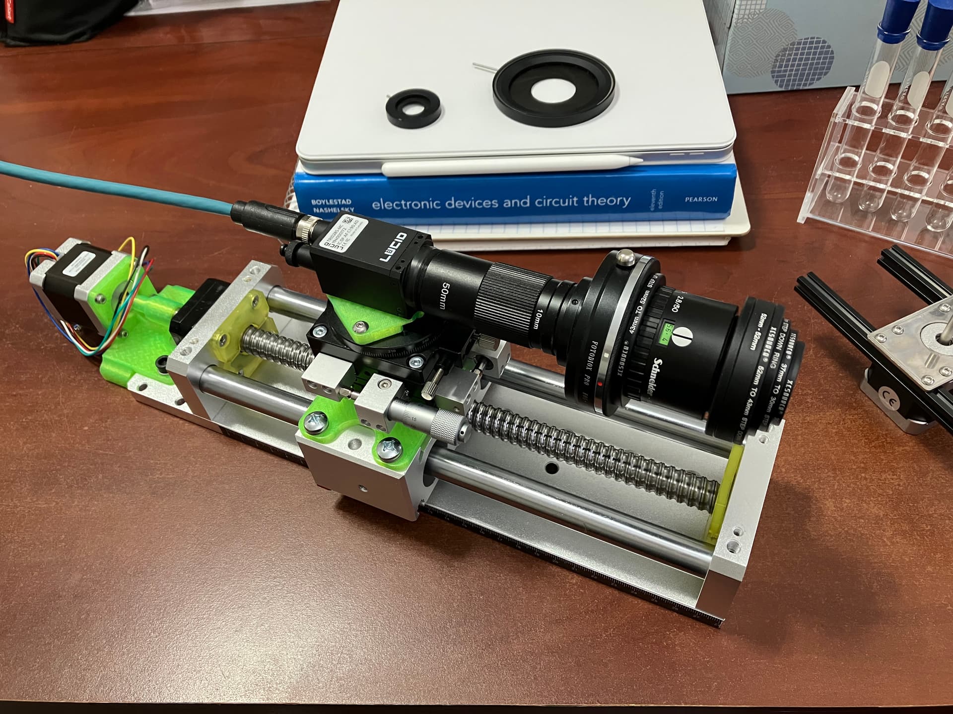
So far this is an example of how not to build a stable platform. Most of the 3D printed parts will eventually be replaced by milled/lathed aluminum. The stacked XY and rotation tables will be moving to the light source (so I can properly center things per Köhler illumination) and I’d like to get the sensor+lens a little lower and closer to its center of mass instead of flapping in the breeze the way it is now. (The only adapters I could find for reverse-mounting the lens involved a Canon EF-mount, which makes the whole chain pretty hideous and a lot heavier than it needs to be. The step-down converters on the front are just there to protect the exposed rear lens element for now.)

After that I need to dust off some microcontrollers and convince myself I remember how to drive a stepper motor. Hopefully I’ll be able to tackle all of that in March.

Whew. That was a lot of typing. :smile:

I am excited to finally start participating here and adding what little I’m able to discover to the great pile of accreted knowledge on this board. Please let me know if any of the above was confusing or if anyone has any questions!

6 Likes

Nice work and writeup, also really interested to hear how the sensor is going to perform. I have been going back and forth on which on to select. I wanted to have a resolution high enough to see the grain. The directed light + wetgate option for 8mm film is also something I’m interested in because of Diastor and the old Mueller HDS+ website. It claimed it’s not just more contrast but also a higher resolution I thought. The HDS+ ‘faux’ wetgate is already pretty effective according to the users in this thread ( and runs at 3fps):

The thread also includes several other interesting scaner user experiences btw.

Is the ball screw linear stage accurate enough for fine adjustments you want with autofocus on the individual emulsion layer?
I was thinking of using a compliant mechanism to focus on the film. I have build several of those for a different project and they are pretty great, here is an example of what I mean:


This is just an example of a linear stage btw, the topology can be used, but the dimensions would have to be altered for your usecase.

2 Likes

Thanks. And I know what you mean. I’ve been going back and forth in my head for years. Whatever the outcome, I’m happy I’ve finally given myself a deadline so the “analysis paralysis” can come to an end! :sweat_smile:

I suppose I could see that being the case. The CoinImaging reviews show that the two are almost the same phenomenon, in the same units, plotted on the same chart. You stop counting resolution when you can barely make out the line pairs on a test target. Contrast is when the brightness difference between the lines and background are still above a certain threshold, right? So increasing the contrast should give you more resolution for free (until you’re down to single-pixel line widths in the case of using a digital sensor).

The first time I saw the FilmFabriek’s little sponges years ago, I remember thinking it seemed like a very clever solution. I still have full-immersion in mind, but am ready to double-back to the good old “soaked washcloth / surface tension” method if things get too messy.

And quite a bit of contention. That was an… interesting read. :grimacing:

Although, even that sort of discussion is still useful to a beginner like me. I have about three hours of experience with 8mm film projection and zero hours of film scanning. So hearing about a few of the more common problems that are likely to come up from people with decades of experience using lots of different machines is valuable. Thanks for the link.

This is something I was hoping to measure and characterize (and share my results here). I have a dial indicator (with a data cable) that is spec’d down to a repeatability of 3µm. Once I get the motor wired up and under control, I was going to mount the indicator and run a bunch of automated tests to see what the movement actually looks like.

If the layers shown in this Kodachrome cross-section (third image in the carousel) are to scale and we estimate using an overall film thickness of 0.145mm, each color layer should be around 7µm. This article gives another data point that agrees. Beyond that, the len’s own chromatic aberration will shift things around from there.

The results of those tests will also inform my decision on what level of microstepping makes sense (or whether I need to drive it through a reduction worm gear, etc.). This particular linear stage moves 5mm per shaft revolution. The stepper is the finer 0.9° per step type (vs. the more typical 1.8° step size), so on paper that should be 12.5 microns per whole step. So by 1/16th microstepping, it should already be sub-micron.

… I’m sure the mechanical reality of these parts is going to make things more interesting than that, though. At a minimum, I should at least have some cool graphs of jittery lines to show off here. :smile:

Even if it goes perfectly, we’ll see if any of that makes a difference at f/4.7. I know that an IR exposure (should I choose to include one) is almost certainly going to require per-frame refocusing due to CA, so the goal is just something reliable and repeatable that I don’t have to do by hand. In that case, overshooting the requirements seems like a better plan than undershooting them, hehe.

I’ve never had a chance to use them, but flexure stages are so cool! I was amazed by this demonstration (the minute or so starting at 6:10) on how CD players use EM-controlled flexures to track the pits in a CD in real-time while the disc is spinning.

The couple of times I’ve thought about something like super-resolution (what they called “microscanning” on page 4 of the thread you linked), it seemed like a compliant stage and a couple of copper coils should be enough (with lots of hand-waving) to turn any monochrome sensor into a pixel-shift sensor. I already have enough experiments queued up though, so I don’t expect to go down that path during this effort.

Using one with a screw for fine focus is an interesting idea. If the stage were made out of metal–like this one using at-home EDM(!)–I would trust it more. With a 3D printed version, I’d be worried about material fatigue. My three year old son once asked me to print this little single-piece catapult. He left it in the “loaded” position overnight and the next day it would barely return even 1/3 of the way to it’s original position.

But, if the coarse focusing was very good to begin with and the screw was only used ±1 turn or so from its neutral position, it’d probably be fine for longer term use. My background is not in anything mechanical, so I don’t know exactly what that property is called. After a bunch of searching just now, I think it might be creep? So, if it has to be printed, maybe a lower-creep material like PC or nylon would be better for the task than something like PLA, at least, according to Reddit.

Either way, I love seeing all these ideas! All of the commercial scanners have to be optimized for throughput, which means they tend toward using a lot of the same design language. Once you get into the smaller, low-volume, niche builds where the speed doesn’t matter as much, there is a lot of room for creativity.

That thread imho is a gold mine of inside info, it’s sources like that this that show me that building scanners is a lot more about saving ‘information from decay’ than anything else.

If the ball-screw stage is repeatably accurate than that’s very good, but they are also too expensive for myself.

Yes BAXEDM has made a very cool machine indeed, if I ever were to create an EDM machine this man is who I’d hit up. But if I was convinced of my design I’d sooner just order it to be made somewhere.

Pixel shifting is certainly cool, but I’d rather just use a higher resolution sensor when more pixels are needed.

Your right about the creeping issues with polymers, it’s especially bad with PLA! I personally only use it for unloaded stuff. I had more succes with PETG and a especially using a slightly more difficult material PP. I haven’t used Nylon and ASA, since my printer can’t actively remove moisture from the spool and filter the fumes (it’s on the to do list). But there are still plenty of other avenues to explore regarding additive manufacturing.

You can also creating using leaf springs and cnc milled blocks, and bolting everything together instead of EDM. But my quest to create 3d printed polymer compliant mechanism is naturally driven by cost and availability.

March: Z-Axis Testing

To build an overkill auto-focus system, I need to be able to split hairs. So I spent most of my month staring at stuff like this:

Stuff that was tested

The stuff doing the testing

  • Mitutoyo 543-501 indicator
  • Mitutoyo 905338 cable
  • A NogaFlex magnetic holder and base
  • An Arduino

As an aside, that Mitutoyo indicator is way better than its spec sheet indicates. It lists a repeatability of 3 microns, but I saw hundreds of consecutive readings at the exact same number (despite a motion of >5mm between each reading). It’s also a joy to read from electronically. Their hardware interface requires zero additional components; each pin can be wired directly to an Arduino digital I/O pin. It’s designed to only need ground “signals” and can work at any system voltage (from 1.6V to 14V, anyway) so it can be dropped in just about anywhere.

Key Take-Aways

  • The ball screw exceeded my expectations.
  • Backlash was around 4.0µm average and 4.9µm in the worst-case, at all microsteppings. I was expecting an order of magnitude higher. (A human hair is 70um thick!)
  • Sub-micron positioning is possible without exotic workarounds like planetary or worm gears. It can even be done at convenient/fast microstepping like 1/32nd or 1/64th instead of out at the edges around 1/256th.
  • The frame, rigidity, and rotational smoothness were all nicer than I was expecting for the $180 price point. There are a few other listings on Amazon for similar axes around $100 but those reviews say that a lot of corners start getting cut and the quality suffers.
  • Doing all of your stepper driver configuration over SPI is convenient. The TI chip on the Pololu board can be chained together to control multiple motors using few I/Os, faults can be queried for more info, and it’s generally a nice, rich platform.

I actually spent a good portion of the month chasing weird patterns, strange behaviors, and other things that didn’t make much sense. I’d been using 12V up until that point because that’s what the LED board uses and I was hoping to get away with only needing a single power supply. But once I bumped up the “bulk capacitance” at the V_motor pins and cranked my benchtop supply to its max of 32V (immediately releasing the magic smoke on the LED board that I forgot was still plugged in :grimacing: ), all of the “weird” behavior disappeared immediately.

Coincidentally: all of the circuit protection stuff I mentioned in the February update came in handy. Only a single TVS diode burned out and the rest of the LED board was fine. The real lesson here is that the PTZ fuse should be rated lower than the TVS diode’s forward voltage. :sweat_smile:

After increasing the voltage, the testing became almost dull in its consistency. This motor can do short forward/backward motions all day long and it’ll read the same number on the indicator with one caveat: after hundreds of cycles there will eventually be a micron or two extension on the far end of the walk.

Whether this is actually the Mitutoyo indicator finally showing a weakness, I don’t know. (Every measurement inside that graph is technically inside its own 3µm repeatability error tolerance.) My working hypothesis is that the ball bearings are actually cutting a sort of “groove” in the lubricant after so many cycles. For my purposes, this is already well beyond the resolution I was hoping for and it shouldn’t matter. Worst-case, instead of doing a single auto-focus pass at the beginning of each reel, maybe it’ll make more sense to refocus every 50 frames or so.

There was only a single behavior I wasn’t able to track down: some combination of speed, length of walk, acceleration, (or some other factor that I’m missing) would cause it to lose position by about a micron or two every cycle. If you cut some or all of those variables down “enough”, the problem goes away and the position readings switch back to being as rock solid as the graph above. As much as I’d love to finish tracking this down, it’s kind of irrelevant for my purposes (I only need short, slow movements where it doesn’t show up) so I’m going to press forward instead.

Köhler lighting

I lost about a week in March to a stomach bug, so I didn’t get as much done on the Köhler lighting side of things as I wanted. I 3D printed lots of little adapters for these lenses and irises to make a kind of testing harness, but I haven’t really had a chance to quantify anything yet.

I mostly only learned that I don’t really have a working mental model for non-imaging optics. :sweat_smile: Anytime I thought I could predict what was going to happen, I was exactly wrong. So I’ve decided to try and reproduce the ThorLabs setup as closely as possible (from the 2nd video in the list there).

(Buying the lenses used there individually costs about $170 instead of the $11k(!) for the whole kit. I’ll take the 3D printed fixtures any day!)

What’s Next

Hopefully next time I’ll have more to say about smooth, even, “perfectly out of focus” direct light. My wife just had knee surgery a few days ago so I’m currently in charge of her along with our 3 and 7 year olds for the next five weeks, so I’m guessing April is going to be pretty light on hobby time. After that it’ll be full speed ahead again, though.

2 Likes