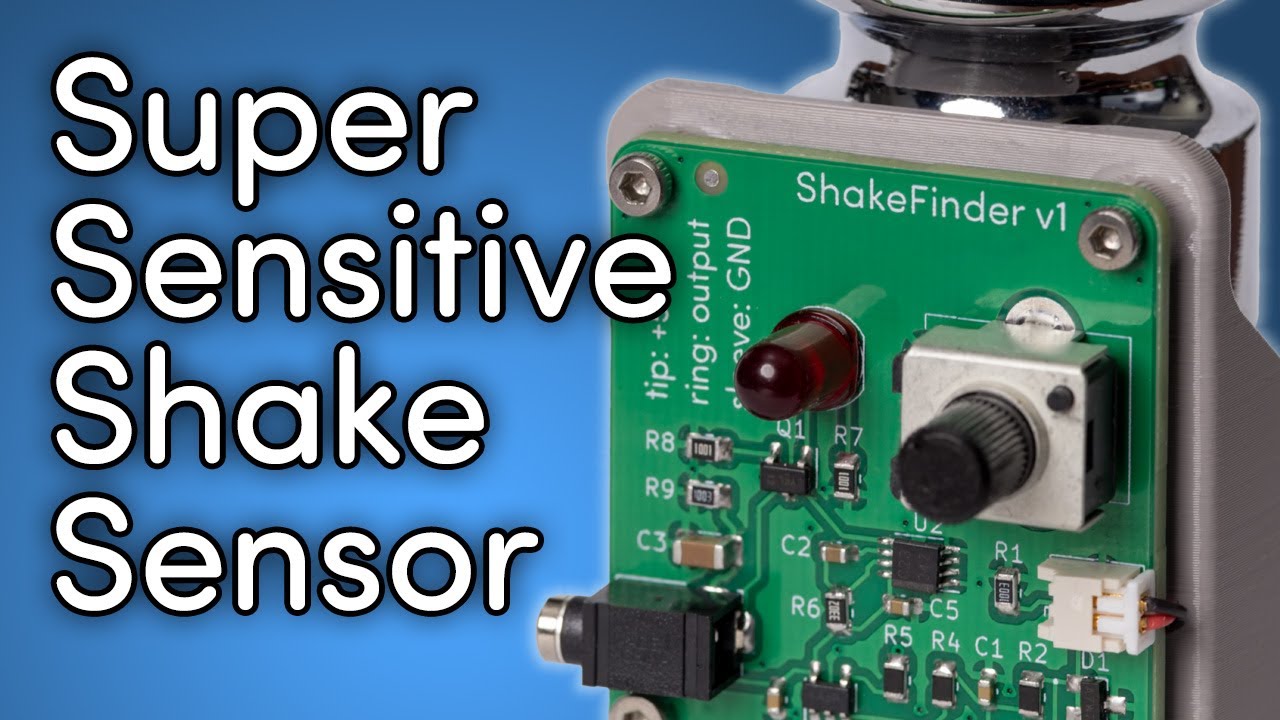
Interesting question, as it touches on an old topic: analog vs. digital. The unit @npiegdon designed is doing most of the processing in the analog domain. A typical MEMS sensor does this mostly in the digital domain.
Let’s compare @npiegdon’s approach to a MEMS-based approach of an old MEMS acceleration sensor I have in my part bin, the Bosch BMA180.
First, by design, the piezo-based sensor is measuring only deviations of the standard g-force near the scanner. Technically, you see something like a derivative of the z-component of g(t). The BMA180, as any other sensor of its kind, is however supposed to measure the real vector components of g = (g_x,g_y,g_z). On earth, and given a proper orientation of the sensor, you can rather be sure that two of these three components are close to zero and the third one will be close to 1g. This creates a dilemma for your shake sensor design: in my example, the BMA180 features a 14bit ADC. You need to set the working range of the MEMS to at least 1g (to cover the earth environment) - so the resolution for tiny movements in the z-axis is limited. Indeed, the BMA180 features a 14bit ADC, which gives you a resolution of 0.25 mg in its 2g-mode.
Note that this MEMS-signal is g(t), not the temporal derivative (that is: the shaking signal) we are interested in. The MEMS-signal will most certainly be quite noisy, due to the quantization level of the MEMS’ ADC - so good luck to compute a reliable derivative signal out of the incoming data. Also, the further signal conditioning @npiegdon nicely describes in his video (handled basically by a few passive analog components) needs to be handled by the processor driving/reading the MEMS-sensor at a fast pace (Arduino/RP2040/Raspberry Pi might be the usual suspects). Implementing this processing consumes resources on the processing unit and yourself (during implementation) - you might end up in allocating an exclusive processor just for the signal conditioning purpose, with quite a handful of parameters to be tuned in the process. Not something I would go into…
Of course, you could make your life easier and simply switching the MEMS-sensor into it’s “Tap sensing” or “Slope detection” mode (if available). Indeed, the BMA180 would in fact do all the processing for you and just trigger an interrupt if it detected the specified event. But: you’d loose the easy adjustment to your environment (table, house, kids) @npiegdon’s analog approach features. Furthermore, you do not really have much insight into the specifics of the algorithm the MEMS-manufacturer implemented - besides the information he is willing to share with you in the datasheet.
So summarizing the above thoughts: a MEMS-sensor would initially not measure the signal we are after and thus require more compuational resources on the processor side. The digital signal conditioning needed to arrive at a usable “shaking” signal demands an elaborate processing pipeline. Even then, due to the limited signal resolution available with a MEMS-sensor, we might not get the sensitivity we’re after in this application. The latter challenge will also exist if the computing capabilities of the MEMS sensor are used, instead of an external processor unit. In summary: I think for the application we are discussing here, the old-fashioned analog way wins in many respects.
![]()
