[v2 dev] Milestone 1 - PCB Design

Summary
Translation of current wiring into manufacturable PCB board.

Currently the wiring for all of Kinograph’s electronics was done manually. This is very time consuming and error-prone for anyone else building a Kinograph. The goal of this phase is to make a printed circuit board (PCB) so that the wiring is very simple for anyone setting up a new machine.

Required

Deliverables

  • PCB board files
  • Blog post sharing the files with community
2 Likes

Hi all. Happy to say this is underway now. I’ve asked the contractor to follow the pinout and form factor of the Arduino Mega. There will be plenty of pins left over for people to use as they wish. We will also include a bunch of screw terminals for those pins for easy hacking.

I asked the contractor about using KiCad so we could remain in the open-source world, but he said he was more comfortable with Eagle, so we will be using that for this phase.

Here is a link to the documents I sent him that describe the system as it currently is: Dropbox - kinograph - Simplify your life

I should have some updates from the contractor to share by next week.

2 Likes

Sounds great Matthew!

Reading through everything. Hoping to dive in soon-ish

Hi all,

The plan for the circuit design has so far been to create a single design that can be ordered from a PCB manufacturer on-demand. It will include lots of open pins using the Arduino Mega form factor so there are ample opportunities to add features/functionality or bypass existing logic however you please.

I am wondering, however, if there is a desire to also create athrough-hole version of the design so people could mill/etch their own. So…I’ve created a poll to test for demand. Of course, we can always go back and do this later but I thought I’d check-in now since it will be easiest to do it all at once with the contractor we have.

Is having a through-hole PCB design important to you?

  • Yes
  • No
  • No opinion
0 voters

Getting PCBs made is so cheap (and high quality) that I believe it there are smarter ways to spend your time than on making an alternative PCB design.

I’m joining this thread a bit late so if the horse is already well out of the barn then …

Assumptions

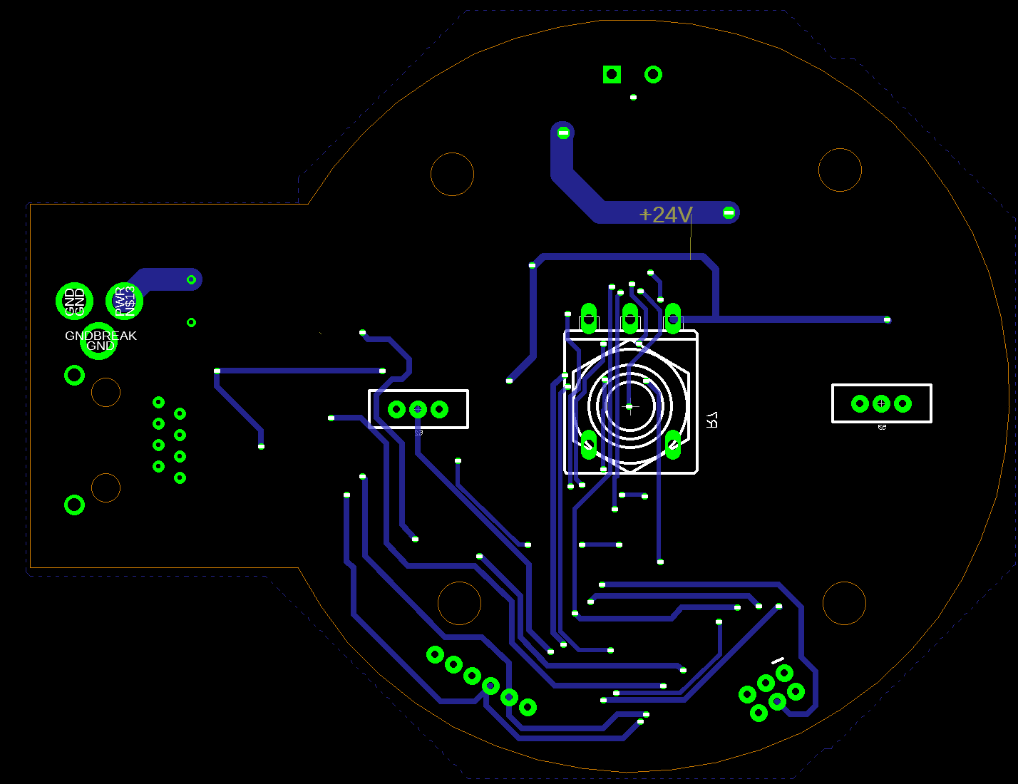
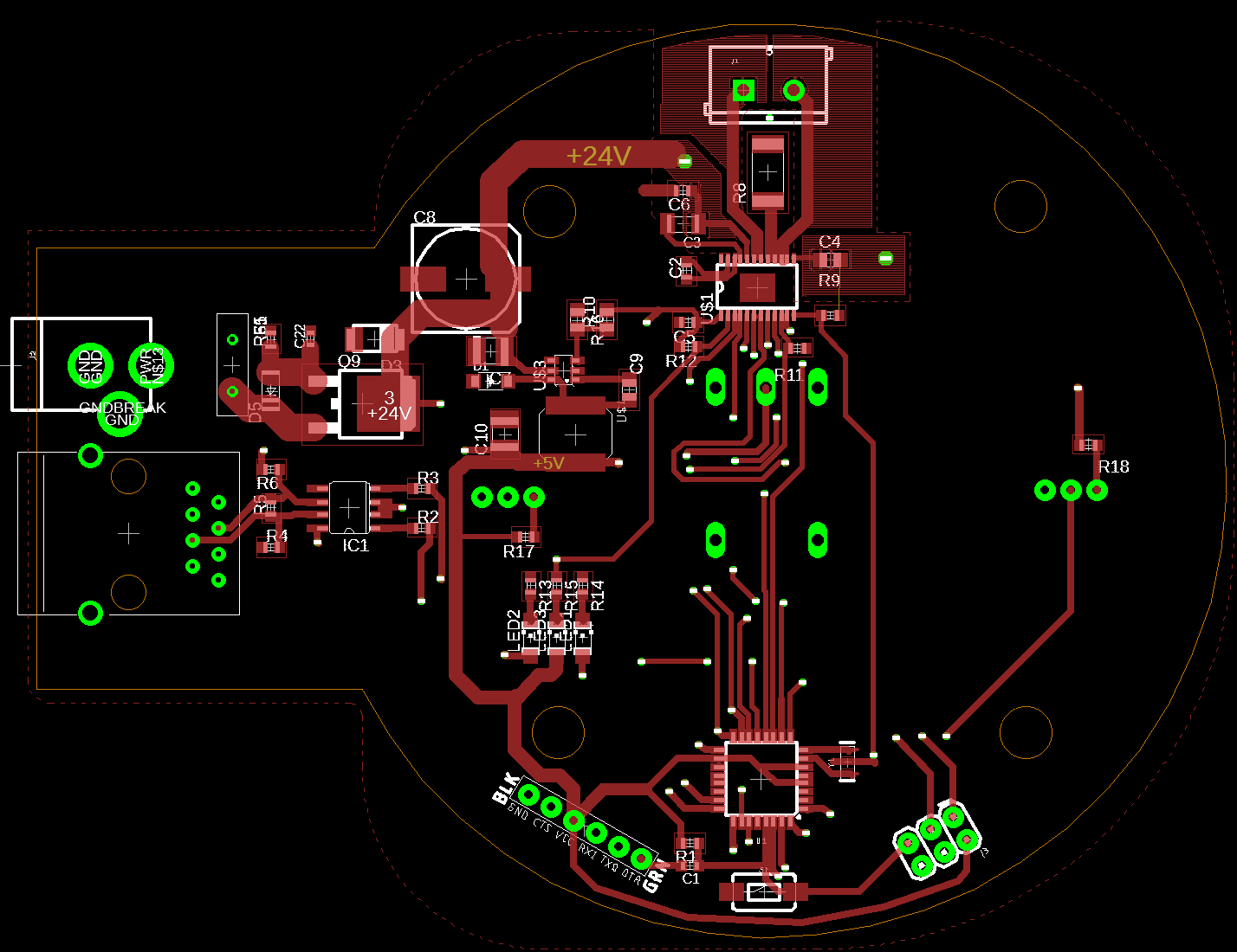
  1. Currently, the controller will be a custom designed circuit built on a custom designed printed circuit board.
  2. The PCB, at least first pass, will use surface mount devices.
  3. The PCB will be more than two layers (probably).
  4. The PCB schematic and board layout will be open sourced.
  5. The overall system/product will most likely be end-user assembled in the first phase of product build.
  6. This is a very low volume, moderate complexity product. There is a lot of electrical / electronic / mechanical interaction.
  7. Going forward there may be a manufacturer selling fully assembled units, most likely though all units will be assembled by end-users and/or low-volume manufacturers.

IMHO
I don’t see the rationale for using a custom designed circuit; building the controller from widely available modules and parts would seem a better path.
Custom designed circuitry/PCB are usually motivated by a mix of:

  1. High volume
  2. Need for very low cost or good profit margins.
  3. Unique or complex functionality better implemented in custom hardware.
  4. Requirement to use sophisticated components that seldom seen in mainstream commodity hardware.
  5. Personal motivation (Hey! I like to do custom electronics and PCBs)
  6. Unique requirements to comply with regulations, e.g. RF noise generation or sensitivity.
  7. There are size and weight constraints.
  8. There are power (to operate) constraints, e.g. has to run on a coin-cell battery for 6 months.
  9. Assembly from modules would be too onerous for the typical “builder”.

I don’t think this is a high volume “product”. Cost needs to be reasonable however the bulk of the cost for this product is in the rest of the machine. The size, weight, and power constraints are very minimal. As a system overall this is a complex product; the controller is not. So far there are no exotic functions or components needed in the controller.

Consider additional parameters for the controller:

  1. Design for manufacture
  2. Design for repair
  3. Extensibility

DFM
The machine overall hence the controller will most likely be manufactured (assembled) by an end-user or “maker”, not by a commercial entity. The sophistication of available tooling is limited. If the controller is a single custom circuit board with cable/wiring connectors it is the typical “black box”. This approach would shift the DFM issues from physical assembly to sourcing, i.e. where can this custom board be acquired fully assembled?
Yes, the design/build information will be open-sourced. Will the controller builder be experienced enough to get the controlled build and assembly accomplished. A 4-layer PCB with SMT components will have to, in virtually all cases, be commercially built. Clearly doable, but perhaps beyond the range of typical end-user experience/skill. Yes, a large number of makers get involved in PCB design-build, but no where near a majority.

DFR
For me this is paramount. Use of the machine will probably be front loaded; lots of activity in its first 6-12 months and then sporadic use over the next 6-12 years.
What does an end-user do in 6 years when the parties involved in launch are long gone? A failed motor driver circuit or “flaky” controller board will most likely require controller replacement; controller repair will be beyond then available resources. Who is going to build this controller board?
Details of future failure modes of the controller are hard to predict, one certainty is that with a custom board (4-layer, SMT) the repair for all failure modes will be replacement of the entire controller. Sourcing may not be an issue today, but where will it be in 6 years?
This would seem to motivate controller assembly from a set of widely available, commodity level modules. Is someone going to be making an Arduino Mega or Sparkfun Redboard in 6 years? I think so.

Extensibility
Certainly replacing the entire controller is one form of extensibility., but perhaps not the type of extensibility that supports experimentation.
What if the current design of film tensioning with mechanical limit switches and dancer arms is replaced by a vacuum chamber system? That would be much easier on the film physically, but could the controller support the new types and number of sensors required? Just one example.

Conclusion (finally)
It would seem that using a modular hardware approach would offer a lot of benefits for a device that at launch will be in the minimum viable product (prototype?) stage. An implementation example could be an Arduino MKR1000 with Arduino MKR Motor Shields, or a Raspberry Pi with a variety of real-world sensor and motor control hats.

Well that my $1.00 (way more that $0.02).

Ric
1 Like

@Ric, thank you for a phenomenal post. You make a lot of really strong points. All of your assumptions are correct, but you are missing one part which I have failed to make clear. The PCB that is being designed is a shield for an Arduino Mega, not a standalone PCB.

I completely agree the electronics should be as modular as possible. The shield will serve a couple of purposes:

  • quick connections to components and/or daughter boards
  • screw terminal access to unused pins
  • easy swap-out capability with any board that has the same form factor as an Arduino Mega (such as the Adafruit Grand Central or other)

It will have some elements “baked-in,” namely the motor drivers. This was a hard choice and one we is still up for discussion if you see reason for it. The reason we decided to bake-in the motor drivers were:

  • cheaper than buying individual, per-assembled units
  • per-assembled units could become unavailable, but the chips inside them are unlikely to ever become unavailable
  • the drivers being used are very generic and can support a wide variety of DC motors.
  • if someone were to want to use something else, they can just use the other open pins on the shield and bypass the currently used pins for motor control in the code

With this combo of Arduino + shield w/ built-in motor controllers, I think we have something that will satisfy both the need to be modular/flexible and the need to be easy to assemble. I would love your feedback on whether or not you think the above have achieved those goals.

Here are some responses to sections in your original post:

DFM - the cost of manufacturing a PCB is very low these days and I can order them in small batches. These can be ordered from me or anyone can download the schematics and send them to the manufacturer of their choice. These would come assembled with all surface-mounted components (what little there will be for motor control) already installed.

DFR - you make an interesting point here about flaky motor controllers. I think the design of a basic driver circuit is robust enough to be trusted within a PCB and if you had to source your own through an online vendor you could still hook it up with spare pins provided on the shield.

Do you think it is better to leave the pins for the driver open and just provide a space on the shield for them to be soldered-on by the end-user? I hesitate to do that because not everyone will have the tools/skills to solder upon assembly. This is the main reason I have decided to build the motor control into the PCB shield.

Extensibility
I am so glad you are thinking about this. I can get very focused on what limited resources I have now (time, money, etc) that I lose track of all the different design possibilities for Kinograph. Your example of a vacuum chamber system is intriguing! I think in this case the Arduino Mega provides an ample number of extra pins both digital and analog that this will be feasible. And, if someone wants another board format, they can always create an adapter that accepts the Kinograph shield and re-routes its connections to the pinout of the board they prefer to use.

Thank you again for taking the time to think about Kinograph’s design in such detail and sharing them with such clarity. I really appreciate your thought partnership in this phase. I look forward to more collaboration with you!

Matthew

Hi all - here’s an update from the contractor. Below are are the files they sent along with the text from their email to me. Please send me your feedback before this coming Monday!

Matthew,

Attached is the Arduino Mega shield design, so far. Essentially it breaks out all the pins to screw terminals, and includes connectors for communicating between the different modules. The different modules being: Take-Up Motor System, Capstan Motor System, Feed Motor System, Front Panel, Reflective Sensor, and LED Control. I also designed the shield with the idea that it could be built via a desktop CNC. This won’t really be true for the other modules, but since I started with that in mind for the shield, and it doesn’t affect the design to much, I just left it. That said I may still change the final design to be less “Through Hole” and more two sided.

Also reason this took a little longer than anticipated was that I decided to go with a slightly different approach and that wound up delaying the process a bit. I had mentioned that I thought it would be best to modularize each system, but was trying to decide how best to approach that. Eventually I went with each talking to each other via a serial protocol (RS485). And each module having it’s own internal system to handle inputs, outputs, control, and communicating between the Arduino Mega and itself. I’ve attached a flow diagram to give you a better idea of what I’m talking about.

I should also point out that the connections for the data to the motor systems and front panel are RJ45 style (ethernet). They don’t need to be this, but thought it might be an easy/ubiquitous connector for the system to pass information. The redundant 3pin-4pin molex connector with the RJ45s are to allow some easy test points and potentionally a different style if preferred.

I didn’t use RJ45 connectors for the reflective sensors and LED control, since it seemed a little overkill and there wasn’t much space left.

  • Brooklyn Research

KinographFlowDiagram.pdf (133.9 KB)

@matthewepler I believe a recent posting indicated that you were reconsidering the transport, so the flow diagram may have changed. A couple of comments regarding the PCB and flow diagram on this posting.

  • There are two blocks labeled as Feed Motor System. Are two feed motor systems required?
  • Understand the concept of keeping everything on RS485 to simplify connectivity, and it certainly simplifies the Mega board. But wouldn’t it be easier to include some of these directly into the mega? For example, capstan and Feed have inputs (encoder, potentiometer, limit switches). Wouldn’t it make sense to wire these directly to the Mega inputs, and then have a common board for power/motor control for feed and capstan? (this suggestion assumes the controlling entity is the Mega). Specially when controlling at high speeds, the conversion to RS485 and back may be a factor depending on the speed.
  • Maybe the choice of RS485 was to provide noise isolation with the motors? If that was the case what about consolidating low power and sensing into the shield (LED control, motor position/feedback (assuming a sensor is involved), limit switch sensing, reflective sensor input and interfacing to motor into the main shield, reflective sensor input, pwm LED logic, control panel ) and take advantage of the inputs available in the mega directly, and keep the power control for the motors as a separate module?
    Just some thoughts.

Good catch. The contractor copy/pasted some blocks and forgot to change the text. They should read “Feed Motor System” and “Takeup Motor System.”

The contractor chose RS485 mostly out of convenience (cost, availability, ease of implementation). Open to other options if you have something in mind. Let me know!

As for tying things directly to the Mega, I’m trying to avoid a spider-web of cables. The distance from the motors and their various sensors is about 12 inches (~300mm) and every new connection you run starts to add up to a spidery web. The idea was to create one “mother” board (the Arduino shield) and several daughter boards as needed that can all “call home” with their data. This allows us to be super flexible when/if we decide to change what daughter boards exist.

I agree that if there is any dip in performance as a result of these choices, the design should be revisited.

Right now (and please call me out on this if I’m off) I am aiming for ease-of-setup for the end-user and flexibility of design in the long-term. Do you think I am achieving this with what we have so far?

And thank you so much for taking a look at these docs and providing feedback. It’s really helpful for me to revisit all these decisions as we progress.

Hi again. More updates from the contractor. Below are details and images for the “daughter” boards that live on the take-up and feed sides of the machine. The main brain Arduino would connect to these via cables. As always, let me know what you think! Open to suggestions…

From the contractor:

Matt,

I’m glad these preliminary designs look okay. Just so you are aware included in the board design:

1.) Power regulation to 5V for the logic

2.) Resettable Fuse

3.) In rush current protection

4.) Reverse polarity protection

5.) Serial Input for firmware upgrades

6.) LED indication for motor power, status, and fault (can be updated/changed as needed).

This is along with the obvious:

1.) Motor Driver

2.) Logic board to control motor, read sensors, and communication to host system

3.) RS485 half duplex communication

4.) 24V Power Input

Still to do with this design:

1.) Confirm board profile.

2.) Confirm sensor and component placement

3.) Test Design

I’ll be working on the front panel and the other capstan motor designs this week. That said, I might finalize this initial design a bit, and make a small PCB order to test out functionality and possible heat sinking needs.

I’ll let you know how that goes.

@matthewepler thanks for the context on what you have in mind in regarding the project, that makes sense on the RS485 and the screw terminals. My comment/concern was in regards to cost. There are some ways to simplify wiring (even if multiple wires), but I do like the modular approach, was just concern of the cost of wiring (manual or crimped) vs PCBs and RS485 drivers.
Looking at the motor controller, I have a better picture too, and the approach of a processor on each board is certainly interesting.
For suggestions regarding the PCB, it would be great if you can post a PDF, the picture of the schematic is hard to read.

Hi Matthew, I voted for through hole PCB design but on second thought I think it makes more sense to purchase the boards outright. I’m not sure that I would need the components soldered on as I have experience soldering SMD parts using a toaster oven so if the populated boards are expensive I would like the option to purchase blank boards.
Great progress BTW.
Rob Teed

Thanks, Rob! I was hoping that by going the production route I wasn’t going to alienate too many through-hole folks. Glad to hear you’re not sharpening any daggers :slight_smile: 
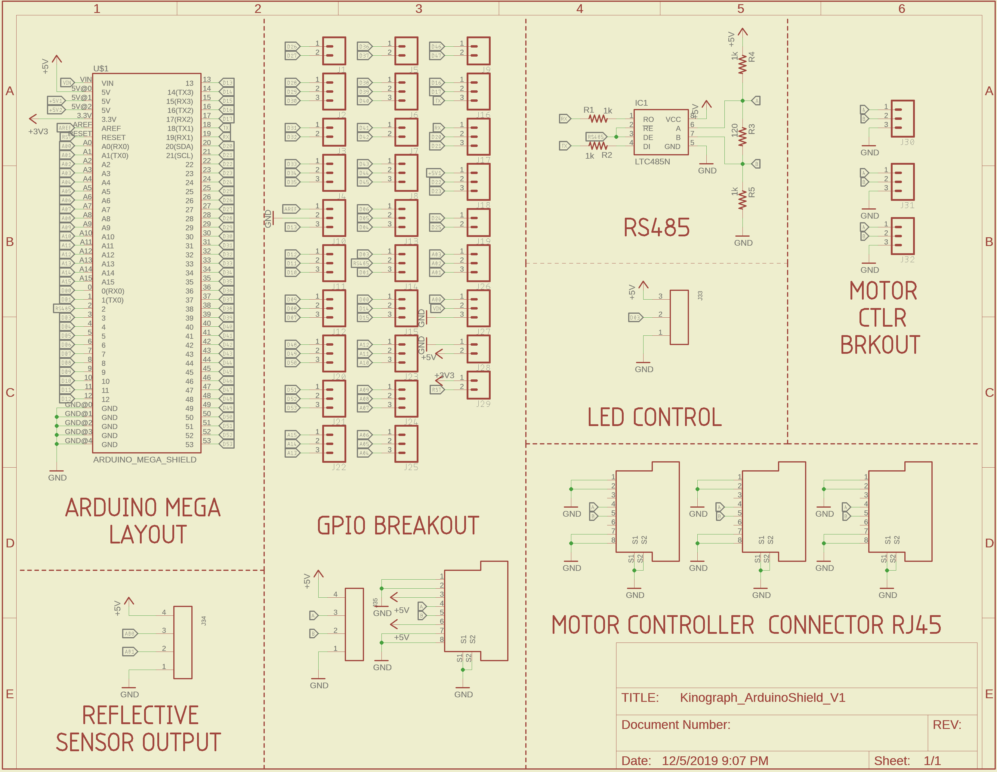
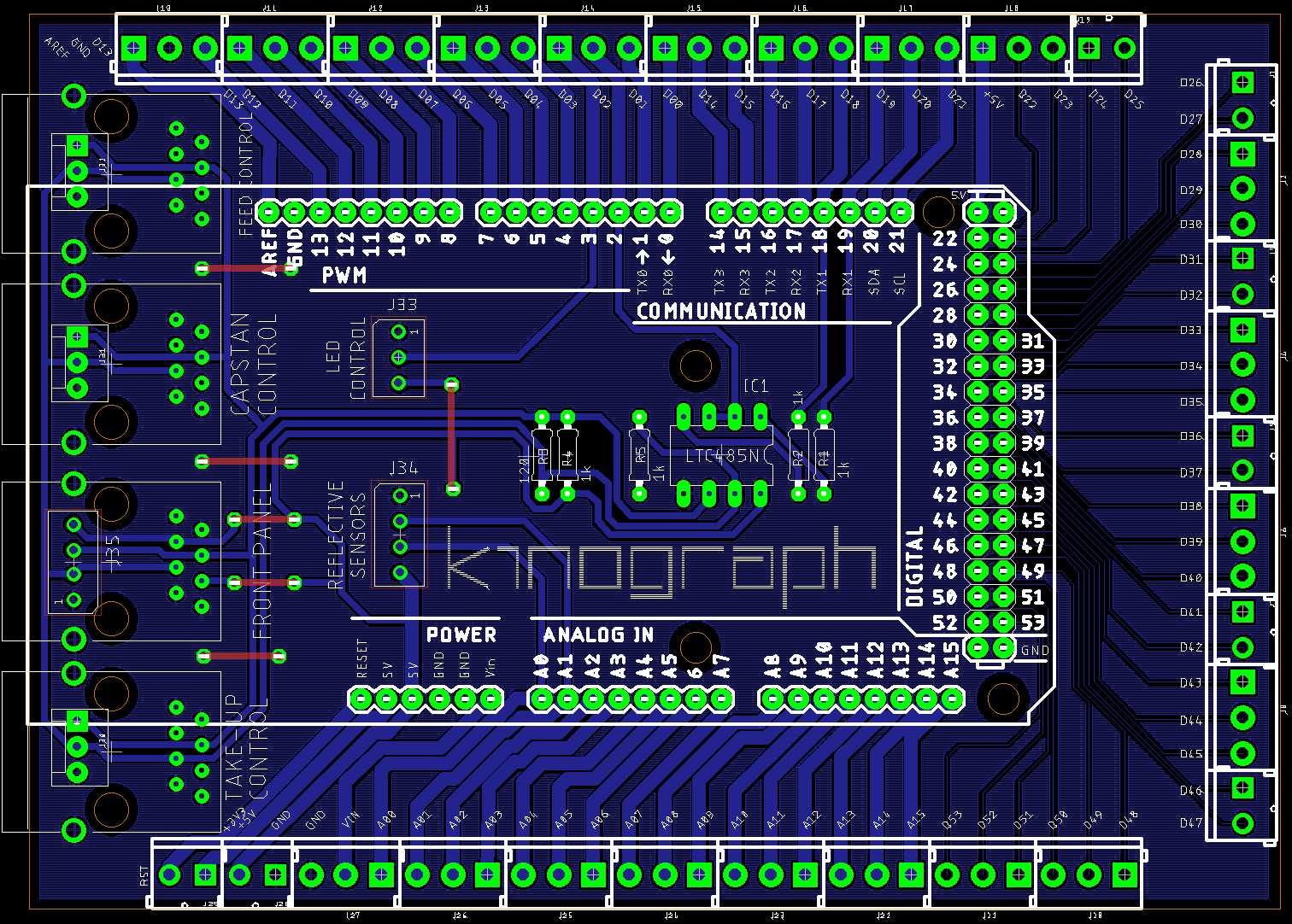
I hope to order the first prototype boards next week!

Hi all. Quick update here. Attached are new files for the PCB.

]PCB Layout
Schematic sheet

A few new thoughts. I’ve been looking into the torque motors that @friolator has on his 70mm scanning machine and I’m thinking this might be a good route to try. If it works, we can do away with these PCBs and save on a lot of time and headache. But I don’t have time to test all of that right now, so we’re sticking to this for the meantime.

As a quick reminder, these PCBs include the following:

  • motor driver
  • power hookup for motor
  • microcontroller for reading tension hub and managing feedback loop to motor
  • data connections to “mother” board for comm via serial

The reason we broke these out from the mother board was for modularity and simplicity of cabling.

And the reason we decided to go with manufactured PCBs has been covered above.

Everything will likely change, as it always does. But with this we get what has already proved to work fairly well in a package much easier to install.

Onward.

I think it’s smart to use RJ45 for your interconnects. We did that on the Imagica rebuild a few years ago: twisted pair is naturally noise resistant and they’re relatively thin and easy to route cables. If you need to break them out to screw posts, you can do so with very inexpensive DIN-rail mounted units like this one

We’re using DIN rails inside our 70mm scanner for mounting all the power supplies, and will be using RJ45 interconnects between things where necessary, using these kinds of breakouts. It makes things very neat and flexible.

On the Imagica, I had a board made to break out the arduino mega to a bank of RJ45s. it wasn’t a shield (though it could have been) but it allowed you to jumper pins on the arduino to pins on the breakout, then route nice neat cables from there to wherever. all of that would have been mounted inside a 1U rackmount enclosure, but I never got around to that part.

2 Likes

Hi all. Some snazzy PCB pics for you. These are the first boards to come back from the manufacturer. They were populated by Brooklyn Research after receiving the blanks.

1 - tension hub / motor controller (we have two of these, one for each side)
2 - main control panel
3 - Arduino shield (I’m already thinking of upgrading to a Teensy4 but alas, too late for this round)

3 Likes

Hi all,

I spoke with the contractors this week and as you may have noticed, we have not hit our first major deadline (Feb 1st). Here are the things we are working on and which we hope to have done in a couple of weeks (forgive the cross-posting for Milestone 2):

Arduino Shield:

Code: 

    Finalize protocol.

    Integration of all functionality together.

PCB To Do:

    Include LEDs on the front of the shield for visual feedback.

    Include longer Male Headers in the BOM

Motor Controller:

Code To Do:

    Finalize protocol

PCB To Do:

    Fix reverse polarity issues

    Fix reset-able fuse issues

    Change of the FAULT LED

    Breakout unused pins

Front Panel:

Code To Do:

    Finalize protocol

PCB To Do:

    Separate Mains Power Switch

    Fix 7 Segment Display issues

Capstan Motor Controller:

Code To Do:

    Finalize Protocol 

PCB To Do:

    Design Board for next phase  (if necessary).

Reflective Sensors:

Physical To Do:

    Attach mount to system (once new gate is installed).

Gate Light:

Physical To Do:

    Finalize mount system for sourced LEDs.

    Source different LEDs if necessary

Camera:

To Do:

    Capture tests with new gate

    Reflective sensor tests with new gate, mount, and speed control

    USB Throughput tests

    OpenCV analysis on captured images/video