[v2 dev] Milestone 3 - Lighting

In case is useful, I used as a light source a DIY array of LEDs by folding the led strips to reduce the spacing. Some of the LED strips provide a good light spectrum and these are bright enough. Please note that this was for an 8mm frame-by-frame scanner. I used a piece of plastic as a diffuser and the results were great. The metal behind is in the form of a fork, so additional rows can be added if needed.

That design looks great, I’ve really got to give you props on the gate, taking advantage of the flexibility of PLA for a compliant mechanism is a nice move!

What has your experience been like in calibrating the intensity of the LEDs? Are you adjusting the total output with a color meter or using a target with your imager?

Congrats on the awesome design! I really like what you’ve done with the sphere. And the printed springs on the sides of the film path in the gate is genius! Thanks so much for sharing.

What LEDs are you using?

@johnarthurkelly @matthewepler

The short answer: the LEDs I am using are from the Osram Oslon 10 mm Square type, about 1W power. You can purchase them in various wavelengths and I tried out different combinations. I am still in the process of optimizing them (more on this later in this post), but here are the ones I currently use:

blue channel: “blue”, wavelength 470 nm
green channel: “green”, wavelength 538 nm
red channel: “red”, wavelength 623 nm

I tried other, more extreme wavelengths, for example “hyper-red” = 660 nm for the red channel, but got mixed results depending on the film stock and Super-8 camera used.

The reason is the (complex) interaction between the response curve of the film stock, the response curve of the camera and the small band of wavelengths a single color LED is actually sampling. The old film stock was optimized for projection by the continous spectrum created by the projection lamp, and any single color LED samples just a tiny part of that spectrum. So during experiments, with one film stock/LED combination, the outline of the daylight filter of the camera showed up in scans as a faint red shadow around the perimeter of the image. Switching to another red wavelength solved this problem.

On the other hand, turning to “white light” LEDs did not solve my problem either, as their spectra are typically very different from a classical light bulb. They usually have a big power spike in the blue color range. Also, I wanted to be able to adjust the color temperature of the light source. So I stayed with the separate LED setup.

Well, the above mentioned wavelength-combination gives me currently the best results, but I am still optimizing on that point.

Initially, I started out with a larger integrating sphere which was easier to design, but the power output was not sufficient. Reducing the diameter to 50 mm solved this. I am able to image the darkest shadows of Kodachrome 25 film stock with an exposure setting of 1/32 sec @ ISO 100. The camera I am using is a standard Raspberry Pi v1-camera. (I tried other camera setups, but this turned out to be the best option for me so far - long story…:slight_smile:)

With respect to the color balance: I am using a fixed color-balance on the camera, as the Raspberry Pi camera (or rather the processing pipeline on the Raspberry) has some issues with highly saturated colors (think of a bright blue sky on Kodachrome for example).

To calibrate the LEDs, the image of the empty film gate is used in conjunction with a histogram display. Here’s how that looks in my software:

On the top, there are three sliders for the power of the color channels. Before adjustment of the color balance the exposure time of the camera is reduced so that the film gates intensities are within the histogram display range. Then the three color sliders are moved until the curves in the histogram (bottom part) overlap optimally. In the situation captured above, I still would reduce the power in the red and blue channel a little bit, until all color curves overlap perfectly.

I am actually able to switch the camera into raw-mode to do this with the four raw color channels (R/G1/G2/B). But, normally, just the usual RGB-stream is sufficient and substantially faster to adjust than the raw camera stream. The LEDs need some time to heat up, about 15 min is usually sufficient.

That is all the color adjustment I am currently using. I can get away with this because my whole image processing is done in HDR-space, so I have plenty of headroom to adjust for good color in the post-processing pipeline.

Film capturing typically consists in my setup of taking 5 exposures of each film frame, ranging from 1/1000 sec (full intensity of the film gate maps to a bright “white”) to 1/32 sec (even the darkest shadows of Kodachrome 25 film stock show structure in this image, most other stuff is grossly overexposed). These 5 exposures for each frame are stored on disk for later processing (which consists of: exposure fusion/sprocket registration/cropping/gamma adjustments/color grading).

Another approach to color balancing that worked for me is to adjust the LED powers directly to the material at hand. Super-8 film stock (Kodak/Fuij/Agfa/etc) is very different, colorwise. But one can adjust the LED color balance directly to the film stock at hand, provided some part of a frame can be identified as pure gray/white surface.

However: that approach is very difficult and unreliable if you have no good reference of a colorless surface.

For some Super-8 movies I made in the 80s I actually filmed a color chart at the beginning of the filming - never did I expect that this would turn out to be helpful nearly 40 years later!

1 Like

… here’s an example of a frame capture to illustrate the above description.

Top left is the frame capture with 1/1000 sec @ ISO 100. The sprocket hole is not burned out and appears white. This is how the LED power was adjusted. Dark shadows show no image structure, as the camera can not capture the high dynamic range of the film stock.

Top right is the frame capture with 1/32 sec @ ISO 100. Almost all of the image is burned out, except the dark shadows. Currently, I take a total of 5 exposures. The best single exposure image of this image stack is the following image:

For my taste, the structure of the bright stone floor is burned out to much in this image and the details in the shadow are fading too much in the darkness. That is why I decided against a single image capture and instead utilize intermediate frame motion which allows me to capture an image stack with different exposure settings for each frame.

The stack of 5 exposures is combined via exposure fusion, which result in the HDR image in the lower left corner of the top image (strictly speaking, this is not a true HDR - but this is another topic). Here, the contrast of the HDR image is reduced so all of the image detail is visible.

The HDR image is further processed into the final output image. Processing consists mainly of contrast adjustment, gamma-adjustment and sharpening. The final output picture is displayed in the lower right corner of the top image.

If you compare closely one of the input images with the output image, you will notice that a slight color shift was introduced. Therefore, the color of the sprocket hole is no longer pure white. Color correction and color grading are two close cousins…

2 Likes

… and here are some further infos about the integrating sphere implementation:

The inital integrating sphere was designed with nearly double the diameter (d = 98 mm) than the final setup (d = 50 mm), because I really wanted to stay below the 5% limit for the total port area. Here’s a photo of this intial setup:

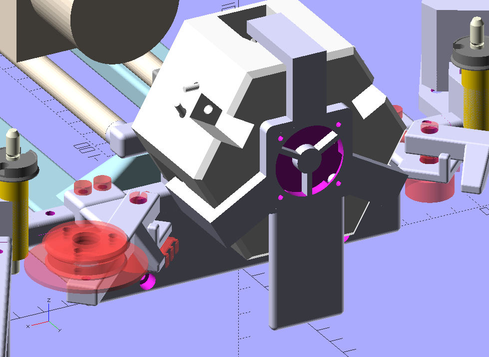
The unit was split into two halfs for easy printing. Three entry ports were used for the LEDs which were mounted on a rather large heat sink. These heat sinks were kept outside of the unit in free air. So LED-temperatures were no issue in this design. The next image

shows the internals of the second major iteration. Note the three baffles placed around the hole of the film gate. These baffles turned out to be important, as they block any direct light coming straight from the LEDs. Without the baffles, illumination of the film gate was uneven, in terms of color constancy.

The form of the baffles was calculated in such a way that they have the minimal surface necessary to block direct light from the LEDs (compare the size and shape of one of the baffles shadow with the film gate).

This design had the further advantage that you could easily replace or change the LEDs. However, the illumination levels where not really satisfactory. Using several LEDs mounted on a single heat sink was one option I tried, among others. Finally I settled for a different, much smaller form factor for the integating sphere, as well as the LEDs:

Left in the image above you can see the old, large design with external heat sink. A multicolor LED is fitted into the mounting tube of this old design. In the right half of the image you can see the type of heat sink/LED I am currently. The LED is an Osram Oslon SL 80 LED mounted on a small heat sink with dimensions 10 x 10 x 10 mm.

The most important change of the third design was a diameter of the integrationg sphere about half the size of the original design. This increased the illumination intensity by nearly a factor of four. Furthermore, the mounting of the LEDs was changed. They were placed way deeper and tilted in the unit. Therefore, the original baffles around the film gate in the original design were no longer needed and could be replaced by small tongues near the mounting holes of the LEDs (cmp. the illustration a few posts above).

As it turned out, the heat sinks alone were not sufficient to keep the LEDs cool enough, so an active cooling system with a fan in the back of the unit and corresponding airducts to the LED heat sinks was added:

This current setup performs ok so far. Temperatures of the LEDs stabilize to about 50°C, even if the unit is operated for days.

One disadvantage of my lastest design is that changing or replacing a LED requires the whole unit to be unmounted and opened.

By the way - I remember much simpler designs based on the “integrating sphere” idea. For example, in the 80s I owned a color enlarger that did use a simple cube-like box for light mixing. On the bottom of the box was a glass plate for the 6x6 cm film format. The other walls of the box were covered simply with styrofoam. The light of three adjustable color filters was shining through a small hole in one of the sides of the cube onto the opposite side of the cube, but not directly into the film gate. The performance of this simple setup was quite good.

3 Likes

This is excellent documentation, @cpixip. Thank you for all the time it took to walk us through the design choices you made. I think this is going to be extremely helpful when we get to lighting design in early 2020.

Not counting the 3D printing, what would you estimate the production cost to be in terms of materials and time to assemble?

Also, that software you are using looks great. Did you find that somewhere or write it yourself?

I really love the detailled description of the evolution of your integrating sphere, cpixip! For comparison here is the lighting setup of the Wolverine:

Not quite as elaborate, but quite effective for the small size and provides fairly even lighting for the tiny light table. The LEDs feed into the relatively thick diffuser plate at a 90 deg angle. Because of the shape of the diffuser, direct light is almost guaranteed to get reflected by the surface instead of passing through. What the diffuser is really made of, I can’t easily tell. It’s littered with dots that look to be at different depths of the material.

1 Like

This is great. Thanks for the teardown, @mbaur!

@cpixip I was mulling over your design a bit more and was wondering a few things:

Did you notice any difference in running temp on the different LEDs? Like the top one staying cooler because the hot air having an easy way out? If so, how about setting the baffles or tongues at 60 degrees instead of 120 effectively putting all the lighting sources on the top half? And to avoid direct light from the LED maybe try adding a slight angle of the LED openings toward the front? That way the LED would be “aimed” more towards the back of the sphere away from opening where the light exits.

And the second question I thought about was the surface: Have you tried reflective spray paint to coat the inside of your sphere? There might be some rattle can paints that could work.

And thank you so much for publishing your whole design evolution. Especially the steps that didn’t work so well are very helpful in knowing what not to try :slight_smile:

… well, the 3D printing takes about 2 days on my printer, which is a cheap Anet A8 (200 €).

Add about half an hour of spray-painting the inner side of the sphere. Assembly is rather simple and might be done in a few hours. You take the 3 LEDs with their squared PCB and solder wires to the pads of the PCB. Then an adhesive pad is used to glue the LED-PCB and the heat sink together. I guess you will need at most an hour for this task. The next step is to insert the LED together with the supply wires into the grooves of a half unit.

This cut-away rendering shows how this done (I hope :slight_smile:). The straight dark red lines are the wires:

Once that is done, the back and front halfs of the unit are pushed together. There’s a rim on one half and a corresponding grove on the other half, so some sort of snap-fit is achieved. Just to be sure, 3 long M3-screws are used (on the bottom part of the above cut, you can see the channel of these screws). All that doesn’t take too much time and that is the final assembly step.

With respect to costs: each LED-unit is composed of

  • one Osram LED on a 10x10 mm square PCB, about 3 € (I am in Europe)
  • heat conducting pad, about 10 cents
  • 10 x 10 x 10 mm heat sink, about 1 €

So that would be about 4 € per LED-unit, so a total of 12 € for the LEDs. PLA-material for printing the sphere is negligible, probably less than a 2 €, while printing time is not (2x days with my printer).

The real costs are probably hidden in the electronics which drive the LEDs - these are programmable constant current sources. For my setup, I did not want to use PWM-type of LED-dimming (which usual LED-strips do).

However, I can’t really give an estimate on these costs, since I used parts I had already available. Basically, the electronics consists of two dual DAC (10 bit resolution, SPI-interface), a quad operational amplifier and 4 power fets on heat sinks. Part costs might be around 30 €, at most. I created a first (through-hole) version of a PCB for this unit, but that circuit design still needs some improvements.

Which brings me to your second question, the software. I do develop my own software. As my system splits the work onto three processors, it depends a little bit on the processor which software environment I am using.

First, there’s an Arduino Nano which drives four stepper motors, reads potentiometer values from two tension control arms and adjust the LED-currents to the requested values. This part of the software uses the Arduino-IDE (so essentially C++).

The Arduino gets its commands via a serial interface from a Raspberry Pi 4. Connected to this Raspberry Pi is also the camera used to scan the film. It features a v1-sensor chip and a Schneider Componon-S 50mm as lens. Both camera and serial communication with the Arduino are handled by a server running on the Raspberry Pi, written in plain Python 3.6.

This setup is very similar to other people which utilized a Raspberry Pi for telecine. A special library which is utilzed in the server software is the “picamera”-library. The server is able to stream low-res images (800x600) @ 38 fps, but drops down to a few frames per second for the highest resolution and color definition.

Anyway, I do use a special version of the picamera library, which is able to handle lens shading compensation. This is absolutely necessary if - as I did - you change the lens of the camera (remark: via lens shading compensation, a partial compensation of color shifts can be achieved which are introduced by a lens change. Turned out to be sufficient for my needs in case of the (older) v1-camera. The newer v2-cameras become unusable if you change the lens).

Well, the Raspberry Pi server delivers a camera stream plus additional camera data to a client software which is running on a rather fast Win10 machine. This software is also written in Python 3.6 and uses a few additional libraries. Specifically,

  • Qt-bindings (PyQt5) for the graphical user interface
  • pyqtgraph for graphical displays like histogram and vectorscope
  • cv2 for a lot of image processing
  • and finally numpy for the rest

This client software can request an exposure stack from the Raspberry Pi and essentially stores the original .jpg-files of the Raspberry Pi camera on disk for later processing.

The next piece of software is a simple Python script which does the exposure fusion (Exposure Fusion). While cv2 has its own implementation, I actually opted to implement this by myself in order to have more control over the internal workings. This script takes different exposures of the same frame and combines them into a single intermediate, stored again as 48-bit RGB image on disk.

Note that this exposure-fused image is not a real HDR-image. Actually, the client software mentioned above has the subroutines available to calculate real HDR imagery (which consists of estimating the gain-curves for the camera, and than combine the exposure stack into a real HDR-image), but I did not find a satisfactory way to tone-map the resulting HDR-movie into a normal 24bit RGB-stream. So I settled with the exposure-fusion algorithm of Mertens.

Anyway, the 48-bit pseudo-HDR images are than read by my third piece of software, also written in Python 3.6 + PyQt5 + pyqtgraph + cv2 + numpy, which allows me to do sprocket registration and various color and other adjustments. Here’s a screenshot of this program to give you some idea:

The 48-bit intermediate image can be seen in the top-right corner of the frame display for reference. At this point in time, the software works stable, albeit a little bit slow. Also, too much experiments left their traces in the code. So I am planning a total rewrite of this software once I think it has reached its final form…:wink:

@mbaur: this teardown is interesting! Because: this setup is very similar to illumination setups used in LCD-screens (edge-lid backlights). The white dots which are visible are used to “extract” the light from the sideways placed LEDs perpendicular into the surface to be illuminated. Sometimes (in LCDs), these dots do vary slightly across the surface to counterbalance the otherwise uneven light distribution of such an setup. So actually, ripping apart an old LCD screen to get the diffusor might be an interesting basis for some experiments with a brand new telecine lamp! :joy:

1 Like

I used to work for a company that designed and built integrating-sphere light sources. The very fragile Barium Sulfate was typically replaced by Spectralon, a trademarked form of PTFE (Teflon). In this case the sphere was made from a block of that material. It did not just reflect at its surface, but through the volume of the material. So wall thickness had to be kept high.

There were specialty sources for which we used good old fashioned Krylon 1502 Flat White spray paint. We had to use a surface scatterer, because we were working with very short laser pulses that would get stretched by passage through the spectralon. The pulse spreading just due to the integration sphere geometry was much less (the spheres were quite small). But not an issue in the Kinograph application anyway.
Why is it that you, @cpixip can’t use PWM LEDs? Is there an exposure effect due to too-low a frequency driving the modulation?
Also, the 5% opening diameter was sometimes violated (by a lot) without noticeable non-uniformity.

@mbaur:

Did you notice any difference in running temp on the different LEDs? Like the top one staying cooler because the hot air having an easy way out?

No, not really. After adding the airducts, the temperature of the LEDs were quite similar, within a few degrees Celsius. There was a larger difference without the active cooling, exactly as you have described above. Note that the LEDs are driven with slightly different currents as they have different efficiencies. Typical values are 294.7 mA (red LED), 425 mA (green LED) and 278.5 mA (blue LED). That results also in slightly different temperatures by itself. The cooling with the little fan (it is a 5V fan used by Raspberry Pi units) is quite effective.

If so, how about setting the baffles or tongues at 60 degrees instead of 120 effectively putting all the lighting sources on the top half?

That could probably be done by going back to the original design were the wires and heat sinks are kept out of the unit. The current design holds the LEDs mainly in place by the supply wires. These wires are running through straigth channels in the body of the integrating sphere. Easy mounting, but you also have to dismantle the unit if you want to replace a LED…

And to avoid direct light from the LED maybe try adding a slight angle of the LED openings toward the front? That way the LED would be “aimed” more towards the back of the sphere away from opening where the light exits.

This is actually the current design (have a look the cut-away drawing I posted above). The LEDs are tilted by 45° and the baffles are now just small tongues close to the LEDs which also act as fixation points.

And the second question I thought about was the surface: Have you tried reflective spray paint to coat the inside of your sphere? There might be some rattle can paints that could work.

No, I have not tried any other spray paints. I have printed the second version with black PLA, in order to reduce the light shining through the unit, but that did not help too much. From the theory of the integrating sphere, you do not want to have highly reflecting surfaces. Ideally, the surface should be “ideally dull” (more technical: it should have a Lambertian reflectance function). Barium sulfate is a material which comes close to this. I used simply several coats of white radiator paint. That is far from ideal, but currently sufficient for my setup (it mixes the light from the LEDs ok and the exposure times are short enough that I can work with them).

@bwrich:

Why is it that you, @cpixip can’t use PWM LEDs? Is there an exposure effect due to too-low a frequency driving the modulation?

At least that was what I was afraid of. The camera I am using, a standard Raspberry Pi camera, is a rolling shutter camera. I was afraid if I would use pulsed LEDs, the intensity variation of the LEDs might show up as bright and dark horizontal stripes in the images I am taking. Or at least as some sort of color/intensity noise.

Of course, a high enough PWM frequency would certainly take care of any such effects. But I am not sure how high such a frequency would need to be. I think WS2812 LEDs for example work with 800kHz typically. Given, this would result in 800 pulses during a single exposure time of 1/1000 sec. Probably enough pulses averaged during that exposure time to avoid any negative effects on image quality.

For me it was easier to use constant current sources, as I had the parts already available.

An additional comment: my decision to not use PWM was done years ago, and I can not really remember the research I did at that time.

Anyway, trying to clarify some points a little bit more, I discovered that the RGB-Led I cited in the first reply of your question, the WS2812 LED, seems to have only a PWM-frequency of 400 Hz, not the 800KHz I mentioned above - that is the frequncy these units can communicate with. Now 400 Hz is way to low not to show up as intensity stripes during short exposure times.

The troubles you can come into with PWM’ed LEDs is well-known, see for example this video Oh Come All Ye Faithful LED Fix Comparison where a recording suffering from PWM is fixed. Also, this short article here LED Color Shift Under PWM Dimming discusses other issues related to PWM’ed LED setups.

Things like this pushed me into my decision to use constant current sources for driving the LEDs, just to be on the save side.

2 Likes

@cpixip I am doing some improvements to light source for the second round of a frame-by-frame 8mm/super 8mm DIY.

First and foremost, I have no clue on what are the particulars for best light source. I did some experimenting using a circular polarizer placing it in various locations and comparing, and had some interesting (and some puzzling) results. The setup is light source - film - inverted Nikor 50mm F2.8 - below - DSLR Nikon D3200.
When the polarize was set between the light source and the film, there seem to be an slight improvement in details (dust/scratches) and the grain seems less prominent. In other locations, the grain seemed to improve at the expense of less details. To say that the changes were subtle is an understatement… but given my clueless approach, would like to ask if you have any experience before I chase the rabit down this rabit hole.
Thank you

Interesting - were you by any chance using pairs of polarizers? Or was it just the one circular polarizer placed between the light source and the film?

The Callier Effect has more to do with collimation but it’s possible a similar effect could be observed with polarized light… you could also have a well-collimated light source and I just don’t know about it :slight_smile:

Only a single circular polarizer. Do not have a linear polarizer, although thinking about getting a linear film to do more testing.
Definitely do not have a well collimated source.

If you introduce polarizers into your imaging pathway, be aware that there iexists the so-called photoelastic effect. Many translucent plastics show stress birefringence and you can make colorful images of the stress distribution in a sheet of plastic with polarizers.

With respect to “optimal” LEDs: I actually tried to approach that issue somewhat scientifically, and calculated the transfer functions of my intended “LED->film->camera” setup. To do so, you need the emission spectra of the LEDs, the transmission spectra of the film stock you are working with, and finally the spectral response curve of camera chip you are using. Needless to say, it is quite difficult to get hold of such data.

I did the calculations anyway and came up with an “optimized” setup. However, as it turned out, this setup was far from optimal. For example, the RED LED was way too far emitting in the infrared and the scanner picked up and amplified uneven exposure of film stock which I did not see in a normal projection of the same movie.

So in the end, I simply tried out different sets of LEDs until I got something workable for me (details are noted above somewhere). It seems to depends only slightly on the film stock, much more on the camera and how its internal color calculations work. Also of course on the design of the illumination system. I opted (as detailed above) for a very diffuse one - it reduces the amount of scratches you are going to pick up. But, as @johnarthurkelly already noted, it reduces image contrast…

It’d be very interesting to see the work you’ve done calculating the transfer functions for your setup @cpixip!

Would you mind sharing your camera and lens setup as well? I believe this information could help shed some light on the concept of the imaging chain/system for other group members.

@PM490 @cpixip I actually think both of you would find this paper interesting:

Optical Detection of Dust and Scratches on Photographic Film