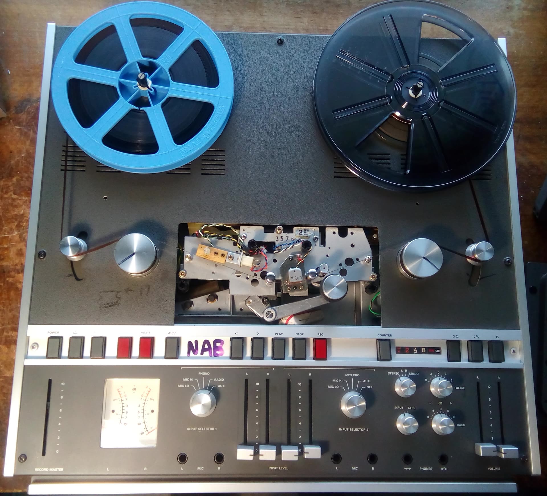
My first post here I think. Here are photos of adaptions I made 3 years ago to an existing Revox A700 semi pro tape machine for high quality 8mm sound strip playback. The A700 lends itself to such mods because it has 1. Easily swappable tape head blocks. I adapted a spare tape headblock to 8mm film and soundstripes (both main and balance stripe on Super 8mm, and the single stripe on regular 8mm). 2. 10.5" reel capacity, more than large enough for the largest usual 8mm reel. 3. Electronic servo tape/film tensioning, allowing film tension alone to press the film against the read head, (which all good pro 8mm film scanners with sound would or should have) as opposed to the cheap plastic fingers pressing the film against the head as in even the most expensive consumer 8mm projectors. Much better stripe to head contact than the plastic fingers, resulting in much reduced wear of the rare 8mm sound stripe heads. 8mm consumer sound projectors are brutal on the sound head, which is why so often the sound playback is muddied and hissy 3. Vari speed of the film playback speed. 4. Very low hum levels due to the proper design of the Revox A700 machine for which of course I can claim no credit.
This is a work in progress. A proper synchronisation system is still to be completed and I’d appreciate any comments from others with more expertise in this area.

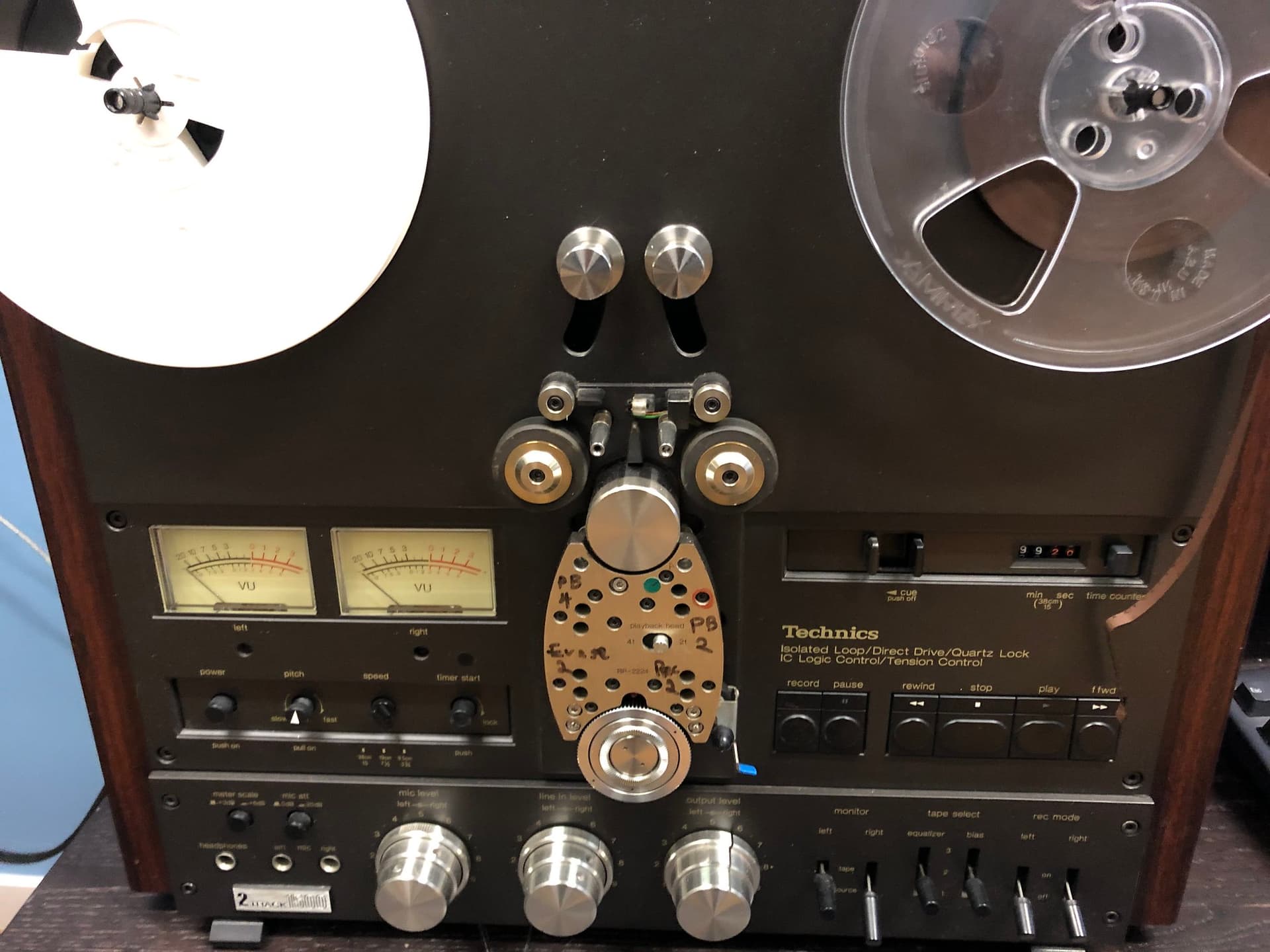
Interesting. We have a modded Technics 1/4" deck that was done by Super 8 Sound back in the day, to play fullcoat S8 mag tape. This is Super 8 film that has no picture, it’s all audio, used for double system editing of picture and sound. They made two or three portable systems, based on different decks (some Uher, some Sony), and the track position varies from portable to portable. And then they made some larger studio machines that can take big reels, like ours. The technics allows you to choose which head you want, and has adjustments to fine-tune the head position to maximize coverage.
To keep sync, they added a perf sensor, which presumably sends a pulse to an external resolver. That in turn sends signals to the servos in the deck to adjust speed. This is similar to what’s done on a Nagra and other 1/4" decks, but instead of a perf sensor, they use a recorded 50Hz or 60Hz pilot tone signal on a separate track (or with Nagra’s Neopilot, two out of phase pilot tones that cancel each other out on playback). In any case, the basic idea is the same - a resolver detects the speed variation using the reference signal, and adjusts the playback speed on the fly to correct for speed changes.
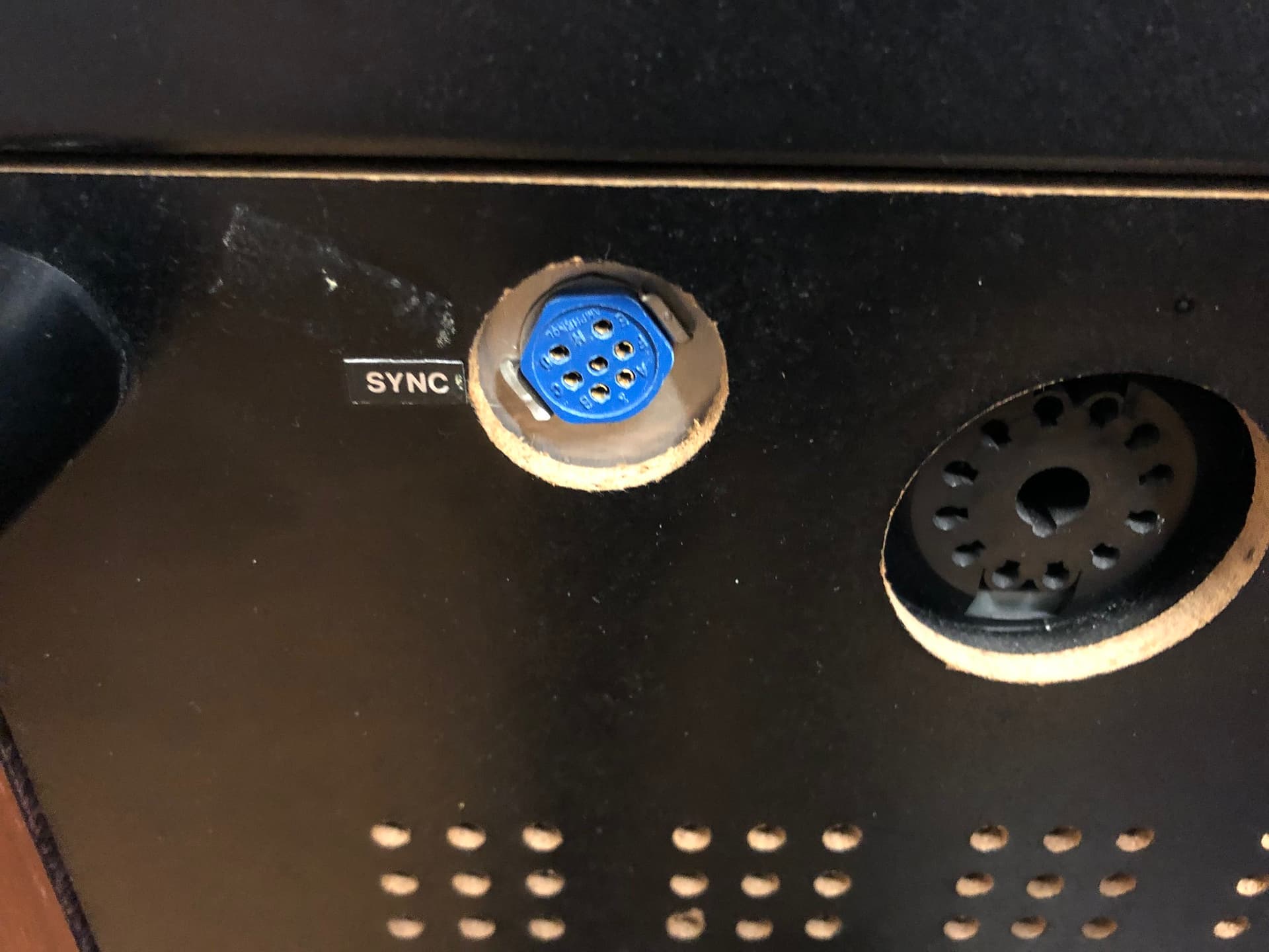
We don’t have the resolver for ours and there is no documentation available. Most of the people who designed these machines are long gone, and I’ve been unable to get good information from the folks who sold them, so I’m very curious how you go about doing this. Eventually I want to start probing the mystery “Sync” port on the back of the machine to see if I can figure out which pin does what. But controlling the servos like this is well beyond my skill set…
Thanks for the info. I didnt know Super 8 Sound modded those Technics decks but I have a standard Sony TC-800 portable which I know was a model they converted for recording and playback of fullcoat with sync. I once temporarily modded it to play fullcoat tapes but had no real use for that so returned it to standard.
For some reason the second photo of the A700 didnt upload correctly so trying another upload.
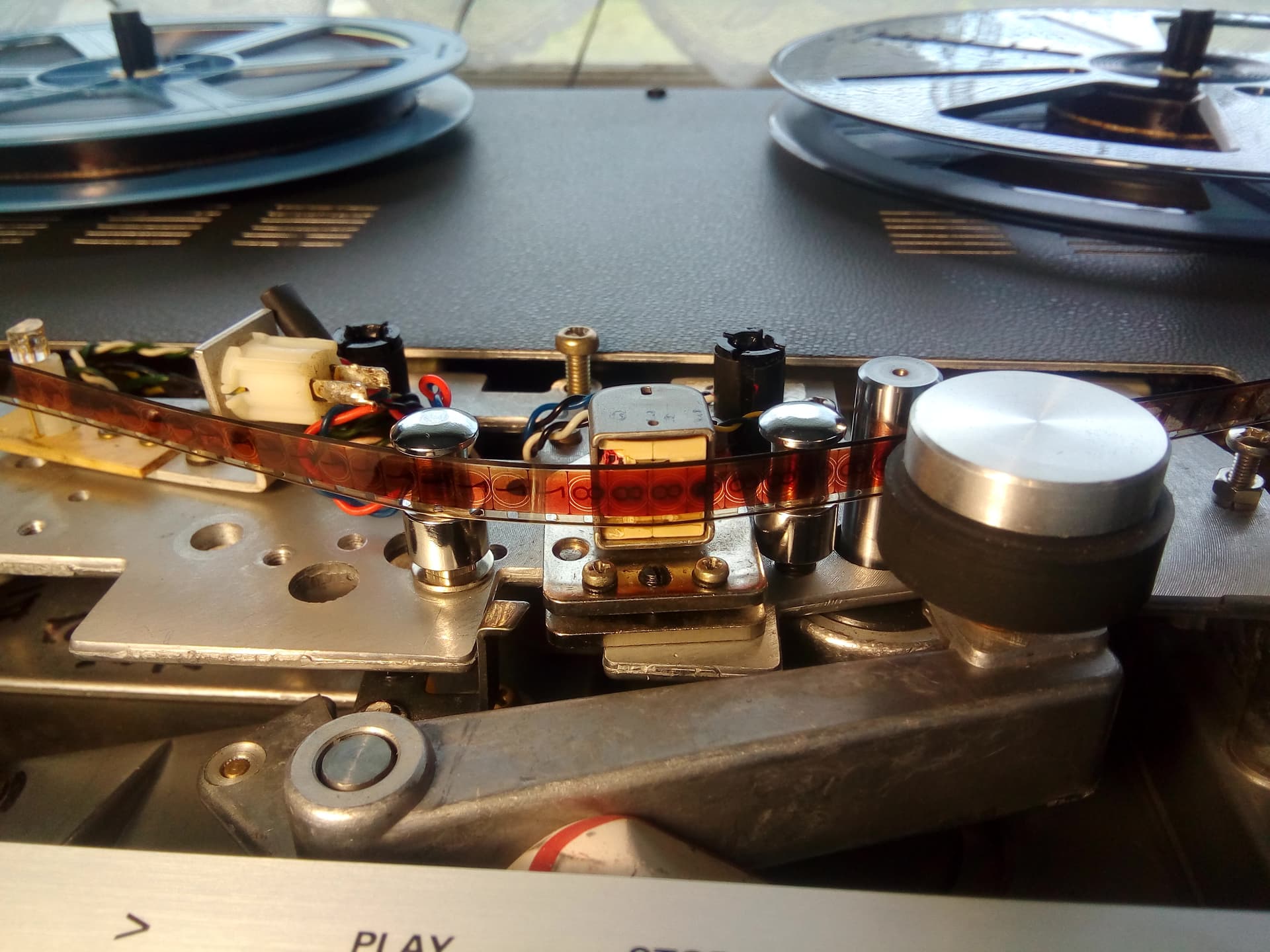
Notice the rotating aluminium film guides which I retrieved from an old mag striping machine and modded to fit the A 700.
Since the photo I’ve experimented with a perf sensor for a sync reference signal recorded parallel with the audio. An improvement may be a Keyence lightpin arrangement.
Cool. If you look through their old catalogs there were a few studio models they sold over the years. The company was an MIT offshoot, and a lot of what they did was about tinkering with S8 gear to work (kind of) like 16mm.
How did you keep sync with that machine, or did you?
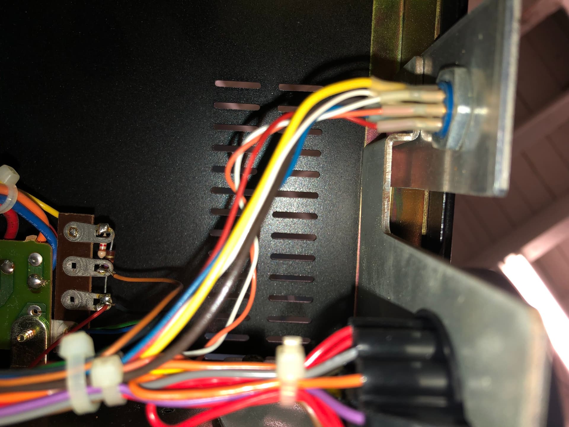
I know nothing about how the servos work in our Technics. I’m sure I can figure out which pins are outputting the perf sensor pulses with an oscilloscope, and from that could code something (arduino or pi) that responds accordingly to control the servos. I just have absolutely no idea what the servos are expecting (or if it’s even the servos themselves one is directly controlling, or if there’s some other board buried inside the machine that Super 8 Sound installed.
I’ve made up a simple perf sensor using an off the shelf transmissive sensor but havent gone much further. Interfacing the “control track pulses” with the capstan motor is one way but I know the electronics has to be done very well as it was in VHS VCR’s. Another would be converting the perf signal into something recognized by software for “stretch and shrink” on the audio track. I need to hit the books more as you say.
But for me the main advantage of the exercise apart from protection of the fragile film and stripe itself, is better fidelity to the recorded sound on the stripes. So we need a reference. Probably the best of the Super 8 consumer sound projectors are the Elmo’s but unless they’re maintained, the performance can easily deteriorate. I wonder how many have heard good 8mm mag stripe sound played back at its best, as that reference. Hearing a good reference playback might help some realize the fidelity problem is not so much in the format as their playback of that format.
Not quite “reference standard” but here’s a short YT vid I just made demonstrating what even the humble Super 8 magnetic “balance stripe” can sound like when played back well. Hope you like it.
I did some machine repairs long ago. In VCRs/VTRs the control track is especially critical, since the video head alignment is dependent of it.
Some analog alternatives are to design an analog phase-locked-loop (which is not trivial, and I believe what a typical VTR uses) or a more amicable pwm to DC circuit. A sample and hold of an integrating ramp would be very precise. The sample and hold uses the perforating pulse to reset an integrating circuit (a ramp) and the hold keeps the ramp voltage before is reset.
One edge of the pulse can reset a 16 bit counter, and it will provide a precise period. For the output, a DAC (probably 16 bit too) can then be used to provide the control output to the servo. When the period is lower/higher than the set period, the output would increase/decrease accordingly. This should be doable as long as the counter and register have enough resolution, my guess is that 16 bit would be a must.
If the 16 bit DAC is not handy, a 16 bit PWM output can be an alternative, with a low-pass RC to convert to DC. For a clean DC output, the response time would be a bit slow, but it should work too. I used it to control the constant-current driver, and this posting has relevant references for the PWM workaround to get 16 bit out of an Uno.
I’m impressed you’re able to get that kind of range out of such a small track, but was that recorded with the Sony deck? Most balance track recordings were done on projectors and some of the late model motorized editors (Elmo made the one I used in college, I think) and sound like it!
I dont know exactly what it was recorded on but not on my modified Revox A700 tape deck which can only play back the mag stripes. The main track on this film carried location sound. Probably back in the day, this music on the balance track was recorded on a stereo or perhaps dual track Super 8 sound projector, of which some of the better brands were Elmo, Bolex and others. I think Heurtier of France made an impressive stereo model sound projector, the Stereo 42 model, seen at the time as a sort of Rolls Royce of Super 8 sound projectors. Recordings on these projectors generally carried better sound quality than the projectors were capable of reproducing. Also such recordings back in the day were likely made on newish projectors capable of performing at their best. 40 or more years on it’s not so easy to find such a sound projector in top working condition. But I fully understand that for someone listening to this, for all they know the audio I presented could be a fake.
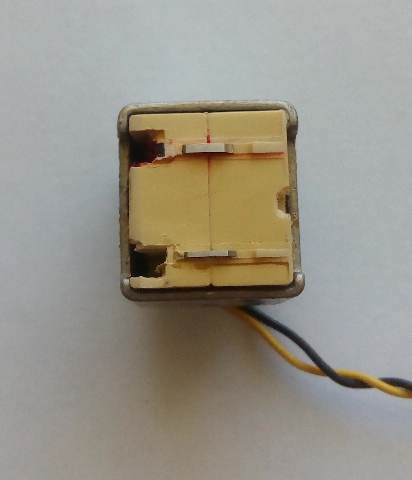
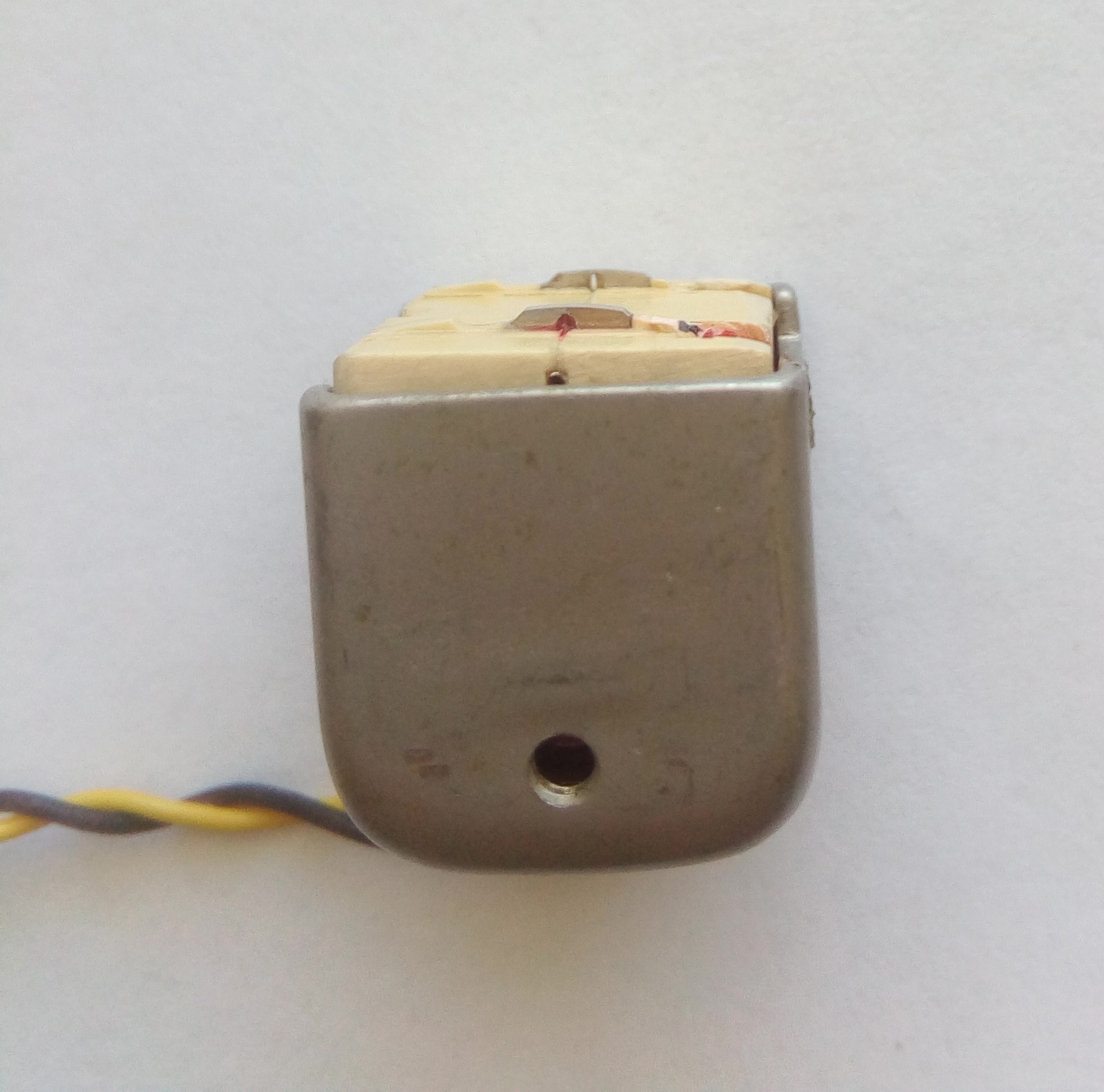
As per the photos the head is specially for 8mm sound stripe. The two protruding metal sections match the stripe width dimensions and only they touch the film. One is narrower than the other as per the magnetic stripes on the film. The yellow resin in between does not touch the film to avoid scratching the picture area. Apart from that the mag stripe head is pretty much the same as any tape recorder head. The two square dark areas would normally contain tiny integrated erase heads but as my application only requires playback, I removed them. I had to purchase this head as new old stock from Europe.
Thanks for the info. For someone not well traversed in the audio world, would it be possible to try to retrofit a tape head from for example a casette player, since those seems to be easier to get a hold on?
A cassette head would read the stripe but risk scratching the picture.
For this reason all good projectors and scanners including silent are designed only to handle the film by the edges. But also, reading an analog magnetic sound track requires running the film across the head at constant, smooth speed. Sound projectors had extra parts to help achieve this such as a heavy flywheel as in a cassette deck, or reel to reel, or VCR.
Dear @oldgoody1 , I have looked back at this post many many times.
Now I am thinking of trying to build one myself. The Revox A700 is not very common where I live and I was wondering If there are any specific requirements the open reel deck must meet to be compatible with your mod. I was thinking of modifying a Philips 45xx or a Sony TC deck.
On the subject of the audio head. What type/make/model was it and/or what model projector was it originally installed in/from?
Lastly, I only see two cables coming from the head. Is it stereo? Does it not need a ground? Would it be possible to wire it up to go straight to XLR?
Many thanks and Greetings!
My mods relate to the A700. I cant comment on the suitability of this mod to other tape machines except in general terms. An easily removeable headblock allows swapping from 1/4" tape to 8mm film duties, and back again, so much quicker. It’s mostly only pro or semi pro machines which have this feature.
You could mod. an existing 1/4" tape machine for 8mm mag striped film but reverting back to 1/4" would probably be messy and time consuming. So it would probably be best to make it just for 8mm mag stripe playback only, sacrificing 1/4" tape playback.
The key modification components for the A700 were the 8mm head and the four special 8mm guides.
The 8mm magnetic heads were sourced from a company in Europe. I ordered two heads. They sent me one mono head, and one stereo head which was an unexpected bonus. The one pictured is the mono head (only reads the main wider track) so only two leads. I think both heads were designed for Bauer 8mm projectors. Maybe Van Eck Video services have an 8mm mag stripe head as a spare part. Some 8mm film editor/viewers have a mag sound head attachment. That head might be suitable.
The film guides (two fixed and two rotating) were obtained from an old Australian 3-S 8mm film striping machine which I purchased online. The rotating guides needed modification to fit the existing A700 spindles. The film picture area must not scrape against the guides as does magnetic tape, or the picture will be scratched.
Thank you very much for your advice!
I will (as you suggested) be using a recorder that will permanently be used for this so it does not need to be reverted back to it’s original state.
Would you still happen to know which german company you sourced the heads from?
If you don’t it’s ok, I can always find a broken Bauer projector and use it’s sound head.
Again, thanks for the input!
I would do a search for “8mm magnetic sound head”. It doesnt have to be a Bauer head. Whichever head, you will need to custom adapt its mounting for the tape machine you fit it to. A head from a dual 8mm format sound projector is 2 track so can potentially work in stereo. I would look for a “new old stock” head as they can have worn down with use.