One of the steps in improving my build (original posting, needs updates) was to improve the quality of light. Somewhere in the process I became intrigued by the discussions on stacking algorithms, and given that I rely on DigicamControl for managing the camera, one simple way to do so would be to give the arduino the ability to control the light (for more info on the workflow see this post). The forum has a few postings on the struggles of controlling LEDs, so thought this posting would be helpful to all.
To dim by switching or to dim by changing current… that’s is the question
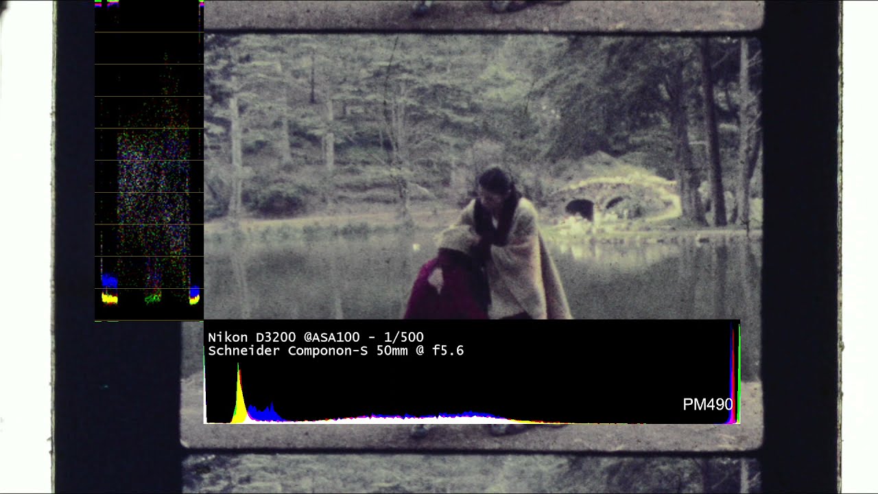
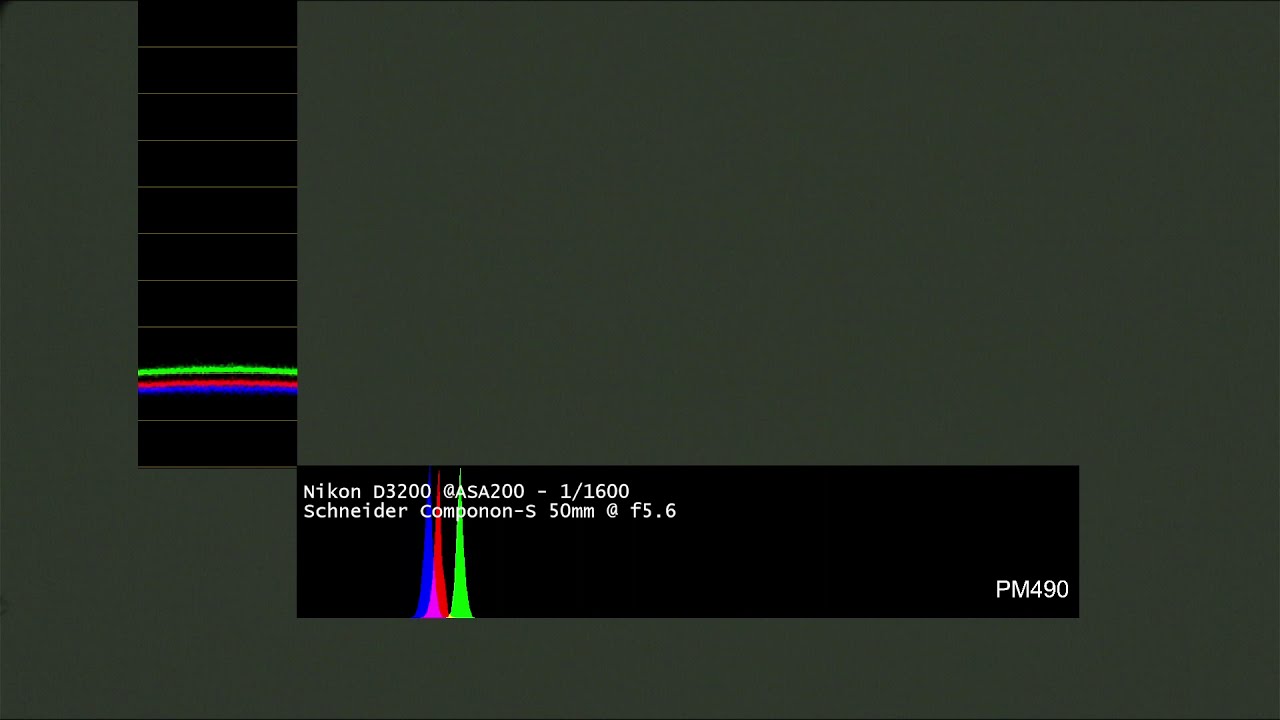
The human eye basically does not see flickering when the light is switched above a certain frequency. That is the principle of CRTs rendering an image. However the eye-shutter is much slower than what is available in cameras, so it is possible that while we see the light dimming, a camera with a faster shutter would see a portion of the frame lid, and a portion dark, or lines, or dots.
Controlling the light by rapidly switching on-and-off is possible, but it requires that the switching and the camera shutter are coordinated, making the LEDs and the diming dependent on the camera shutter settings.
Another alternative for an LED produce less light, is to lower its operating current. Making current constant, just less current, results in making less light.
Microcontroller control options
Basically it boils downs to Digital-to-Analog block. It can be an integrated DAC (serial or parallel), or a DIY DAC with an R-2R ladder. Another alternative is to convert a PWM into an analog voltage, basically an R-C circuit/low pass filter of the pulses becomes a DC corresponding to its proportion high/low.
PWM is common, and available in Arduino or Raspberry Pi. Some Arduinos provide 12-bit PWM and even the old Uno and Mega have work arounds for 16 bit outputs. Additionally, there are simple ICs/boards with multiple 16bit PWM, such as this one from Adafruit.
PWM solves the scalability issue, specially when some builds are looking to control R-G-B-W-Ir, and even multiple Rs or Bs.
Integrated Solutions
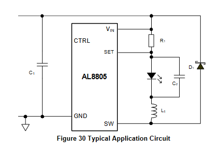
As mentioned in the Sasquatch 70mm scanner there are integrated solutions such as the AL8805 or its evaluation board made by Sparkfun, the femtobuck.
Why would one want to reinvent the wheel? It is fun… and because some of these may not be available where the film is at?
Control with PWM drive with constant current, scalable
Based on the above preamble, I created a driver configuration with transistors, to make a constant current-mirror driver controlled by a PWM.
Some advantages:
- Transistors are everywhere, chips are in shortage.
- Scalable both in the number of LEDs that can be controlled, and the colors-channels.
- Configurable to supplies of 12V, 24V or more. LEDs work in series but with typical drops around 3V, the number that can be in the same string is limited to the power supply voltage.
- Modular design. The configuration is simple enough that more LEDs can be added in series, or in parallel (the mirror transistor). Multiple channels can use the same design topology.
- In line with Kinograph philosophy: simple components, available worldwide.
Prototype
Using some particular LEDs (almost 1W each), I made a proof of concept and was very pleased with the results. It is a linear circuit, so ripple/noise on the power supply translates into visible noise. Because of it, I added a linear regulator on the PCB, can be used or not.
Documentation
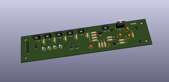
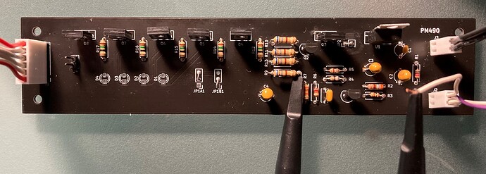
I’m behind on what I would like to do to simplify the work if anyone wishes to use the configuration, so at this time there are schematics with 12V and 24V examples, and PCB (through-hole). I ordered some components to assemble the PCB, and once completed, I will make some additional postings on how it works, and how to change values to adjust to your build. All documentation will be on github.com/PM490/framebyframe with progress postings on this trail.
Schematic Summary
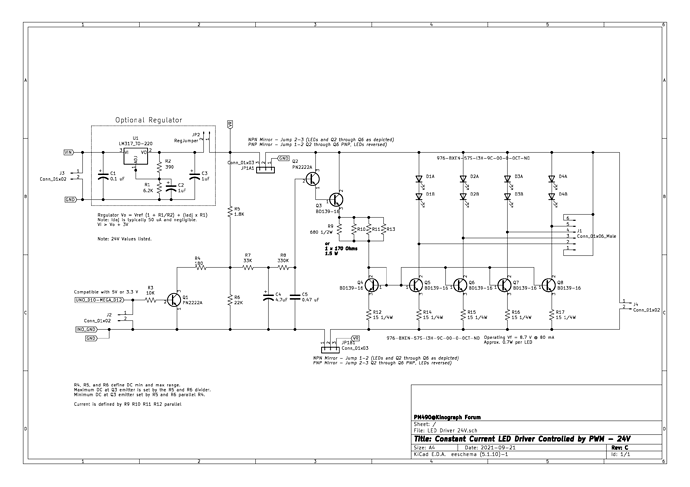
Here is a quick explanation of the blocks, to make the schematic simple to understand. Open it in PDF here
The building blocks are:
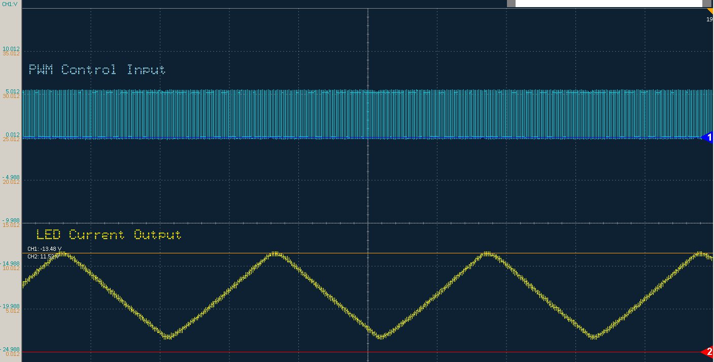
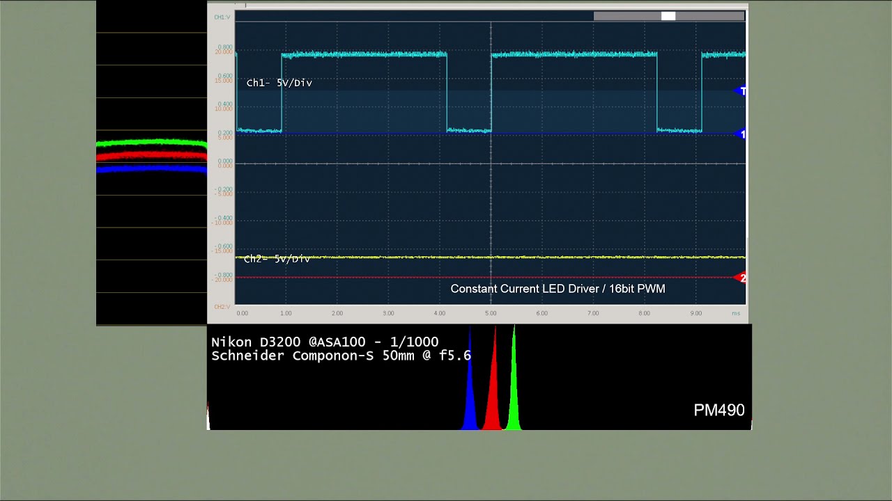
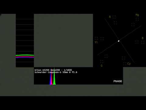
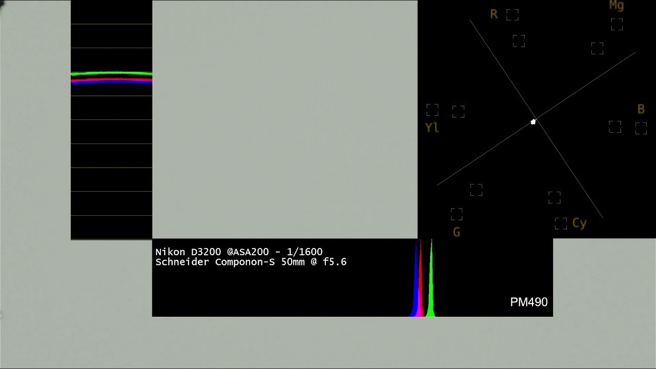
- Level shifting of the PWM - Q1 switches whatever PWM levels on J2 (light blue in the scope screenshot above), to the internal regulated voltage VR. Basically, if J2 receives 0-3.3V or 0-5V, Q2 makes it compatible with the regulated voltage VR by switching the voltage divider of R5-R6 or R5(R4 || R6).
- RC converts PWM to DC the output of the level shifting is low-passed with a couple of R-Cs, the time constant set is much higher than the typical PWM period, so the circuit is a bit slow to react for the benefit of a quiet DC output.
- Emitter follower - The DC output is passed through the Q2-Q3 emitter follower, which provides the isolation for the higher currency that is used to drive the current mirror Q4 (yellow in the scope screenshot above).
- Current Mirror - LED Drivers - R9 || R10 || R11 || R13 set the current on Q4, the current mirror configuration makes the current at the collectors of Q5, Q6, Q7, Q8 the same, as long as the mirror is within the compliance range. R9 || R10 || R11 || R13 may be replaced by a single high power resistor. Depending on the current required by LEDs and the voltage power supply, the resulting resistor will likely be higher than 1/2W.
In short, PWM is converted to DC with minimum and maximum values of DC chosen to keep the current mirror operating. The current is set by the parallel of R9 || R10 || R11 || R13.
@matthewepler is testing the circuit (actually 4 times the above, one for each led color RGBW). After I get components and assemble, will post additional pictures/information with measurements of the board.
Keep in mind
As with any project/part there are some trade offs.
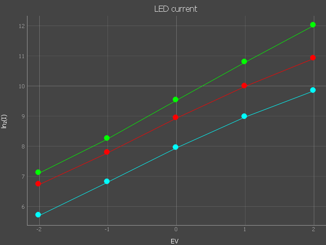
- The amount of light LEDs produce is not linear to current. Keep that in mind when writing the steps for the PWM. A look up table can make the range more useful depending on the application. That is one of the reasons why 8 bit PWM may not give enough resolution for fine-dim-control, consider using the alternatives for 12 or 16 bit PWM control described above.
- The PCB was made as through-hole. The mirror transistors were chosen considering that for the LEDs I selected are about 1W each. If LEDs require less or more current, Q3-thru-Q8 may be adjusted accordingly.
- The LEDs I use in this project have a Voltage Drop of 9V, that is about 3 times the typical LED. Depending on the particular LEDs and the power supply, one of the mirror-transistor may be able to drive multiple LEDs in series. In the 24V example depicted is only two (9V forward drop each).
- Four mirror outputs were chosen for the particulars of the LEDs on my project. In certain cases two or even just one may be sufficient, so only use Q6-Q7-Q8 as needed.
- The 16 bit timer is used by other arduino libraries (servo library for example) so it is wise to confirm that you have the processor timers available when doing the workaround to make the PWM 16 bit.
Sorry for the long post. Information provided as-is, use as you see fit. Hope this design is helpful to the community and assist you in getting your project moving and selecting the components to your built.
Again, PCBs and schematics are at github.com/pm490/framebyframe, more documentation to follow (when time permits).
Updated with language corrections, additional references, and illustrations
