Update
Half full cup, moving film without sprockets or sprocket detection with an uncertainty of 0.05 mm… Half empty cup, it may be as good as it gets.
It sure feels like everything everywhere all at once time.
- The sprocket detection algorithm works quite well.
- The 3D-printed guide rollers do a better job than the lego guides or the vinyl cutter rollers. All guides are the same 3D printed pictured previously.
- Unexpected project: began controlling the TMC2208 basic micro-stepping setup via UART.
- Found most of the significant contributors to the frame movement, spoiler alert it will be better, but there will still be some jumps.
Meanwhile, made some progress on a second round of PCB design.
Building upon the progress of the previous round:
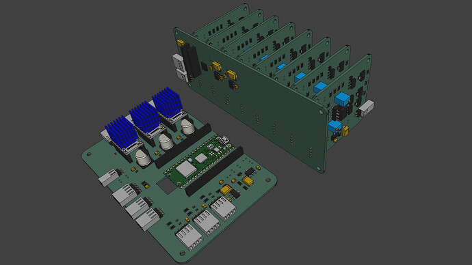
MCU - (132 x 86 mm) Pico, ADC conditioning for Tension, and three Analog Devices/Trinamic TMC2208 drivers, now configured via UART. Pictured in front. The MCU receives USB-serial commands from the controlling system (currently the Raspberry Pi) and handles movement (stepper control and tension sensing) and light (DAC control). Board was reformatted to be Pico-W friendly, opening the door for IP-WIFI communications in the future.
DAC - (150 x 60 mm) The eight channel 16bit DAC and its voltage conditioning are separate board, the backplane (pictured) serves to minimize wiring if more than one LED color is needed. It is controlled via I2C, which makes it universal enough to be controlled by boards other than the MCU. It is also possible for a single controller to drive additional instances of the board/DAC, and the board allows jumper configuration of the I2C address (2 bits, up to 4 DACs).
LED Linear Current Driver - Changed form factor to 60mm x 60mm, reducing the foot print of the DAC/Driver assembly. Each driver -up to eight per DAC- is controlled independently by one of the DAC channels. In this design, most components will be surface-mounted, the exception is due to price/availability. Each board is designed to control a separate type of LED, opening the door for narrow-band-multi-spectral scanning, or RGB, or WRGB, or WRB, or WRBG+IR or whatever is needed.
It has been 2 years since I posted the first linear current LED driver design, much has been learned, and much still to be learned on the subject.
This is a significant improvement over the typical LED drivers (femtobuck, etc), which can only control current for the top 80% of the range (20% to 100%). These linear current driver boards control the LED from 0 to 100% range (with the 16 bit resolution of the DAC). The trade-off is heat, and limits the current to about 400mA. Using 30Volts compensates for higher power, in the above pictured system, maximum output is about 8.5W with 12 White LEDs.
From what I see on linkedin, there are a couple of startups working on versions of multi-spectral film scanners… so here is a minimum viable light control system for 1 to 8 bands, and expandable to up to 4 DACs for a total 32 separate bands.
Each of these blocks may be used/improved/configured independently. For example, instead of the raspberry pi/HQ camera, a mac/pc/linux computer can equally control the MCU and use other camera systems.
Lookahead
- Finalize PCB design, order, and assemble.
- Incorporate stepper lessons into transport adjustments/improvements (and provide a report to the forum).
- Setup sprocket detection feedback to Pico, and continue scanning code development.
- Complete Pico usb-serial command set.
Everything is happening everywhere all at once!
Stay tuned.
