I’ve been enjoying the conversation about sprocket hole identification. @PM490 listed their motivation:
What is the motivation for others (@npiegdon@cpixip ) in identitying a sprocket? Alignment of successive frames? If so, what accuracy is required? Won’t a video stabilization step correct any jitter caused by errors in sprocket detection?
I mentioned my own motivation at the end of my September post. The short version is:
In extreme cases, the lack of frame-to-frame consistency made it harder for the stabilization plugin to do its job. (You can see some shaking around 0:09 in this video where it was too much.)
Knowing where the sprocket holes are gives an angle that can be used as a hint while calibrating the straightness of the film transport.
If you know the sprocket hole location and dimensions, you can infer the frame position and dimensions. This can be used as a safety check to make sure the entire frame is in the camera’s viewport before capturing an exposure. And while you’re at it, you can use the same dimensions to crop out any excessive over-scan (leaving, say, 5% instead of 20%) to save a little disk space and give the stabilizer (and other processes) fewer pixels to chew on.
For my part, the first one is the real reason. The other two are just nice things that you get for free once you complete the first one.
I really admire the work done on this sprocket holes detection, I admit that I wouldn’t be able to do it.
But my opinion is different:
A perfectly centered sprocket holes is not a guarantee of a stable image, because the cameras could also have adjustment faults. Sometimes we see a stable sprocket holes and moving image frames.
Anegdotally, I had imprecise sprocket holes on a film, they moved on the horizontal plane (probably a lack of perforation of the film).
On amateur films, the cameraman moved much more than the misalignment of the film
The projector still added some extraneous movements.
I also find that the video stabilization does a very honorable and very fast job which suits me.
Here is a small example (not perfect), of a very damaged film.
Thank you for your exchanges which I read with great pleasure.
with my scanner, I have experienced the same phenomene as Paplo @PM490 . Never was able to identify the root cause. Developed instead a fast enough sprocket registration algorithm and the issue was no longer relevant.
@justin would like to take this opportunity to thank you again for the stepper references. I hope to get to testing the different settings and hopefully make a determination of the factors/parameters which are creating the transport rhythm.
As @cpixip mentioned, he experience something similar.
For context it is worth to point out that there are no sprocket gears or optical detection of any kind, unlike other builds using mechanical or optical devices related to the sprocket hole position. So for Snailscan, the sprocket detection via the HQ camera is presently the only feedback for the controller that would provide the position of the sprocket hole.
@Roland, very nice examples of your work. One additional point in line with the above items is that the optical perception also served as stabilization, especially when a projector is used under normal settings (dark room with large screen).
For this project, I see the work on sprocket hole detection akin to an electronic claw. Basically, since presently the transport does not have anything that senses or moves the film based on a sprocket hole, the capture software will provide to the transport controller a feedback of the sprocket hole position.
The film I am using for testing reinforces your opinion. While the sprocket may be perfectly stabilized, the content of the image, and the image vertical borders are moving all over :). As much as I am liking the results of the sprocket algorithm, it will not aid to correct these.
Multiple Successive Approximation on All sides
In continuing testing, here are the results of another prototype round of the hole detection algorithm.
It uses an initial detection of the sprocket hole, with a first pass on the axis marked at the top of the window. The side marker indicates the location of the active area.
For the detection to kick in, the top of the sprocket must be below the top of the window, and above the left side marker. The video positions the hole slightly beneath to demonstrate when it kicks in.
The additional passes are performed using the rough center detected on the first pass to hone the location of all sides of the sprockets.
Each detection is marked with a dot. The alignment of the samples (dots on each side) are gauged against all others on the same side. A parameter allows to “drop” the outliers, which are depicted in red, making the side fairly resilient against local anomalies (see examples in the video).
The number of samples for each side can be as little or as much as it is desired. The nature of the successive approximations is discrete, and in the case of local anomalies, it is an interesting advantage. In the video some side dirt skews some location samples but is not detected by other samples.
Added some cropping lines to the full frame presentation, just to illustrate the results of the detection on the captured frame.
Not yet implemented, but the number of samples dropped may be used as a confident gauge to sidecar for post capture confirmation.
All the movement for this test was controlled by typing manually via Putty USB serial commands to the transport controller.
Thanks @Roland… I have to admit that I didn’t think I could do it either and it was a struck of luck to remember the old successive approximations. Math is not my strong suit, and also admire the work of @cpixip and @npiegdon which uses it exensively.
The sprocket hole, for most film gauges, is always the best way to register the film. For almost all professional 35mm formats, and for many 16mm formats, a registration pin in the camera was used to perfectly align the film to a known position that is consistent from frame to frame. Therefore using the sprocket holes to do the same in scanning is the right way to do it.
But you don’t need a registration pin for this to work. For example, my Eclair ACL 16mm camera doesn’t have a registration pin, but the images are remarkably steady due to the mechanical design, so the perforations are the best way to align frames.
There are exceptions to this - such as Super 8, where the perforations are inconsistent from frame to frame, from the time the perfs are punched at the manufacturer. Super 8 uses an edge guide for horizontal registration in the camera, so the perfs can be used for vertical registration (kind of, because technically the perf that’s in the pulldown claw at the time the image is taken is 2 frames away from the image itself). But the perfs are horizontally inconsistent relative to the edge of the film, so you need to use the edge of the film to stabilize.
All other standard gauges: 8mm, 16mm, 35mm, should use the perforations only because they don’t have this issue.
This is irrelevant to frame registration. The scanner’s job should be to make the FRAME as steady as possible. the image within that frame is something different. If you’re talking about steadying the image to correct for shakiness, that’s something you should do after the scan in software because it’s too easy for a stabilization algorithm that’s looking at the image itself to go off the rails, so you don’t want to be doing that while scanning. It needs to be done on a shot by shot basis, usually.
Again, this is irrelevant. Most projectors were not super steady. What does that matter? Steadiness can be obtained by using the perforations while scanning and overcoming the mechanical limitations of projectors…
There’s a reason all film scanners known for producing steady images do it this way (or in the past, used mechanical registration pins). Those that don’t (such as the Scanity, Spirit, Shadow, GoldenEye, and most other line-array or flying spot scanners) will have a lot of gate weave in their scans.
– that is interesting. Is this from your experience or is there any publication which goes into detail about this?
Looking at different projectors and S-8 cameras, it also seems that the registration uses only one of the horizontal edges of the sprocket for registration; the other one is never used.
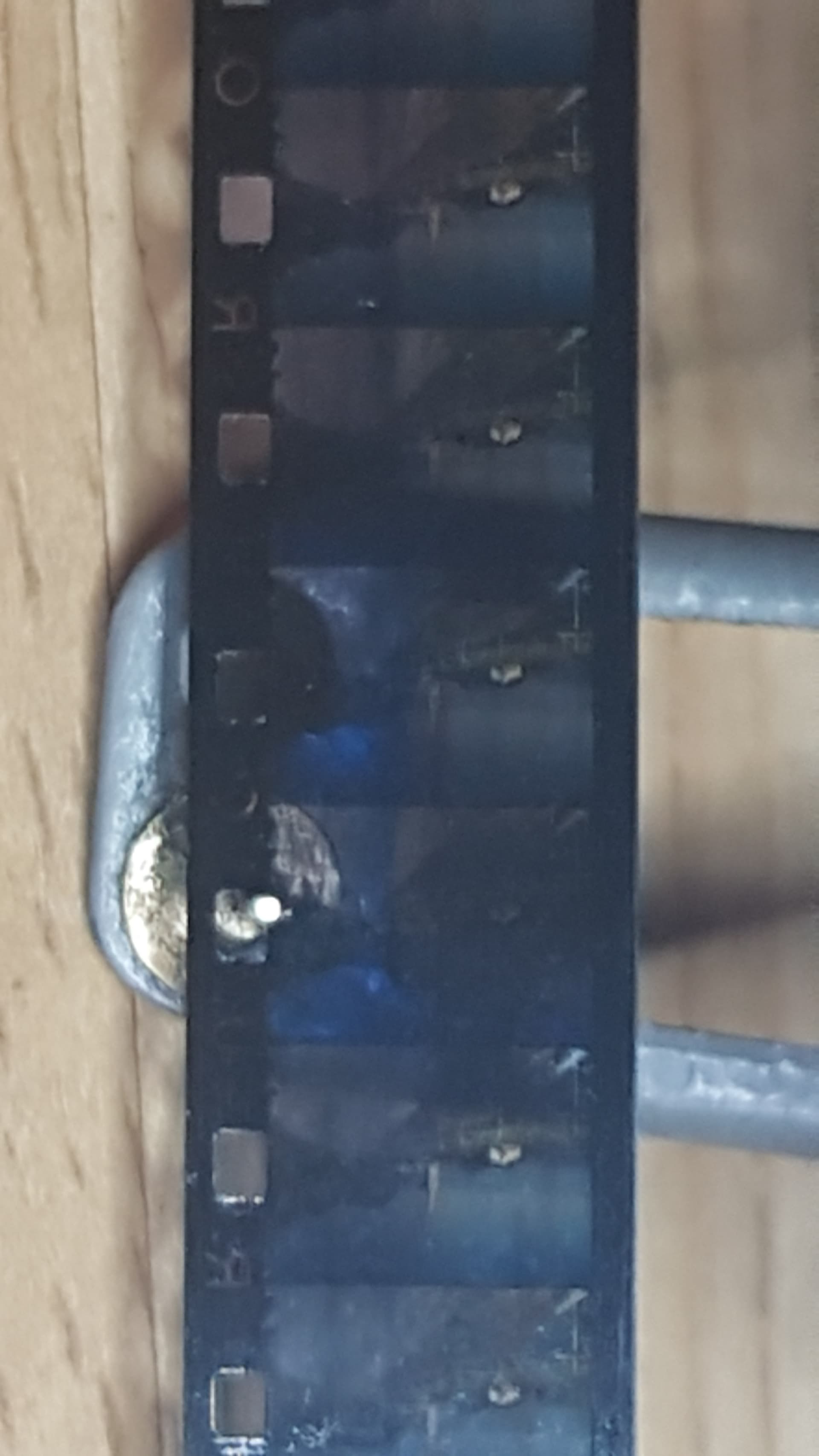
Note two things: the claw (right side) is only acting on one direction. And: there are two metal springs on the left side pushing the film toward the raised posts on the right side (where the sprockets are). Also, as @friolator remarked, one can clearly see the 2-frame separation between “registering claw” and optical window.
So horizontal alignment was done with the sprocket side of the film, while vertical registration was done only with (in this image) lower boundary of the sprocket hole placed 2 frames before the actual frame taken.
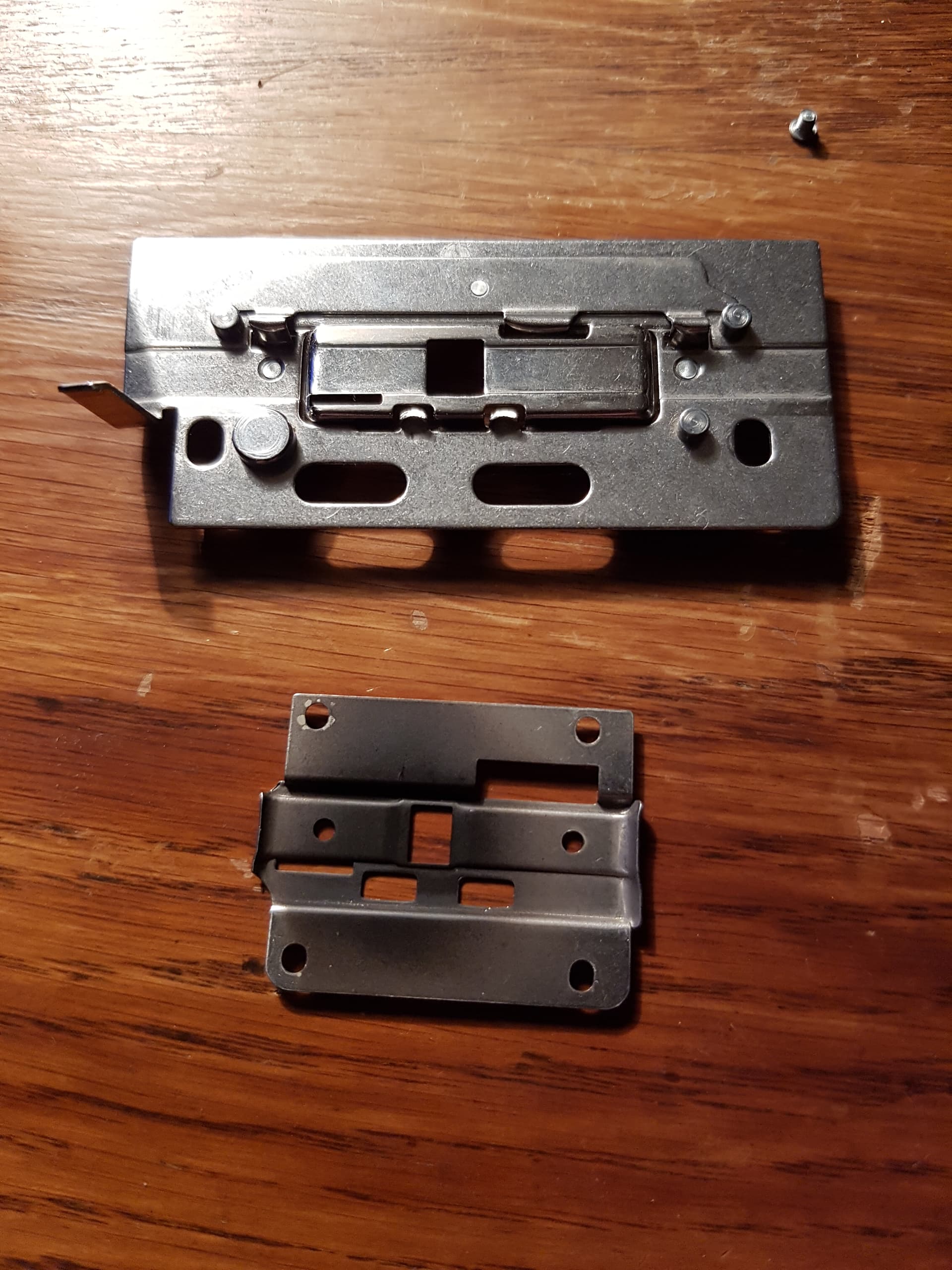
And here is an example of the claw a S-8 projector was using. Compare the size of the projector’s claw to the sprocket hole size of the S-8 film:
one basically notices the same “construction” with respect to the horizontal film alignment: metal springs (top of the upper gate part) pushing the film against fixed alignment posts on the sprocket side of the film.
Interestingly for me, the usual way of editing S-8 film was with transparent adhesive tape. It did wrap around the side of the sprocket hole, but did not cover the opposite side of the two to four film frames it covered, as can be seen by this image:
This leads to a shift during projection whenever there is a cut - as there is the additional tape enlarging/shifting the sprocket side of the film. As the width of S-8 seems to be rather constant (judging from a few measurements I have taken), I opted in my scanner to use the side opposite to the sprockets for horizontal alignment, which improved scanning results.
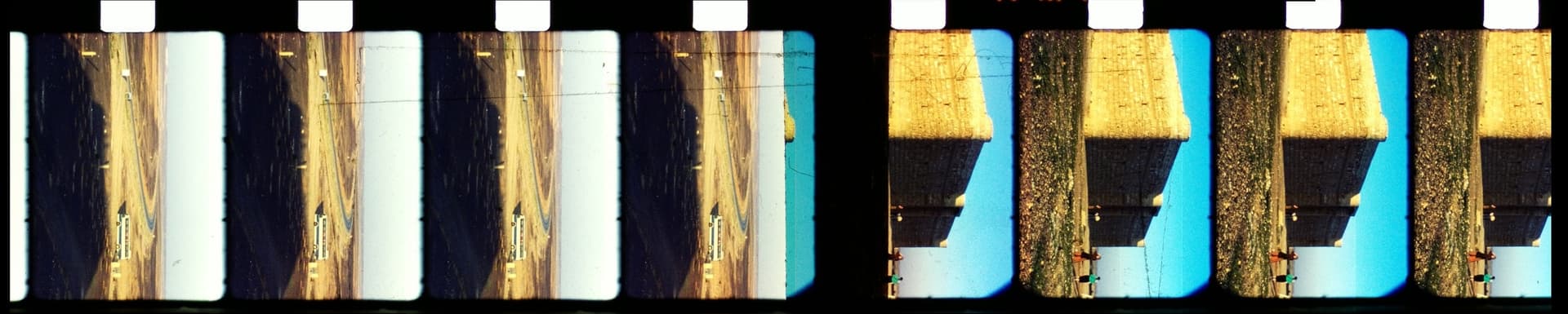
One last comment: at a time I was considering what I think is the ultimate sprocket registration: capture the frames with sufficient overlap to enable complete photogrametric reconstruction of the whole filmstrip. In this way, even multiple bad sprocket would not throw out the alignment process. In the end, I considered it not to be worth the trouble, but for you amusement, here are some examples of reconstructed film strips:
If you look closely, you can see a really large adhesive tape covering the edit visible in the center film strip. Here’s another film strip reconstruction, showing a failure of the film transport mechanism in camera:
Of course, with such a film strip approach, it would have been easy to incorporate the 2-frame separation between sprocket hole and film gate - this was the initial idea behind that approach.
This is a known issue. Kodak uses a 5-perf stamper to cut the perfs for Super 8. it is not perfectly parallel with the film, so it results in a sawtooth pattern, where one end of the stamper is closer to the edge than the other. The amount is miniscule, but it’s enough that if you use the perfs for horizontal registration, you will see that the picture will weave back and forth in a fixed pattern (5 frames). We worked closely with Lasergraphics and another company that uses their scanners to implement and test a software fix. Instead of using the perfs for S8 scanning, you use the film edge for horizontal registration (mirroring the edge guide in the camera), and the results are rock solid.
Super 8 was never a high quality format. It was about convenience, and many compromises were made in its design. The pulldown claw on better cameras is fatter, and acts like a registration pin. This moves the film slightly, so the steadiness is actually worse if you don’t emulate the edge guide, when you shoot with good cameras, than if you shoot with a cheap camera that has a small claw.
We have seen this problem in film shot in 1965, when Super 8 was a brand new format. It has always been there.
yep. That is what the old hardware also did use for horizontal frame registration (as I tried to elaborate upon in my previous post). And that is the horizontal frame registration my scanner is using.
Great insight. When time for Super 8 comes, in addition to the four sides of the sprocket hole detection, I will overscan the film side on the sprocket side and add a fifth detection for the film edge. Currently each side detected provides the image pixel coordinates, and all these can be preserved as a sidecard to the capture.
I can’t get into complicated debates, the subtleties of the English language escape me, as you will have noticed by trying to read me.
PM490
Even if the perforations are absolutely fixed, this won’t correct the other various sources of image or frame instability. If the perforations move a little (as little as possible, of course), it’s not a big deal, because after a little post-processing, it won’t be noticeable.
I work for clients who only judge the final result, not the copy that ends up in a museum.
I really like these rules:
Think 1 hour, work 5 minutes.
No problem can withstand a 16-hour work day.
A small example of the relative stability I achieve with my latest scanner.
Stepper motor drive, no tensioner, and laser perforation detection, scan speed 16i/s.
Update
I continue peeling the onion of the transport rhythm. While there has been progress, there is still some work to be done… so I will post the full breakdown when I finish breaking the onion, hopefully will help others planning to use steppers in similar transport.
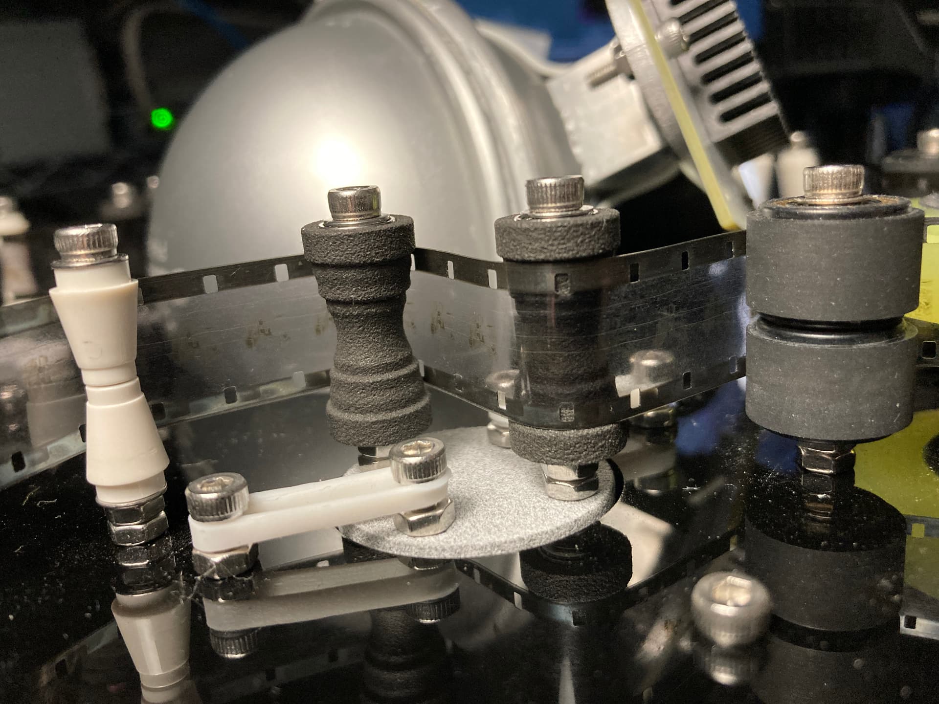
Meanwhile, I sent out to print a 16mm and 8mm guide roller. Love when life imitates CAD.
There are two bearings, top and bottom. It was first tested in the dancing pot hat, the tightest turn, and these worked well.
Waiting for more bearings to arrive in Amazon, and will test replacing the Lego guides (no bearing) and the vinyl cutter rollers (those have 2 bearings also) with new 3D printed.
The new rollers will minimize the film vertical shifting, especially for 16mm. And continue the goal of being able to scan 16, 8 and Super 8 without changing the path.
The material finishing is a bit coarse, these were printed in 3201PA-F Nylon.
Update
Half full cup, moving film without sprockets or sprocket detection with an uncertainty of 0.05 mm… Half empty cup, it may be as good as it gets.
It sure feels like everything everywhere all at once time.
The sprocket detection algorithm works quite well.
The 3D-printed guide rollers do a better job than the lego guides or the vinyl cutter rollers. All guides are the same 3D printed pictured previously.
Unexpected project: began controlling the TMC2208 basic micro-stepping setup via UART.
Found most of the significant contributors to the frame movement, spoiler alert it will be better, but there will still be some jumps.
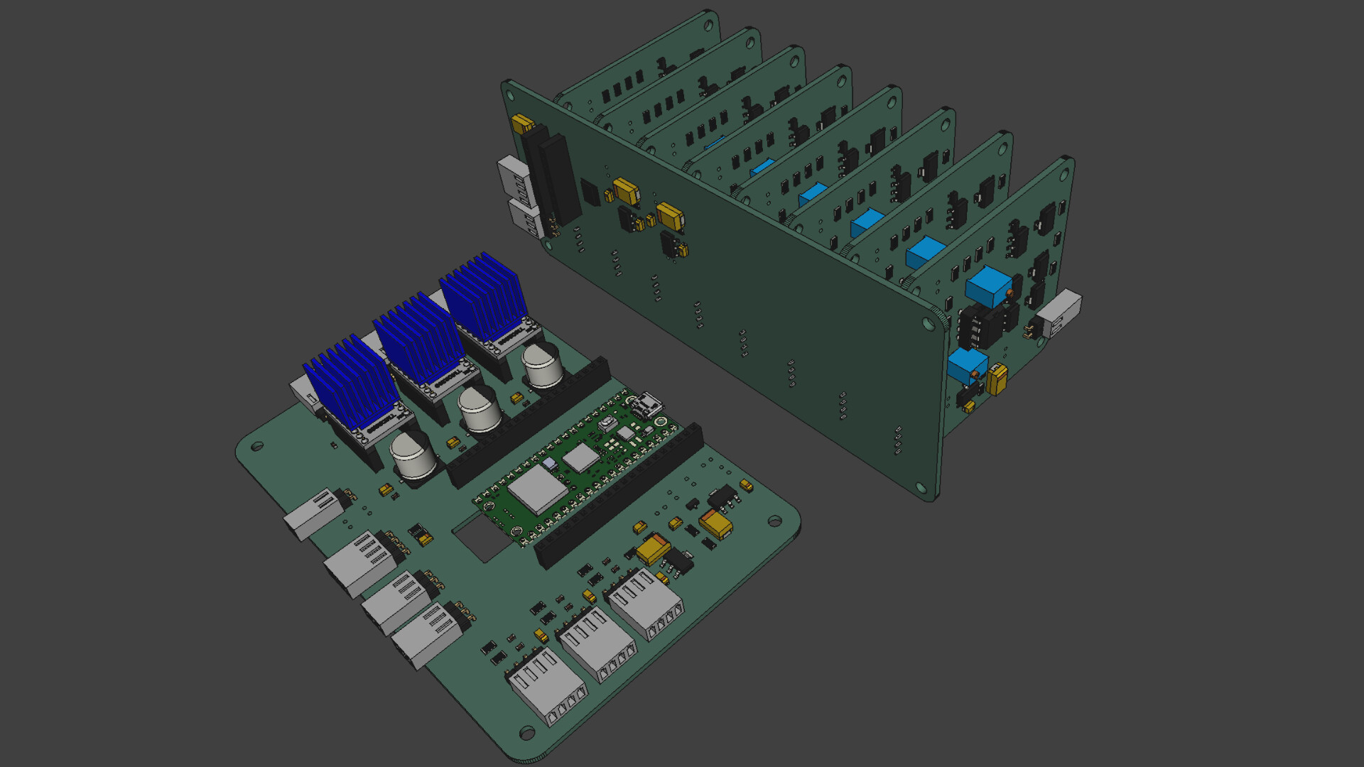
Meanwhile, made some progress on a second round of PCB design.
MCU - (132 x 86 mm) Pico, ADC conditioning for Tension, and three Analog Devices/Trinamic TMC2208 drivers, now configured via UART. Pictured in front. The MCU receives USB-serial commands from the controlling system (currently the Raspberry Pi) and handles movement (stepper control and tension sensing) and light (DAC control). Board was reformatted to be Pico-W friendly, opening the door for IP-WIFI communications in the future.
DAC - (150 x 60 mm) The eight channel 16bit DAC and its voltage conditioning are separate board, the backplane (pictured) serves to minimize wiring if more than one LED color is needed. It is controlled via I2C, which makes it universal enough to be controlled by boards other than the MCU. It is also possible for a single controller to drive additional instances of the board/DAC, and the board allows jumper configuration of the I2C address (2 bits, up to 4 DACs).
LED Linear Current Driver - Changed form factor to 60mm x 60mm, reducing the foot print of the DAC/Driver assembly. Each driver -up to eight per DAC- is controlled independently by one of the DAC channels. In this design, most components will be surface-mounted, the exception is due to price/availability. Each board is designed to control a separate type of LED, opening the door for narrow-band-multi-spectral scanning, or RGB, or WRGB, or WRB, or WRBG+IR or whatever is needed.
This is a significant improvement over the typical LED drivers (femtobuck, etc), which can only control current for the top 80% of the range (20% to 100%). These linear current driver boards control the LED from 0 to 100% range (with the 16 bit resolution of the DAC). The trade-off is heat, and limits the current to about 400mA. Using 30Volts compensates for higher power, in the above pictured system, maximum output is about 8.5W with 12 White LEDs.
From what I see on linkedin, there are a couple of startups working on versions of multi-spectral film scanners… so here is a minimum viable light control system for 1 to 8 bands, and expandable to up to 4 DACs for a total 32 separate bands.
Each of these blocks may be used/improved/configured independently. For example, instead of the raspberry pi/HQ camera, a mac/pc/linux computer can equally control the MCU and use other camera systems.
Lookahead
Finalize PCB design, order, and assemble.
Incorporate stepper lessons into transport adjustments/improvements (and provide a report to the forum).
Setup sprocket detection feedback to Pico, and continue scanning code development.
Complete Pico usb-serial command set.
Everything is happening everywhere all at once!
Stay tuned.
@PM490 - what code are you using on the Pico to drive the TMC2208? I am currently driving the film movement stepper with an Arduino Nano, utilizing constant acceleration and de-acceleration. For this to work, TIMER1 (16 bit) is required for appropriate precision.
Specifically, my stepper need to do 400 microsteps exactly to advance one frame - however, the Arduino gets sprocket registration data from the RP4 (via USB-serial) to center the next frame slightly better. So the actual steps taken vary from about 390 to 410. I am using constant acceleration (that is, a linear velocity ramp at the start and end of the movement) to reduce wear on the film stock and to reduce the overall time a single frame advance takes. Specifically, about 100 steps is the initial acceleration part, about 200 steps are performed at maximal velocity, and the final 100 steps are used to ramp down the velocity to a stop. In this way, the maximal velocity you can achieve without the stepper loosing steps is a little bit larger.
At least with bare Micropython on the Pico, I could not reach the precision needed for that scheme. Standard timers in Micropython have a minimum time interval of 1 ms, and I would need at least an order of magnitude better. Of course, you could program the Pico in C/C++, could use one of the PIOs, etc… So I am curious about your software approach…
Simple answer: Bit banging C++ in the Pico.
Started handling the configuration of the TMC with the UART, which provides access to more/less microsteps (1 to 256 per step).
In my case, the capstan moves at a constant number of steps, but the direct driven pickup and supply reels steps are dependent of the spool diameter.
While using a timer certainly makes it more precise, given the requirement to move all three at different rates and at simultaneously made the timer alternative a bit too complex.
Your setup is very similar. I do not plan to have sprocket detector hardware, the detection feedback will also be from the RP4 via USB-serial.
It hasn’t been difficult to work with the toolchain in Pico, but if you are already familiar with arduino, that is also another alternative… arduino IDE with the Pico. I would certainly recommend using the Pico toolchain, the SDK is well documented and other than a bug with USB-Serial, I did not have any issues.
Also using constant acceleration for the capstan, and dividing the steps in 4 blocks.
Very looong answer: Interlacing the Steppers
In the three stepper implementation, pickup/supply movements are interlaced based on tension and direction of movement, and the result is that these do not move with constant acceleration.
The implementation senses tension, considers what the film is doing (moving forward/backwards or still) and determines what pickup and supply need to do (simultaneously with the capstan movement) for tension.
The options are: Move Clockwise (CW), Move Counter Clockwise (CCW) or not move = a delay equivalent to the step (DLY).
Supply
Action
tens_ok
cpst_still
cpst_rev
tens_h
Case
Direction
0
0
0
0
0
Moving Forward, Tension Low
DLY
0
0
0
1
1
Moving Forward, Tension High
CW
0
0
1
0
2
Moving Reverse, Tension Low
CCW
0
0
1
1
3
Moving Reverse, Tension High
DLY
0
1
0
0
4
Not Moving, Tension Low
CCW
0
1
0
1
5
Not Moving, Tension High
CW
0
1
1
0
6
Not Moving, Tension Low
CCW
0
1
1
1
7
Not Moving, Tension High
CW
1
X
X
X
Default
Tension Ok
DLY
Pickup
Action
tens_ok
cpst_still
cpst_rev
tens_h
Case
Direction
0
0
0
0
0
Moving Forward, Tension Low
CW
0
0
0
1
1
Moving Forward, Tension High
DLY
0
0
1
0
2
Moving Reverse, Tension Low
DLY
0
0
1
1
3
Moving Reverse, Tension High
CCW
0
1
0
0
4
Not Moving, Tension Low
CW
0
1
0
1
5
Not Moving, Tension High
CCW
0
1
1
0
6
Not Moving, Tension Low
CW
0
1
1
1
7
Not Moving, Tension High
CCW
1
X
X
X
Default
Tension Ok
DLY
The above are implemented in a switch-case. The need for this is due to the uncertainties of the tension sensor, one should avoid the pickup/supply moving contrary to the film movement.
For example, in case 0 of supply if tension is low, to increase the tension, the supply holds position because the film is moving forward, which would increase the tension. If that is not considered, and only tension is looked at, one may think the best alternative is to move the supply CCW, which would increase the tension… but that would actually create jitter/oscillation.
The beauty is keeping the time of the process the same, regardless of what supply/stepper need to do… reason why when these do not move, there is a filler delay.
Also note that the same function can be called just to setup/adjust tension (when cpst_still = true).
Capstan to Supply (or Pickup) ratio
In the context of variable spool ratio, and potentially different stepper gear-ratio and/or micro-stepping between the capstan and the supply or pickup, it was necessary to insure that the ratio of cycles pickup/supply to capstan would be adequate so all three would have sufficient loop-cycles to make the corresponding steps. And follow changes on the micro-stepping configuration.
This is akin to a firmware gear setup. Determining what would be the maximum ratio between the reel and the capstan, determines the gear ratio of the loop… but based on the above tension case, it only provides the opportunity for the reels to move, tension has the final word.
Constant Acceleration times the Capstan to Reel ratio
As a result of the interlacing, the capstan coefficients calculated for constant acceleration are in fact multiplied by the loops of the capstan to supply maximum ratio.
For example. if the diameter of the capstan is 50mm, and the maximum diameter of the supply/pickup is 200mm, and minimum of 32mm, with an equal micro-stepping setting of 3200 micro-steps/turn, the ratio of capstan to reel would be from 0.64 to 4. The firmware gear provides the opportunity to the reels to move more than 4 times the number of steps that the capstan will move.
Summary
The short story is that for every movement the capstan is moving using the constant acceleration coefficients, times the Capstan to Reel factor. The factor does not change through the movement, so the result is constant acceleration for the capstan.
The reels move with the same coefficient for the x cycles of the reel ratio. In the example above, reels go 4 cycles with C0, then 4 cycles with C1, then 4 cycles with C2, etc. But they will move only if the tension case determines. Every 4th cycle, the capstan always moves, which makes the capstan move with a period of 4xC0, then 4xC1, then 4xC2.
The rough code in progress
void ss_Move::MovingAcc (uint CapstanSteps, bool CapstanStill, bool CapstanRev, bool verb ) {
   uint8_t sp_dir_step = 0;
   bool loop_tension = true;
   int capstan_ctr = 0;
   int capstan_gear = 0;
   int tension_ratio_ctr = 0;
   int capstan_ratio = ss_capstan_ratios [Move_Capstan->ss_tmc_ms21_set*4+Move_Pickup->ss_tmc_ms21_set];

   // Acceleration Variables
   int32_t acc_steps = 0;
   double usec_x_cn = 0.0;
   double stepper_alpha = 0.0;
   double c0 = 0;
   double c1 = 0;
   double cl = 0;
   double cn = 0;

   acc_steps = CapstanSteps / 4;

   if (acc_steps > 300) {
       acc_steps = 300; // Cap at 300 if larger
   }
   stepper_alpha = 2.0 * M_PI / (double) (Move_Capstan-> ss_tmc_ms21_steps[Move_Capstan->ss_tmc_ms21_set] * Move_Capstan->ss_tmc_gear_ratio);
   c0 = Move_Capstan->ss_tmc_inv_tt * sqrt( (double) 2.0 * stepper_alpha / Move_Capstan->ss_tmc_max_acc [Move_Capstan->ss_tmc_ms21_set]);
   c1 = c0 * (double) 0.676;

   // Get the Driver out of automatic standstill current reduction
   Move_Capstan->StepperDisable (); //Disable with Direction
   Move_Supply->StepperDisable (); //Disable with Direction
   Move_Pickup->StepperDisable (); //Disable with Direction
   Move_Supply->StepperEnable (!CapstanRev); //Enable with Direction
   Move_Pickup->StepperEnable (!CapstanRev); //Enable with Direction
   Move_Capstan->StepperEnable (!CapstanRev); //Enable with Direction

   // Tension Loop
   while (loop_tension){
       // Move capstan gear, capstan if not still
       capstan_gear += 1;
       if (!CapstanStill && (capstan_gear == capstan_ratio)) {
           if(!CapstanStill && capstan_ctr < CapstanSteps){
               Move_Capstan->StepperFastStep(0);

               // Ramp Up
               if (capstan_ctr < acc_steps) {
                   switch (int(capstan_ctr))
                       {
                       case 0:
                           cn = c0;
                           break;
                       case 1:
                           cn = c1;
                           break;
                       default:
                           cn = cl - (2*cl / ( 4 * capstan_ctr + 1));
                       }
                       cl = cn;
                       usec_x_cn = cn * (double) 1000000.0 / Move_Capstan->ss_tmc_inv_tt;
                   }

               // For the period between acc_steps and 3*acc_steps it would use the last usex_x_cn as the delay.

               // Ramp Down
               if (capstan_ctr > (CapstanSteps - acc_steps)) {
                   switch (int( CapstanSteps - capstan_ctr))
                       {
                       case 0:
                           cn = c0;
                           break;
                       case 1:
                           cn = c1;
                           break;
                       default:
                           cn = cl / (1 - (2 / (4*( (double) (CapstanSteps - capstan_ctr) + 1) + 1)));
                       }
                   cl = cn;
                   usec_x_cn = cn * (double) 1000000.0 / Move_Capstan->ss_tmc_inv_tt;
                   }
               capstan_ctr += 1;
           }
           else{
               busy_wait_us_32(10);
           }
           capstan_gear = 0;
       }
       else {
           busy_wait_us_32(10);
       }

       sp_dir_step =  ss_Move::TensionStepperAction (CapstanStill, CapstanRev);

       switch (sp_dir_step) {
           case 0 :
               // No Movement
               busy_wait_us_32(Move_Supply->ss_tmc_step_set); // Delay For Non-Moving Stepper
               busy_wait_us_32(Move_Pickup->ss_tmc_step_set); // Delay For Non-Moving Stepper
               break;
           case 1 :
               // Pickup Only - CCW
               Move_Pickup->StepperEnableWait (0); //Enable with Direction CCW
               Move_Pickup->StepperFastStep(0);
               busy_wait_us_32(10); // Delay For Non-Moving Stepper
               break;
           case 3 :
               // Pickup Only - CW
               Move_Pickup->StepperEnableWait (1); //Enable with Direction CW
               Move_Pickup->StepperFastStep(0);
               busy_wait_us_32(10); // Delay For Non-Moving Stepper
               break;
           case 4 :
               // Supply Only - CCW
               Move_Supply->StepperEnableWait (0); //Enable with Direction CCW
               Move_Supply->StepperFastStep(0);
               busy_wait_us_32(10); // Delay For Non-Moving Stepper
               break;
           case 5 :
               // Pickup CCW - Supply CCW - 5
               Move_Supply->StepperEnableWait (0); //Enable with Direction CCW
               Move_Pickup->StepperEnableWait (0); //Enable with Direction CCW
               Move_Supply->StepperFastStep(10);
               Move_Pickup->StepperFastStep(10);
               break;
           case 7 :
               // Pickup CW - Supply CCW - 7
               Move_Supply->StepperEnableWait (0); //Enable with Direction CCW
               Move_Pickup->StepperEnableWait (1); //Enable with Direction CW
               Move_Supply->StepperFastStep(10);
               Move_Pickup->StepperFastStep(10);
               break;
           case 12 :
               // Supply Only - CW
               Move_Supply->StepperEnableWait (1); //Enable with Direction CW
               Move_Supply->StepperFastStep(0);
               busy_wait_us_32(Move_Pickup->ss_tmc_step_set); // Delay For Non-Moving Stepper
               break;
           case 13 :
               // Pickup CCW - Supply CW - 13
               Move_Supply->StepperEnableWait (1); //Enable with Direction CW
               Move_Pickup->StepperEnableWait (0); //Enable with Direction CCW
               Move_Supply->StepperFastStep(10);
               Move_Pickup->StepperFastStep(10);
               break;
           case 15 :
               // Pickup CW - Supply CW - 15
               Move_Supply->StepperEnableWait (1); //Enable with Direction CW
               Move_Pickup->StepperEnableWait (1); //Enable with Direction CW
               Move_Supply->StepperFastStep(10);
               Move_Pickup->StepperFastStep(10);
               break;
           }

       if(usec_x_cn == 0.0 ){
           busy_wait_us_32(uint32_t (c0 * (double) 1000000.0 / Move_Capstan->ss_tmc_inv_tt));
       }
       else {
           busy_wait_us_32(uint32_t (usec_x_cn));
//            printf("capstan_ctr = %03d us_x_cn = %f \n", capstan_ctr, usec_x_cn);
       }

       // Check for reaching Capstan ratio
       tension_ratio_ctr += 1;
       if (CapstanStill) {
           if (tension_ratio_ctr == capstan_ratio*4){
               loop_tension = false;
           }
       }
       else {
           if (tension_ratio_ctr == CapstanSteps * (capstan_ratio)){
               loop_tension = false;
           }
       }
   }

   if (verb) {
       printf("|cmd:");
   };

}
The code is a bit rough, hope it helps understand how is presently implemented.
Interesting approach! My own implementation is using self-made tension sensors (basically a movable arm connected to a standard potentiometer, here are some old images of this construction) on the pickup and supply tables + a movement stepper driving a sprocket gear stolen from an old S-8 projector.
Film advance is triggered by a serial movement command specifying the amount of movement needed to advance to the next frame. This comes from the RP4 which has detected the sprocket hole position in the current frame.
Once that movement is triggered, the Arduino starts accelerating the movement stepper in order to advance the frame (TIMER1 interrupt driven). Due to this movement, the tension on pickup-spool is reduced and correspondingly, the tension on the supply spool is increased. This is of course noticed by the tension sensors - their reading is input into two PID controllers which drive the steppers for the pickup and supply plates. The two PIDs run in an interrupt loop of TIMER2 which drive the pickup and supply steppers as well.
In my setup, it is rather easy to change (independently) the tensions on the pickup and supply side - the RP4 can command a different zero position of the tension sensors. In fact, the supply plate works with less tension than the pickup plate. This is needed because the sprocket gear’s pins are smaller than the sprocket hole of the film. So I need to make sure that the sprocket pins always align on the correct side of the sprocket
While there is no need to monitor the spool ratio in my approach, the tension steppers only react to the movement of the film stepper. So you always introduce a little delay/jitter in the actual tension. Your idea of interlacing can in principle deliver a much smoother ride in term of tension variation - which might be important in order to minimize the risk of slipping on the capstan.
Thanks for sharing the insights into your Pico-programming. I was actually hoping to avoid C/C++ programming when using the Pico ( ), but it seems not to be possible when tight timing is required. I think I stick for the time being with my Arduino - it works ok with the small standard spools of 15m film length (3 min/3") up to 240 m length (40 min/10") ones. But the tuning of the PID parameters of the controllers was quite a challenge…
From what I am learning on researching the uncertainty on my transport (sprocketless), I would speculate that the above is a contributing factor to the source of your movement uncertainty. Another likely contributor is the independence of the pickup tension. My hypothesis would be that the combination provides an opportunity for the film to separate from the pin. I say contributors, because there may be backslash on the driving belt also.
Well, my system I described above just works fine. No issues in scanning S-8 film rolls with over 40 minutes running time. I was just considering to replace my Arduino Nano programmed in C/C++ with a more modern approach based on Micropython and the Pico. I think I programmed in C for more than 20 years now, somewhat less in C++, and I kind of got bored with these languages. But, it seems the time is not yet ripe for using Micropython on a Pico for such tasks…
I have not used micropython, but was curious about the limitation.
According to this February 2023 post:
The current version of MicroPython for the Pi Pico does not allow the hardware timers to be used separately . Instead, it is possible to create an almost unlimited number of “software” timers, all of which rely on a single hardware timer.
That appears to be the case currently… for the PICO. In the latest development branch for the WyPi, there are documentation references to hardware timers with a 1 microsec timebase.
You may have to wait a bit for the PICO… but there are ripping signs. At least micropython seems to be taking steps with other hardware to implement hardware timers with microsecond timebase.
Not sure of the particulars of your requirement, but there maybe a workaround using DMA to an output, and hardware it as an input to trigger an input interrupt. DMA allows for changing the output with every cycle (125 MHz) so that is plenty fast (maybe too fast).