Having a hard time drinking from the Python Qt5 hydrant to make a decent GUI.
In the meantime, sharing a bit more detail.
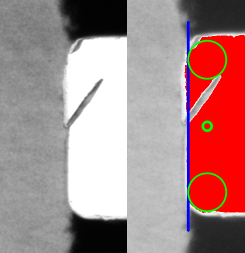
Successive Approximations
This method is widely used for ADCs in the form of a DAC providing a comparison value, against a level that one wishes to measure.
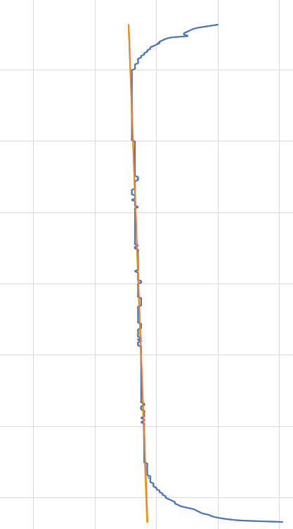
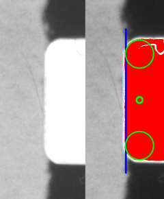
If one takes a slice of the film within the area of the sprocket, the idea is Y becomes the level (analogy would be the DAC), and the pixel content (black or white) becomes the result of the comparison (if the DAC is higher or lower than the level, in this case the edge). For this to work, without additional processing, the requirement is that the edge of the film above/below the sprocket hole is darker than the value of the hole.
   #Detection Area
    im3 = im0[:1023,:511] # y:yw, x:xw

    #Detection Parameters
    edge_level = 127 #Threshold
    sampling_axis = 255

    #Detect Top Edge of Hole
    tedge = 0
    for yt in range (8,-1, -1):
        if (im3[tedge+(2**yt)][sampling_axis][2] < edge_level and
            im3[tedge+(2**yt)][sampling_axis][1] < edge_level and
            im3[tedge+(2**yt)][sampling_axis][0] < edge_level):
            tedge = tedge + 2**yt

    #Detect Bottom Edge of Hole
    bedge = 0
    for yt in range (8,-1, -1):
        if (im3[bedge+(2**yt)+tedge][sampling_axis][2] > edge_level and
            im3[bedge+(2**yt)+tedge][sampling_axis][1] > edge_level and
            im3[bedge+(2**yt)+tedge][sampling_axis][0] > edge_level):
            bedge = bedge + 2**yt
    bedge = bedge + tedge

    sprocket_heigth = bedge-tedge

    #Detect Left Side of Hole
    xedge = 0
    for xt in range (7,-1,-1):
        if (im3[tedge+int(sprocket_heigth/2)][xedge+2**xt][2] < edge_level and
            im3[tedge+int(sprocket_heigth/2)][xedge+2**xt][1] < edge_level and
            im3[tedge+int(sprocket_heigth/2)][xedge+2**xt][0] < edge_level):
            xedge = xedge + 2**xt
In the above code, all 3 channels (RGB) would have to be above the edge_level value.
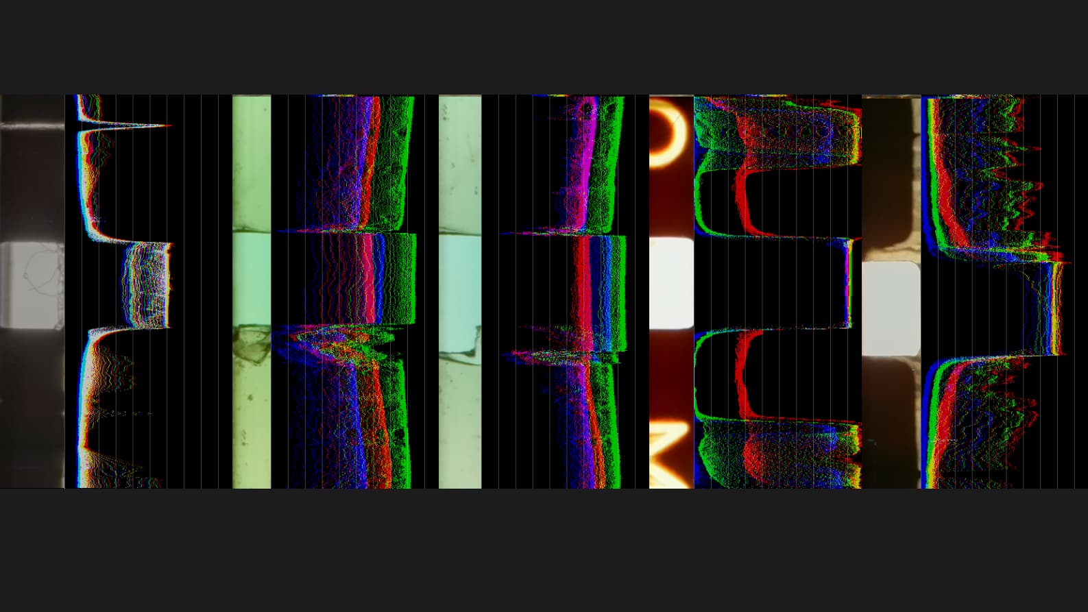
Simple Waveform
For testing, I also coded a simple python/opencv waveform, trying to keep processing reasonable. The code is quite simple.
    #capture from Camera
    im0=piCam.capture_array()

    #create 1/8 size for presentation
    im1 = cv2.resize(im0,(0,0),fx=0.125, fy=0.125) #resize to 1/8 (380,504)
    # 3040,4056 - 1520,2028 - 760,1014 - 380,507
    wvfim = cv2.cvtColor(cv2.resize(im1,(0,0),fx=1, fy=0.025), cv2.COLOR_BGR2GRAY) #resize to 1/8 (380,504)

    wvfm = np.zeros((256,504), dtype="uint8")
    # markers
    for gy in range (0,255,26):
        wvfm = cv2.line(wvfm, (0,gy), (503,gy),64,1)

    # waveform
    for gx in range (0,503,1):
        for gy in range (0,9,1):
            wvfm[255-wvfim[gy][gx]][gx] = 192
im0 is the full resolution.
im1 is 1/8 of resolution, image captured presented.
wvfim is compressed vertically to minimize the number vertical samples to 10.
Here is how the above looks on a Raspberry Pi4, all presented with opencv windows.
Commands are typed on Putty to the Pico controller, which handles light and transport (steppers and tension).