July/August: Direct Drive Transport (part 1)
Last time, the wires for the transport steppers weren’t even connected. Now, the ReelSlow8 can reliably maintain tension while moving.
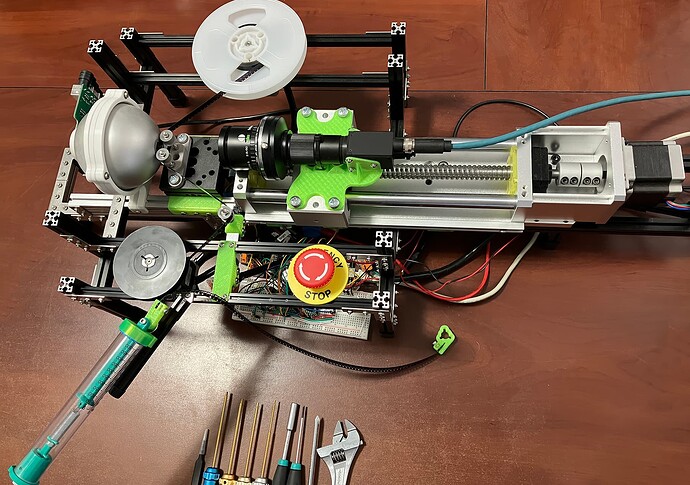
The picture hasn’t changed much; just fewer loose wires, the classroom scale is still there from calibration, and the E-stop finally found a home where it’s easier to press.
That said, there are some really cool details where things have started to come together in a way that feels like more than the sum of their parts.
Load Cell Linearity
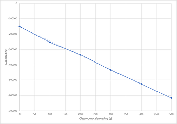
I wanted to get an idea about what sort of curve I was going to need to model in the software to convert raw ADC counts from the load cell into a tension measurement. So, I mounted the classroom scale close to the same position and angle the incoming film would normally be coming from. Connecting the other end of the little snippet of film to the take-up hub, I can pull the scale out to some number and lock it in place with a screw.
Testing at each 100g on the scale, averaging a few hundred readings at each point, these were the results:
That the linear trend-line is almost hidden by the data itself across the entire range is about as good as you could hope for. So, now that I know the slope for this particular load cell, all the app needs to do is “tare” using a single 0g data point. Nice and easy.
Key takeaway: treating the load cell data as perfectly linear seems like a safe assumption.
Load Cell Creep
Something you notice when watching the ADC counts rolling in at ~90Hz is that those lower 10 or so bits (of 24) are always walking around all over the place. It’s not just white noise, it’s sort of shimmying around over time. I’d also noticed that just after making a large tension adjustment with the classroom scale (say, more than 100g from where it was before) that over the next couple minutes, the random walking behavior in the data seemed to trend more in one direction than the other.
To try and characterize this creeping behavior, I performed the following experiment:
- Remove everything from the film path (0g tension) for >24h.
- Use the classroom scale to tension the load cell to 200g.
- Leave it at 200g for >24h.
- Remove everything (0g again).
Then, immediately before/after and 5min before/after each of those steps, I would take an ADC reading.
I was happy to find that the wiggly lower bits were less trouble than they appeared to be. I never saw any deviations larger than 1.7% (of the 200g), so maybe a 3.3g deviation in the worst case (reading immediately after a large change when the load cell has been in a different position for a long period). In most situations, the error was below 0.8%.
My own target when moving the film is to maintain a range of about 15g from my desired set point, so the worst case is already inside my noise allowance. To improve things, I could pre-tension the machine to my typical running set-point the night before I plan to use it.
Key takeaway: don’t plan on splitting grams, but our application never needed to in the first place.
Film Path Safety
So, these reels are precious family relics. I want it to be near-impossible for my buggy code to do any harm to this stuff. Beyond the E-stop button (which physically severs all motor current), I wanted something automatic in-place that could react faster than I can.
I wasn’t quite sure how to get the kind of guarantees I was looking for from a single Arduino. I’ve been avoiding interrupt-driven microcontroller code just for ease of reasoning, so reading from the load cell involves polling and busy waiting. For similar reasons, I’ve opted to “bit bang” the actual step pulses to the stepper controller boards rather than using something like PWM and crossing my fingers that I get the timing/counting right.
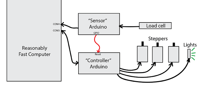
So a natural architecture fell out of my (made-up) requirements that ended up working well for the safety I was looking for:
The “controller” Arduino sits and waits for messages, responding to each one in turn. The “sensor” microcontroller just has the fire hose of load cell readings dumping into its serial output. By adding a single command to the sensor board, I was able to get exactly what I wanted.
One of the first operations you perform when launching the desktop app is to tare the load cell by averaging a hundred or so readings when nothing is touching it. Once the app knows the appropriate zero-point (and constant intercept), it sends the sensor board a min/max limit. From that point on, if it ever sees a reading above or below that range, it immediately pulls the reset pin on the other board. The initialization routine on the controller board sets the motors to 0% current, so the tension is dropped to zero.
My favorite part of this scheme is the low-latency. No USB round-trips, no queued serial messages, and no I/O delays inside the OS. Microseconds after the load cell knows about the problem, it’s stopped.
I’ve already accidentally tripped that safety mechanism a half-dozen times and it’s worked flawlessly every time. It’ll trip just from tugging on the film with your finger.
The controller board also sends a startup message when it is reset, so the desktop app can interrupt its current operation (if any) and show a big, red warning message that requires user intervention before continuing.
Since I got that up and running, my worries about accidentally destroying these family memories have been allayed.
Key takeaway: it’s better to put the time in on this kind of stuff up front before an accident happens, if only for peace of mind.
Simple(r?) Super-8 Sprocket Detection
I’d been planning to use a scheme like @cpixip’s Simple Super-8 Sprocket Registration as most of the criteria there (sub-pixel registration done in a separate pass, etc.) applies to this machine as well.
My app doesn’t stop on frame boundaries yet, but I had a shower thought the other day about a method that requires many fewer calculations and steps to get a rough sprocket hole position and decided to try it.
It relies on the assumption that the film will be properly exposed so that sprocket holes are the only “burned out” areas in the image.
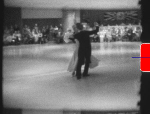
The shortest explanation: calculate the center-of-mass of only the over-exposed pixels. That’s it. That’s the y-coordinate of your sprocket hole’s center.
Here, red pixels are over-exposed. And the blue line is their center of mass.
If you haven’t seen the calculation before, there’s not much to it:
var moment = 0
var total = 0
for each line y in the image
   var count = number of over-exposed pixels in that line
   moment += count * y
   total += count

var centerY = moment / total
I already needed to walk the entire image for a different process anyway, so I test all the pixels. But, to save effort or if you are zoomed out far enough to see beyond the edges of the film, you could employ the same vertical band technique from cpixip’s post.
And if you’ll be moving close to a frame at a time before checking to see where you ended up, you’ll only ever have one hole visible at a time so, again, you’re already done. Otherwise, you can count the number of lines since the last time you saw any overexposed pixels and after some threshold (20 lines? 40?), start accumulating a new center-of-mass. That will find all of the sprocket holes.
The only weakness is that it gets a little inaccurate when a hole is only partially visible at the top/bottom edge of the sensor frame, but that’s exactly when you need the precision the least.
More Soon: There is a lot of exciting math involved in direct-driving two steppers to maintain tension (without a capstan and while still getting useful movement done), but it’ll take a couple days to put together the visual aids and record a video. So, I’ll split off this grab-bag of unrelated progress so I can focus on just that part next time.


