SnailScanToo or 2

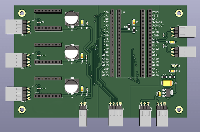
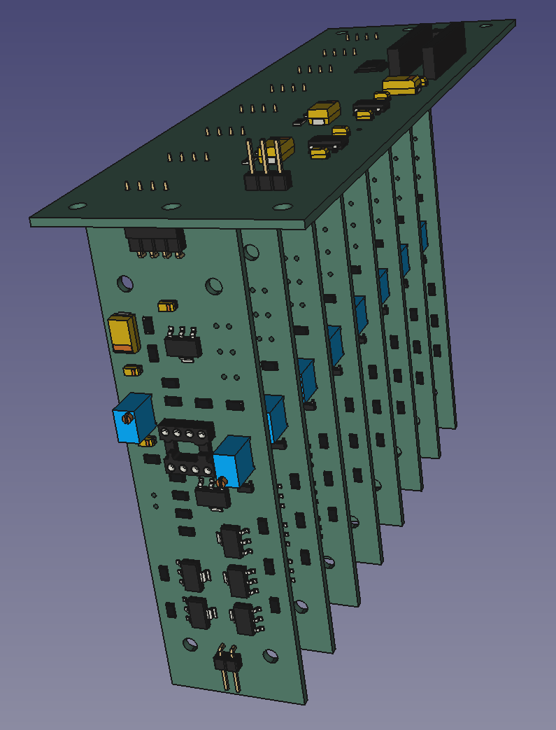
Here is the modular LED DAC/Driver described above in progress.

The top board is the DAC and I2C input (back of the board), front vertical header is for power supply input. The mating eight boards are the drivers (schematic and 3D view in post above). The connectors at the bottom of the picture are for each LED channel array.

Summary:
Inputs: Power supplies and I2C.
Outputs: 8 channels, each 16 bit, LED outputs.
Dimensions:

  • DAC 150 x 50 mm
  • Drivers 110 x 30 mm
  • Assembly 150 x 50 x 110 mm

Was able to get both boards routed over the weekend sprint, but will have to make time to complete the Pico/steppers board before sending all for PCB fabrication.

As I couldn’t see in the video - are those rotating or fixed?

The double nut locks the space for the lego-cones, and the cones are loose to rotate. Not perfect, but a good start.

Here is the master control unit (MCU) with some headers for use in other future projects.


Time to let it rest for a couple of days, and check later with a fresh eye.

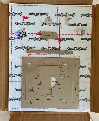
Sometimes it feels like Christmas in July. Just received the SendCutSend box with the laser cut parts.

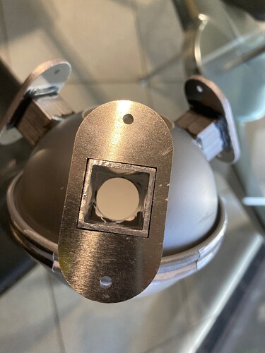
The large parts are plexiglass, and will become the top and bottom plate, with a couple of spacers between them. The aluminum parts on the top right are mounting plates for the LED PCBs, a small wrench to better tighten the dual nut of the posts (yeap, I made a mini-wrench) and a cap for the sphere port to go from round to a square, to reduce light scattering.

But the assembly fun will have to wait, heading out for holidays next week, and have a long list to catch on home projects before departing.

Also received this week all the electronic components. It was imperative to have them on-hand before making the PCBs, it is crazy how components disappear from one day to the next, and with long lead times.

Next steps, assemble the transport and begin integration testing software (protoboard is tested and ready), order PCBs (design is done, holding for unforeseen items in testing, and vacation logistics), assemble PCBs, and complete box design.

Caveat, you may have noticed that the transport does not a camera stand. For testing it will be using a Z stand on a solid surface, once things are buttoned up with testing, the mount will be part of the box which is not yet designed.

Stayed tuned… I am sure there will be some other unforeseen, but I am very optimistic on how it is going.
Thanks again to everyone for your suggestions and feedback.

1 Like

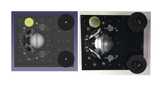
Not much happended in the last three weeks, but today… life imitates CAD!

Transport is not yet moving film, but all the mechanical pieces came nicely together. The mezzanine front/back bridges, and the M3 spacers between the mezzanine and the lower plate, significantly reduced the Plexiglas flexibility, even without a box to support it.

Installed the aluminum lasercut mount for the LED PCB at the sphere (epoxy glued to the ports), the thick aluminum should help with heat management on the other side of the heat sink.

The Sphere is cradled by the Plexyglass plates in the assembled unit.

Tension sensors now have the extension springs (silicone rubber bands), these worked great with the potentiometer hat design (pictured without film tension in the assembly).

Time to start working on the Pico software, have enough electronics in protoboard to control the three steppers, and the light. Stay tuned.

5 Likes

Nice and tiny design ! - your machine is starting to have soviet space program aesthetics :slight_smile:

2 Likes

Small progress, the initial testing of the transport components working together, controlled by the Pico is going well.

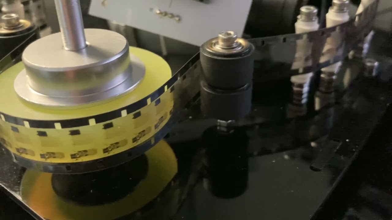
This video shows the supply and pickup working and holding tension, and the capstan moving the film precisely. Scanner is running with the short-pitch 7.605 mm, the capstan steps (with the TMC2208 micro-stepping) are 15,346 per frame! Snailing slow, as expected.

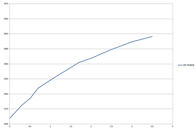
Here is the resulting test of the dancing-pot tension (using a spring-scale for calibrating).

The potentiometers are wired mirrowing eachother, what keeps the log curve about the same for supply and pickup (using log potentiometers, what I had). The tension used for the video is 1N on each side.

One item unexpectedly found was that the Pico ADC external reference is somewhat particular. When applying the 2.5V reference, common to the potentiometers, the Pico was having power-up issues. The problem is that it uses a small resistor (R7) as bridge between 3.3V and the VREF, and the 2.5V was affecting it. This is referenced in the Pico datasheet, and as suggested there, for this use case is was best to remove R7, with the added benefit of isolating the ADC reference from the 3.3V digital noise.

Thanks @friolator for the reference to Imagica. Based on the initial results, while SnailScan is extremely slow, should be 5 or 6 times faster.

Thanks @robinojones. The transport (without the camera) has a similar form factor of a tape reel. The motors are spaced to accomodate 7" diameter reels, which I have a few of 8mm. The video shows 3.5" diameter reels for the 16mm film.

Thanks to everyone for the feedback, small steps (snail steps :slight_smile: ). Stay tuned!

3 Likes

This is a rough capture, but first one where all the pieces are linked.
The Pico is connected via USB serial to the Raspberry Pi, which controls the transport and led via serial commands.

When testing single captures, the frame length was adjusted until it did not shift away after several frames. There seem to be a shift from one frame to the next, and as seen in the video, these appear to be cyclical over several frames.

I have to think about what is causing these, thinking of an issue with the transport, but there may be a contribution on the spacing of the perforations.

This is 16mm from the 50s, so I wonder if the pattern of the shift has a contribution of uneven perforations… probably not the case, since the edge of the picture does not change.

PS. Forgot to mention that the 100:1 gear steppers were replaced for 14:1, providing a bit more speed while keeping the number of steps for the smaller frame (regular 8) to about 900 per frame.

probably not. The super 8 issue is specific to that format, and is about the position of the perf relative to the frame edge.

I wonder if the issue here is just film shrinkage.

1 Like

I assume that you are referring to the cyclic shift on the left, unstabilized footage? If so, have a look at the raw image (also on the left) I recently posted in another thread. This cyclic shift is caused by the bad design of my own scanner. Film is advanced by a sprocket wheel taken from an old S8-projector. I think the reason is that the placement of the sprocket have a slight variation which transfers to the cyclic shift seen. There are other issues which might contribute: first, there is a noticeable amount of film between the sprocket wheel defining the capture position, second, the sprockets are smaller than the sprocket holes - so the tension in the film is important. I ended up designing a sprocket-registration algo - of course, using a daVinci-tracker is also feasible.

I am aware that your transport system is very different, but the similarity is striking…

1 Like

Thanks @friolator. There may be some shrinkage in the film, but the cycle of the movement is about 20 frames and it is a small reel, so it doesn’t correlate to it physically.

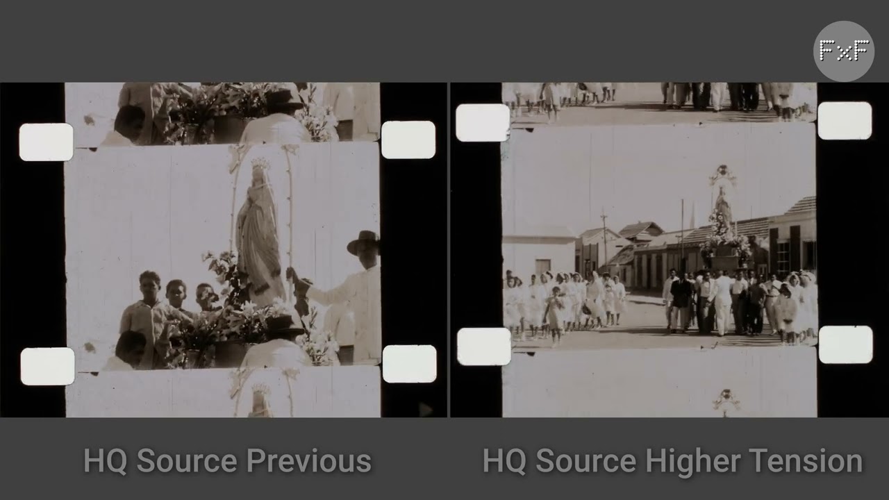
Yes, the left side is straight out of the HQ file sequence without stabilization. Right side is stabilized with Resolve tracker.

Good pointers to explore. I currently have very little tension, and will look into experimenting with the tension settings. Indeed the movement of yours and the above have a striking similar beat, but I have no sprockets wheel whatsoever.

I am going down the same route. Thinking about something very simple to provide sprocket position feedback to the Pico first, then do the stabilization in post.
Your posting and shared github implementation are a great starting point.

I am puzzled by the similarities of the unwanted movement. Certainly SnailScan is quite far from perfect, and there is much room for improvement.
In this new test, I made some adjustment to the level of the reels heights to reduce a bit of lateral displacement of the picture (vertical displacement of the film), and to see if there was any change, increased the tension setting for the supply side, and pickup side. The tension made a slight difference in the long term trend (shifting upward in the picture), which can be tuned by the frame length.
What puzzled me is that the up-down wavy motion is fairly repeatable, even scanning a different portion of the film.
On the hypothesis that there may be slight changes on the perforation distance, I scanned a different portion of the film, and synchronized the two portions, starting at a close point on the film markings.

It is possible that the scanner transport problem coincided, but I was a bit surprised that the movement direction is somewhat parallel for the two films.

In an effort to isolate the possible root cause on the scanner, I plan to do some additional testing changing one variable for each, and determine if there are any that make it worst or better.

Thanks to all for your feedback, and insights. Stay tunned.

The motion looks like a sort of cam action on an eccentric axis to me. This is just a guess using the dimensions available in the footage.

Since this is 16mm film with a frame height of 7.49mm, measuring from the footage, the little dip is about 0.79mm each time.

And it looks like a full cycle lasts about 31 frames, which would make it every 232mm of film. If that’s the circumference of the cam shaft, solve 232mm = 2πr and get a radius of 37mm.

Does your film path have any elements with a radius close to 37mm? If so, the axis of rotation appears to have about a 0.8mm eccentricity in it.

That’s all just guessing, but it was fun working through the math, hehe. Good luck tracking down whatever it is. :smiley:

2 Likes

Thanks! @npiedgon.

Well… I think that’s exactly what it is.

The capstan wheel is 50mm, the diameter of the silicone encoder.
Other than the reels, it is the only item big enough.

The encoder to its 6mm axle is not perfect, but is not as bad as the result.

The problem is probably the rest of the assembly. The capstan wheel is mounted directly on the geared stepper axle with a 6mm to 8mm coupler.

The gear stepper axle has a bit of play, and under tension it may be a contributor.
The coupler is probably the most significant contributor to the eccentricity. This particular one I was not happy with, because both axel screws are angled 90 degrees, instead of 180 degrees opposite, like similar couplers.

May be able to improve a bit by replacing the coupler, for one with 180 degrees mounting screws, and tightening with equal torque on both sides.

Thanks for the tip, mechanics is not my area of expertise, so what it may be obvious to you and others was not trivial for me. Sincerely appreciate you taking the time to do the math and share this hypothesis.

Coupler on order, will have it by the end of the week.

1 Like

Out of curiosity, how round is that silicone encoder? That seems like the sort of part that has to be cast and not machined. Have you been able to confirm the 50mm diameter (say, with a pair of calipers) across a half-dozen or so points on the wheel?

Without a tolerance spec in the Amazon listing, I wonder if the half-millimeter might have simply gone missing due to the shape of the silicone mold… :grimacing:

Encoder measurements range from 50.14 to 49.94 diameter. As I mentioned prior, not perfect.
Turning it around the axel against a reference plane, its eccentricity is barely seen.

When turning the assembly on the stepper, there is about 1mm variation (not including the stepper axel play).

The 2/10 mm variation in the encoder would be a contributor, but I think the one-sided screws in the coupler shift the coupler axle, and are likely the most significant issue.

1 Like

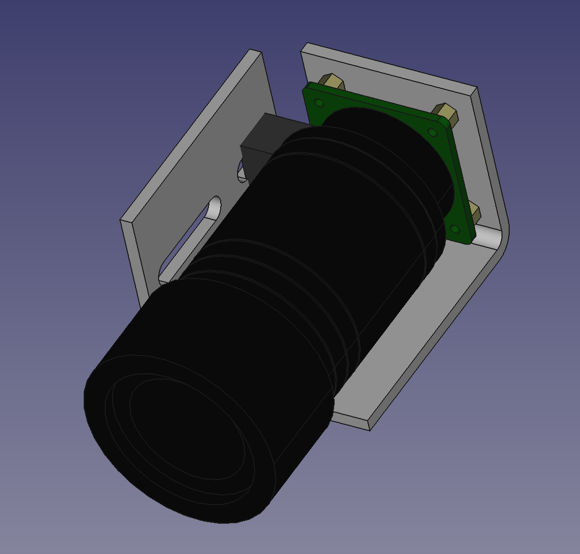
Got sidetracked in how to improve the camera mount. Given the direction of the film, the HQ mounting 1/4 inch screw would be on the side. Additionally, for 8mm film, the extension tube gets long, and the arm of the lens weight makes the camera prone to vibration.

This is what a possible side mount, with a mounting slot to the front of the assembly would look like

1 Like

I received the coupler with mounting screws at 180 degree of each other, previous couple had these at 90 degrees.

The following video illustrates a sequence taken with the previous couppler, side-by-side, with sequence taken after replacing the coupler. The new video is shown up-side-down, since the film is now spooled correctly.

The period of the movement observed in the frame sequences is close to 21 frames, determined by looking at the individual stills side.

For the math, the stepper gear ratio is 13 + (212/289). The TMC2208 driver is used at 1/16 micro step. The stepper is 200 per turn.

Update: For clarity 200 steps = 3200 microSteps.

SMPTE ST109:2003 indicates perforation pitch of either 0.2994 in or 0.3000 in (7.605 mm or 7.620 mm) for 16mm film.

The frame distance that worked best to hold position of the film is 7.54 mm which translates to 2109 microSteps (updated for clarity).

21 frames x 7.54 mm = 158.34 mm
158.34 mm / π = Diameter = 50.40 mm

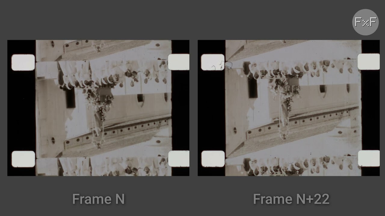
To confirm, the following the 21 frames periodicity, the following video is showing, side-by-side, frame n on the left, and frame n+22 on the right, on the same frame sequence (repeated 3 times).

Good illustration of how critical are the tolerances in a transport, and how these are mostly masked by the detection of the sprocket (directly or via software).

Great information for designing a software strategy to mitigate the low cost silicone encoder shortcomings.

Thanks again @npiegdon for pointing the cam movement.

Correction, initial posting had the values for 20 frames, corrected to 21 frames.
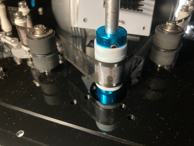
In an effort to confirm that the frame movement is the 50mm silicone encoder, I rigged a capstan stacking the 15mm coupler and wrapping it with silicone rubber bands.
I was concerned if the smaller surface contact would be sufficient to provide enough grip on the film, fortunately the film moves well.

Below is a test sequence with the above rig. Except for the last portion, which is camera stabilized with Resolve, all the other clips are without stabilization.

The earlier test was placed at 3.3 times the speed to confirm the beat is similar to the new smaller coupler.

Given the completely different capstan configurations, yet the persistence of the similar movement, I am leaning to think that the problem may be in the stepper-gearbox combination. The axle has a bit of play. Another hint is that the issue is stretched by the perimeter of the capstan, as confirmed by speeding up the 50mm sequence by the diameter ratio with the 15mm sequence.

Still not sure if there may be something else that could cause it, but have less confident than the issue was the encoder.

The good bit of news is that frame is only slipping a bit over a sequence of 300 frames. Good start for a digital detector/feedback of sprocket position.

1 Like