Very cool project! I’ve got a bit of experience designing LED lighting application for film scanning, so I’m curious about your driver topology. I’m having a bit of trouble following exactly what’s going on. Would you might elaborating? Seems like you’re using a DAC to set the sink current somehow, though I’m not sure I understand how exactly? Is there a reason you chose not to use standard driver with PWM or analog dimming?
LEDs are fast enough to follow the PWM signal. That is, there brightness changes from 100% LED intensity when the PWM is at 100% to something close to 0% intensity when the PWM is at 0%. Usually fast enough (several kHz at least) that your eyes do not notice, but a camera with a sufficient short exposure time will notice this anyway. Of course, you do want to avoid that.
If “Analog dimming” refers to the old dimming unit in AC circuits: they have the same problem, as they are working with chopping frequencies of 50 Hz (most of the world) or 60 Hz (US).
One way out is to have a truely analog current source; one way to implement such a thing is a DAC which drives a op-Amp paired with a beafy FET. An old schematic of such a setup can be found here.
The trick with PWMing a light source designed for photo or video purposes is to set the frequency high enough. Generally 25khz or above should be flicker-free for video and photo applications. The solution I designed used 30khz PWM, and there was no detectable banding on any captures.
The other alternative, analog dimmer, is a feature of constant-current LED drivers that limit the current based on a reference voltage. This would be a DC circuit, and its often as simple as just hooking up a potentiometer to a pin of the driver. I’m a fan of the TI LM3409, which offers both analog dimming and PWM dimming at very high frequencies via the use of a shunt-FET (the PWM signal drives the gate of a FET that shorts the output of the driver to ground in one of the signal phases).
Might be worth checking out since it can drastically cut your BOM size and cost, and reduce the size of the circuit footprint on the PCB.
Thank you @Alexi_Maschas for the kind comment.
Expanding on @cpixip, LEDs are fast enough to follow current variations (IL), and typically buck switching current regulators (like LM3409) produce a sawtooth current (see figure 10 and figure 11 of the Application Note AN1953 for the LM3409).
It is also true that the White LED Phosphor would be a low pass filter to high frequency current variations, but in general it has a fast response time, as demonstrated by this experiment.
Consider also that the clock frequency of the IMX477 may be as high as 27 MHz (Raspberry HQ sensor).
In short, current variations in the tens of nanosec order (very high frequencies saw tooth of the regulator), will be quantified somehow in variations of pixel values. These variations may not be visually perceived (no perceptible pattern in the resulting image), but these will be imprinted in the image (increased “noise”).
A bit purist? definitely.
Topology for Current (above schematic)
EDIT (after incorrectly posting).
This topology is suitable for mid-power LEDs (tens to few hundreds of mA), for higher current LEDs heat and power management may render impractical.
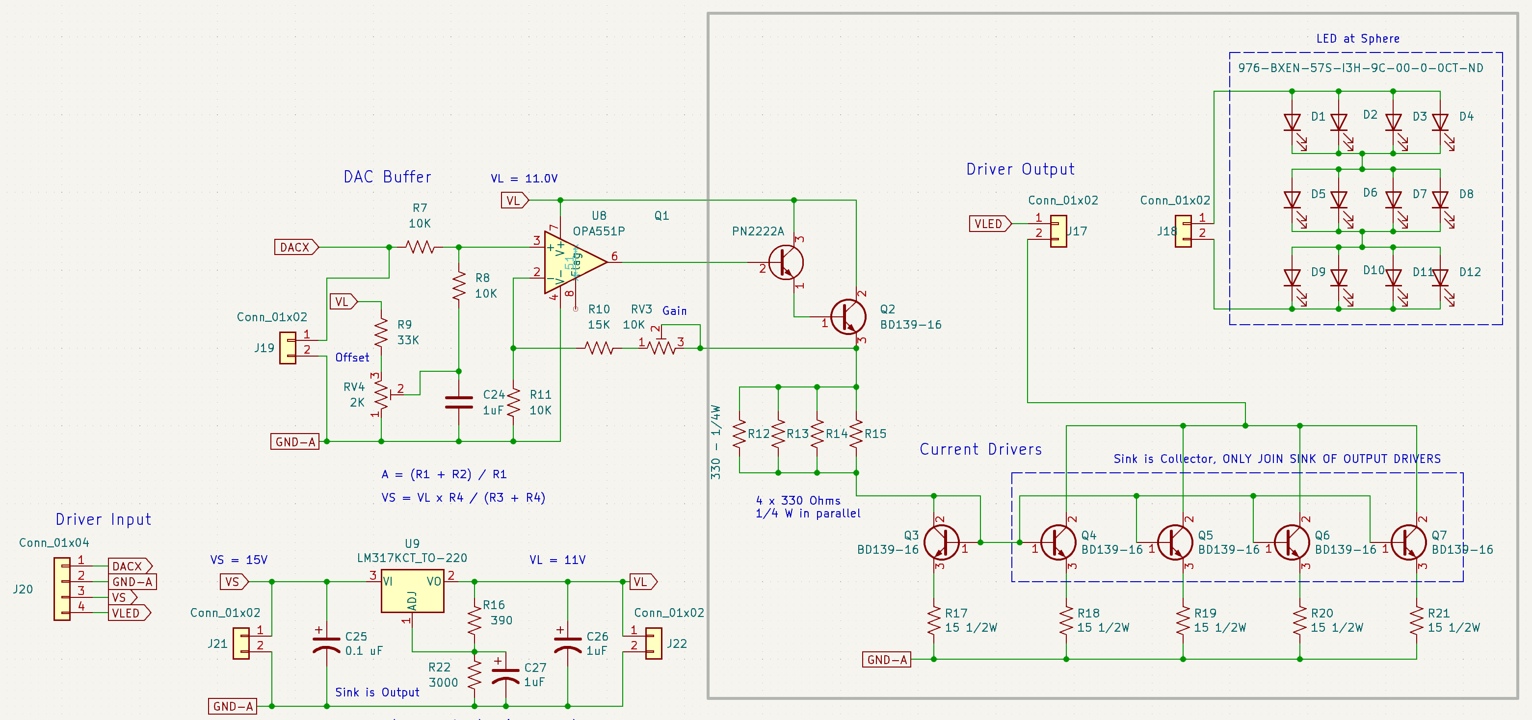
DACX is the output of the DAC, and provides 16 bit resolution in a 0 to 5V range. Similarly to the circuit referenced by @cpixip, the OpAmp + the darlington transistors Q1/Q2 are amplifying the voltage output of the DAC, and level shifting, from the DAC range of 0 to 5V to the range at the emitter of Q2, approximately 0.7 to 8V. The offset (bias current at the 0V of the DAC) is adjusted with RV4, while maximum output (gain) is adjusted with RV3.
That amplified/shifted voltage range is translated to a current range by the four parallel resistors, Q3 Base-Emitter, and R17. The current sensed by Q3 BE, is mirrored at the BEs of Q4 to Q7 and approximately the same at the collectors of Q4 to Q7: the current mirror. The resulting total current at J17 is the total, four times the current sensed at Q3 BE.
The topology has the advantage of lowering the power requirements to the transistor drivers (Q4 to Q7) to 1/4 of the total power.
It is worth clarifying that the White LEDs used are a bit unique, these have a Vf of approx. 9V and maximum IL of 100 mA, unlike the typical LED in a similar power range which would have 1/3 the voltage and 3 times the current.
For current mirror details and other configurations, this is a good overview reference.
2 Likes
Ah OK, somehow I missed that this was a current mirror. That was actually something I tried with my designs as well before moving the TPS92515 and then the LM3409 because of the difficulty of sourcing the former during the pandemic, but I was a little leery of the amount of heat that needs to be managed relative to the current.
I may be wrong about this, but I think you may be making your task harder than it needs to be. The pixel clocks in most sensors do in fact run at several megahertz, but that doesn’t mean that the sensor is actually reading at anything close to that rate. The pixel clock in a sensor is going to determine the bandwidth at which data can be read out of each pixel, but is not directly tied to the read out speed. This differs a bit between CCD and CMOS sensors, but essentially each pixel in a given row of the sensor will read at the same time (assuming a rolling shutter, global shutter sensors will read the entire sensor at once), and then after a short delay the next row will read out. You can see that illustrated here:
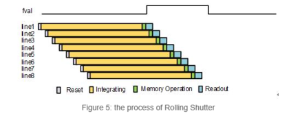
Where the pixel clock comes into play is how fast the data can be read out of the pixel. So let’s say you take am exposure at 1/1000th of a second, each pixel in the sensor will integrate for that time (a simplification here, since as I mentioned each row has a staggered start and end), which simply means its counting the photons that hit the detector. If the rate of the photons hitting the pixel varies within that time, the pixel is effectively blind to that. Once it has integrated for the set amount of time, the data is read out from the sensor to whatever is processing the sensor data, and it is at this point that the pixel clock comes into play, determining the bandwidth available for that readout, and thus the speed at which it occurs. There’s a fair bit of complexity here, with CMOS sensor using an ADC per pixel vs the CCD which has to buffer the entire sensor readout and wait on a single ADC, which is why CCD sensors have intrinsically lower frame rates, while still being able to take fast individual exposures.
You get into trouble with LED PWM is when the frequency is synced with the row integration times such that some rows get slightly more or less light over the period of integration. The other failure mode is if the frequency is slow enough relative to the exposure time, it can be either fully on or off during the entire exposure. The trick is to turn of the LED on and off so fast that it goes through multiple cycles during the entire integration time. At 30khz, for instance, while you might see problems if the shutter speed is very high or the duty cycle of the LED PWM is very low, for the most part the different in photon counts over the integration time of the exposure is going to be well below the noise floor of the sensor.
You are also correct that most constant current switching regulators are going to generate current in a sawtooth pattern, though its worth noting that there are several ways to mitigate this. The easiest is probably just putting a capacitor across the output, which in practice seems to smooth out the current spikes from PWMing the output as well. You can also design your application to minimize peak to peak current variation as well, though there are a number of tradeoff to doing this.
Anyway, if you have a working design there’s probably no hugely pressing reason to make changes, but I thought you might find this context useful. Cheers!
Thanks @Alexi_Maschas for taking the time to share this info. Agree that the parameter to consider implications of variations would be the exposure time.
Same here. The design with the current mirror first came about from the difficulty to source the common switching regulators around the pandemic. I was not familiar with these particular ones either.
The ones used in the popular boards however (fentobuck for example AL8805, and some other boards/ICs) had the particular inability to regulate below 20% of max current. A second deal breaker (part availability was first).
It hasn’t been hard, but maybe so. The LM3409 (as other buck regulators) have the similar limitations on deal with the low current segment of the voltage control (see datasheet Figure 12. Amplitude Dimming Using IADJ Pin, between 0 and 0.3), and that will not work well with mid/low current LEDs (100 mA Absolute Max in my case). Essentially the lower portion of the DAC 16 bit, which are required by the exponential nature of light perception, are truncated by the buck.
Undoubtedly the current mirror is -for me- a well known and tested topology. (first design round in this post around the pandemic).
In the context of mid-power LEDs with a rolling shutter stop-motion application, linear is as good as it gets, and is working well.
For other applications (continuous motion, global shutter, large current LEDs), the LM3409 and similar may be simpler, providing the issues (sawtooth and low current regulation) do not affect requirements, are managed, and/or mitigated in the context of the application.
Hah, looks like we took similar paths, since I also did a lot of early experiments with the AL8805 and ran into a similar problem. It’s definitely the case that the analog dimming implementation in many of these drivers has a lower limit, particularly with low and mid-power LEDs. That’s actually one of the reasons I went for high frequency PWM, since it’s very linear down to < 1% brightness. It was a difficult build however, since PWM pulses at that frequency have single ns transition times, and you have to be very careful routing the lines and the ground pours to manage noise. One of the reasons I went with the LM3409 was that TI has published a reference design for a multi-channel, high frequency, high resolution PWM and analog dimmable board using that IC here: TIDA-01415 reference design | TI.com. So if you’re ever tempted to go down that road I’d recommend checking that out.
I think one of the most appealing things to me when I was assessing current mirroring was the fact that my implementation drives a grid of LEDs which are laid in a parallel/series fashion. So each row has 8 LEDs, and each channel has three rows with one driver per channel. As you may know, the risk here is that as the LEDs get hot they can tend to draw more current, and not every emitter responds in a uniform way so one string can end up in self-reinforcing loop where it goes into thermal runaway. I haven’t actually run into this problem, mostly because I think my rows have enough emitters and I’m using an aluminum PCB to spread the heat around, but I definitely considered using a current mirror to mitigate this possibility.
Anyway, it’s a very cool design! Love to see what other solutions people have arrived at for these purposes. Out of curiosity, what are you using the lower brightness levels of the emitters for?
1 Like
Thanks for pointing the reference design, very helpful.
One of the goals is to perform testing of White LED + Colors LEDs. The color LEDs when mixed would need lower brightness down to zero.
A recap of year+ in the life of SnailScan2
Moving film is hard… Moving small film without sprockets or hole sprocket detectors is… harder.
A few weeks back, the scanner was finally good-enough to do a 50 ft. reel of film, unattended. It is nowhere near a finished product, specially on the software side… but it can finally produce great quality results.
If you previously read about this project, the film was moving in ways different that one would expect. It became one of the hardest things to overcome, to have a more predictable and stable scanning.
Following is a quick recap to share much of what transpired in the past year plus.
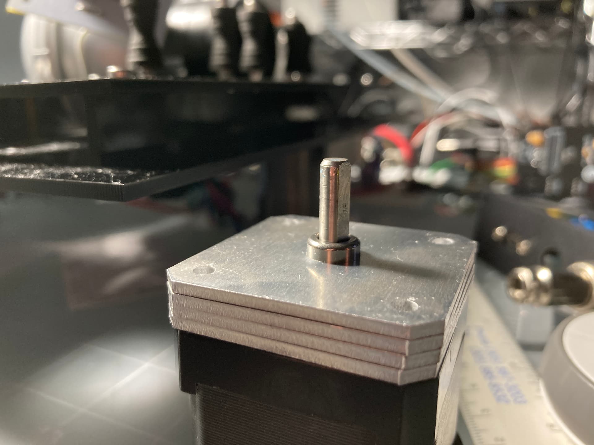
Steppers
Initially the project used geared steppers, and a significant contributor to the unexpected film movement was the backlash of the gears. Replacing the geared-steppers with regular steppers then required smaller steps (more micro-steps) still it was possible to get these from the driver. The project has been using the TMC2208, and to access 256 micro-steps on those, it was necessary to control them via the UART. The bit-banging of the unusualTMCs protocol was another project in itself, but it open up additional possibilities of control and information about the drivers.
The reels are supported directly by the stepper axles, and more than the geared motors, the regular steppers had significant axle play. It was also necessary to adjust the vertical position of the stepper, to match the transport height. To improve, a solution was to have some aluminum spacers fitting a cup-needle bearing to stiffen the axle a bit.

These two changes addressed one of the highest contributors of the unexpected movement.
Tension Sensors
The project uses dancing guides, pulled by silicon rubber, on a potentiometer axle. The original potentiometers were of lesser quality, the shafts also started to show signs of play.
A new quality part sourced as replacement had a slightly different knurl in the shaft, and while updating the “hat” it was a good opportunity to set the silicon rubber attachment point at a slight angle.
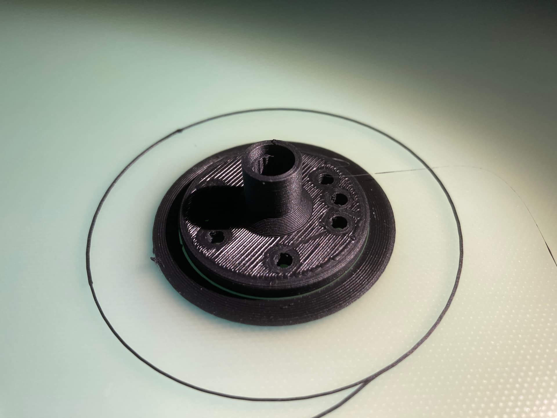
Replacing the potentiometers improved significantly the quality of the readings, the mechanical stability, and had a small incremental improvement in the unexpected film movement results.
Additionally -and related- improving the stability of the PICO ADC voltage reference was just as significant, if not more. In addition to prior improvements to the ADC (removing R7 on the PICO), the PICO now has a better reference.
PCBs
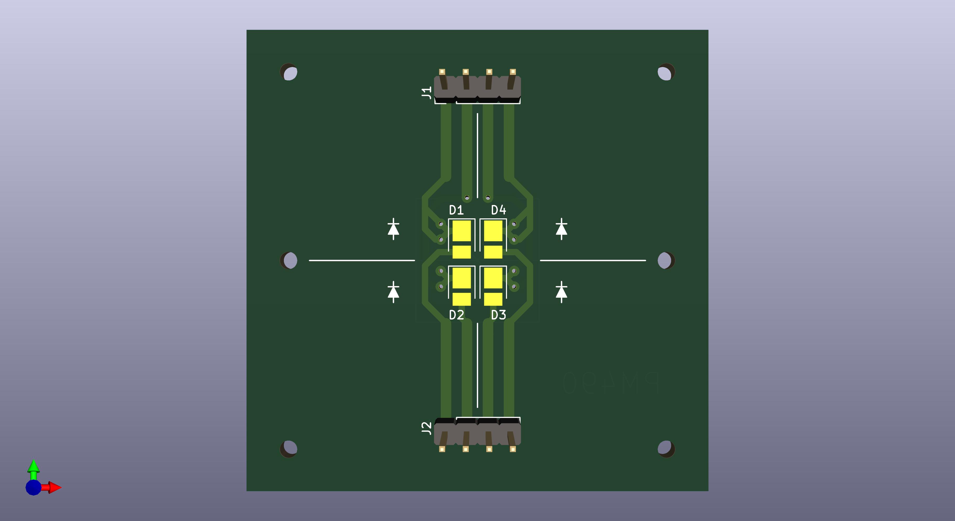
The PCBs designed late 2023 were ordered and built. And as part of building these, it was necessary to rig an SMD soldering plate, which actually ended up being an SMD soldering toaster.

The project LED driver had being previously redesigned to use mostly SMD components, and provide the flexibility to accommodate future LED configurations.

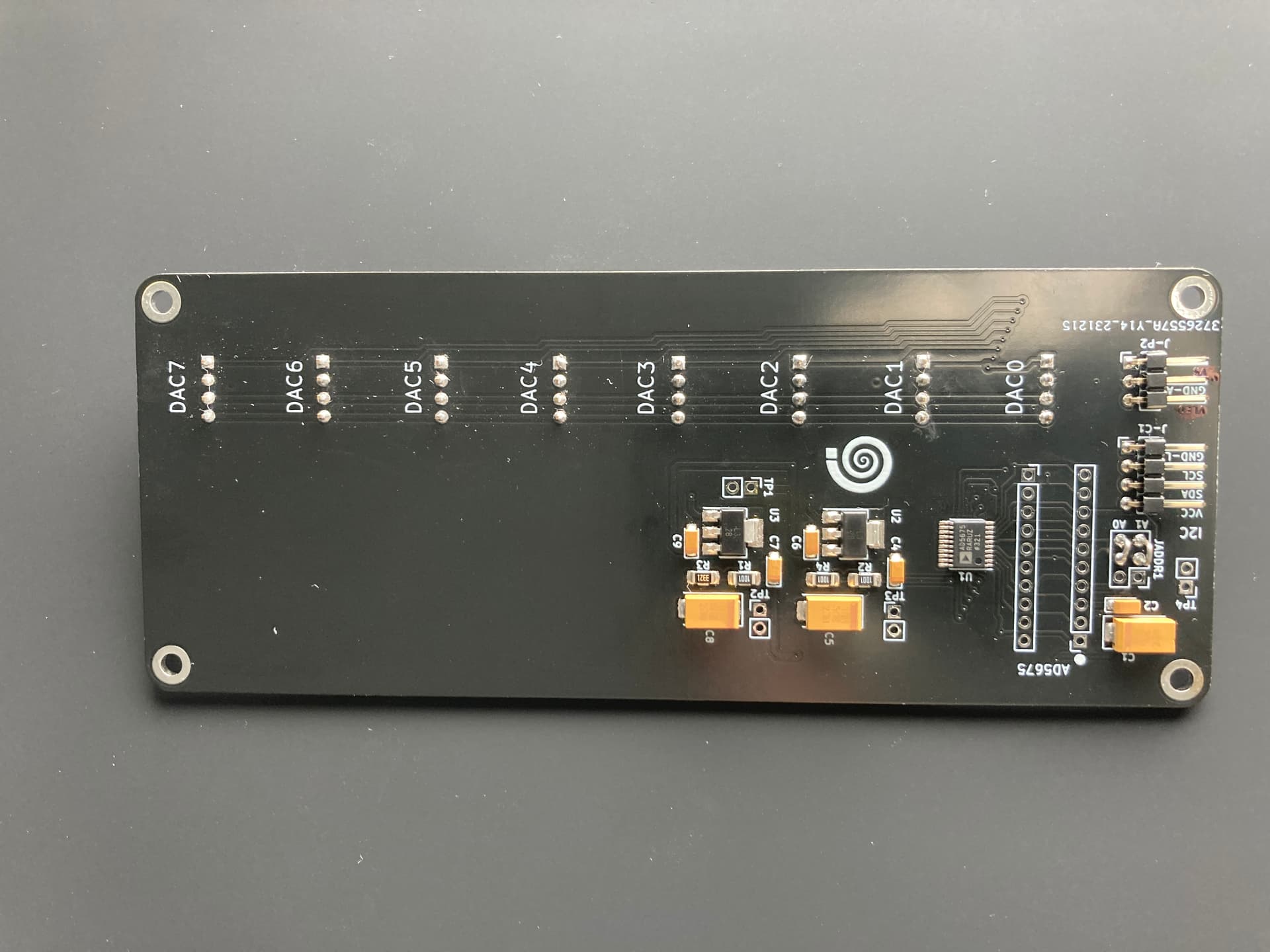
This setup results in a 16 bit Digital control of the LED intensity on a constant current driver configuration.
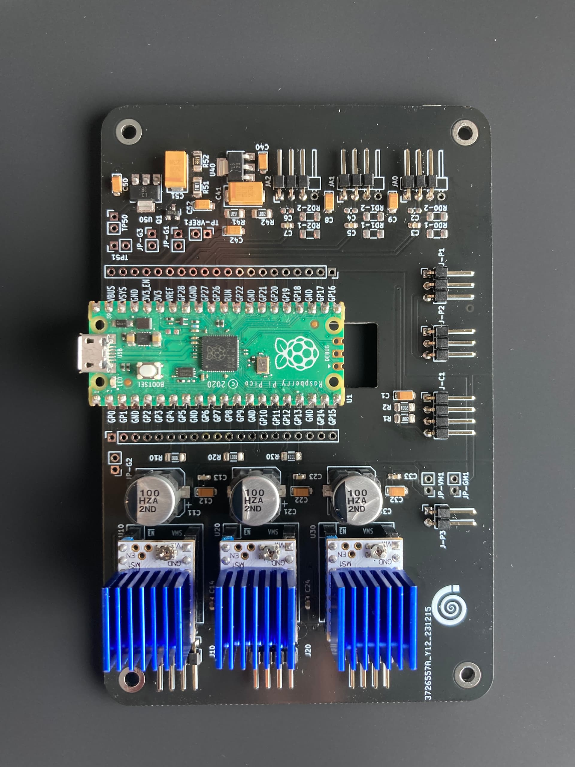
The MCU PCB holds the PICO, three stepper drivers controlled via UART, the ADC reference and conditioning, and the output to control the DAC.
F-Code Protocolling!
I just made that up, but in order to keep sanity on the transport control, a simple Protocol was created to provide/get anything that goes through the PICO, and between the PICO Cores… see next.
PICO C Code
Another finding in the search for the unexpected movement result was that Core 1 of the PICO services also the USB serial communications, and in doing so, it spuriously changes the timing of the ADC reading. For more details, see the exchange in the Raspberry Forum. https://forums.raspberrypi.com/viewtopic.php?p=2221107#p2221107
With the ADC providing the tension reading, and with the need for smaller micro steps, the requirement was cycles in the tens of microseconds, and this find was very significant. The project does not use the PIO, in part, to maintain linear motor control, and timely and accurate cycles are necessary.
Given that the PICO does have two cores, the time critical functions were then moved to the Core 1, leaving Core 0 to handles slower/non-critical items such as USB communications, and LED I2C communications. Time critical items are now solely on Core 1, including ADC (tension reading) and Stepper control.
Another finding was that the PICO execution speeds improve greatly if the code is run in RAM. A significant improvement on the time-critical functions was realized by using __time_critical_func() to instruct the compiler to load these functions into, and ran them, directly from RAM.
Spurious ADC timing was yet another significant contributor to odd/spurious unexpected movement results.
3D Printing
Somewhere in the past year, a beaten Ender 3 needed an overhaul and a foster home, and that facilitated crossing out some items, such as the redesign of the tension hats, mounting for the PCBs, and hoods between the sphere and the lens.
And…
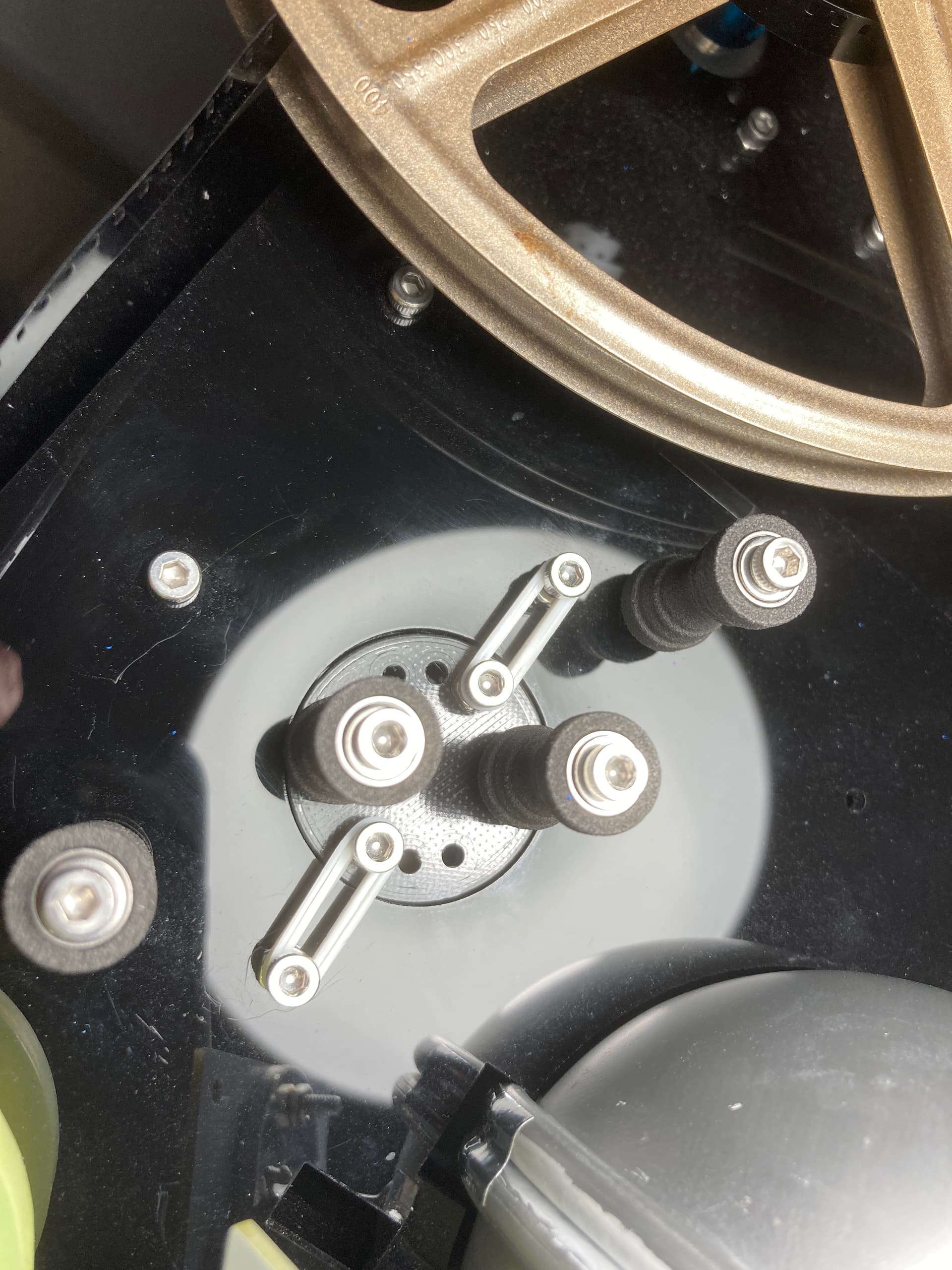
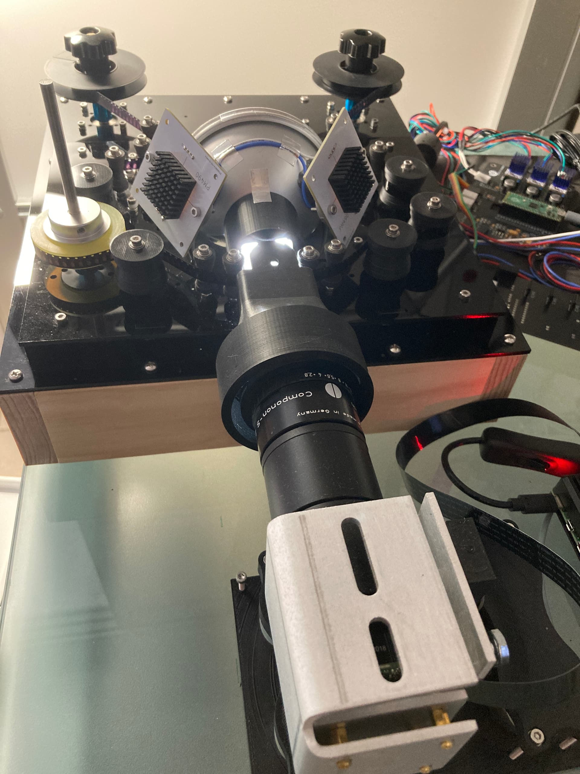
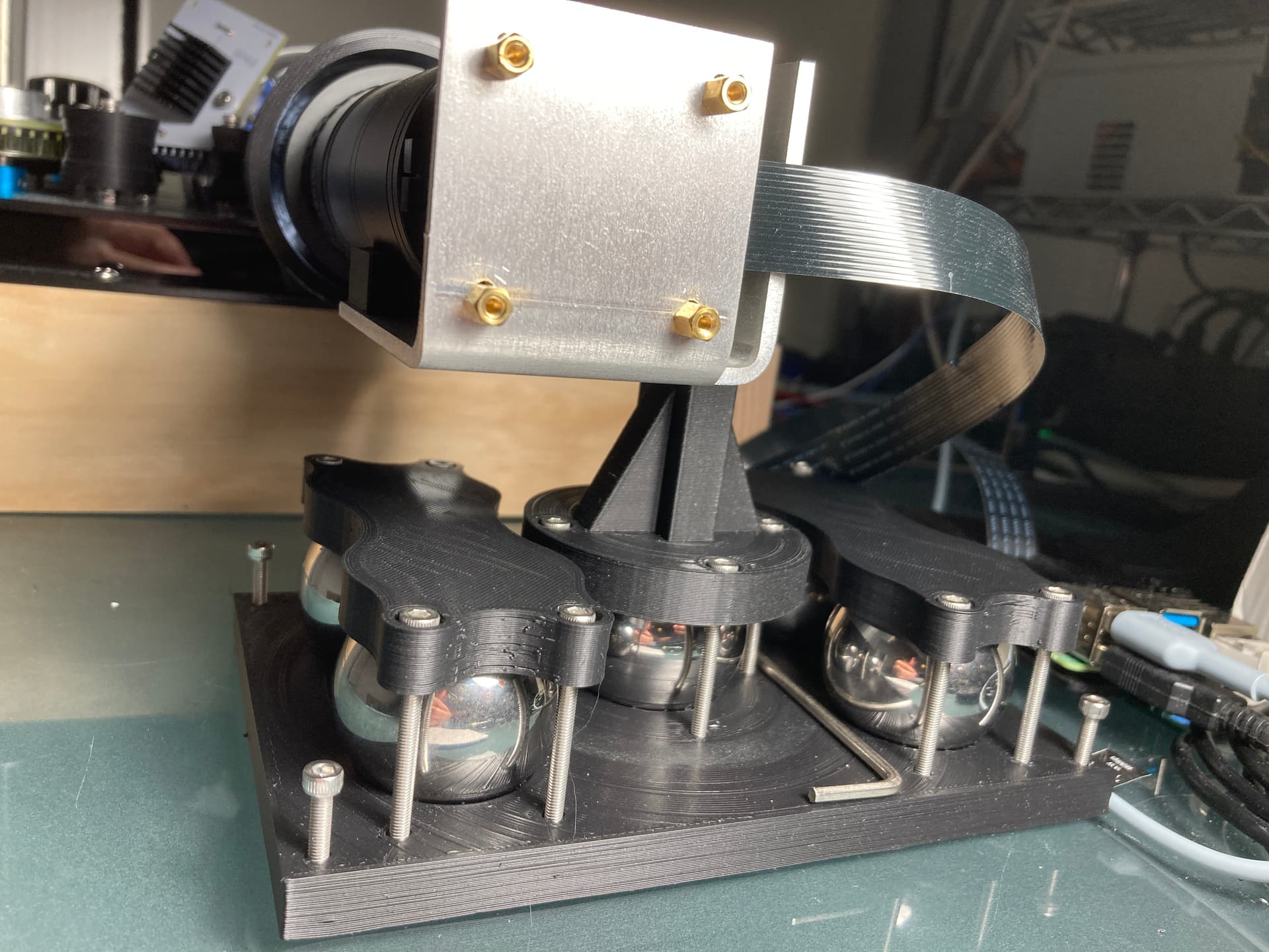
The Camera Mount
Anyone working with 8mm knows that one’s scanner is a unique vibration seeking device. Regardless of the nice aluminum custom piece (previous postings), the camera stand was less than ideal.
On the other hand, 3D printed parts were too light to keep everything from vibrating or moving.
Looking for ways to make the camera stand as heavy as practical, 38mm steel bearing balls were affordable and small.
A widely used camera mount is the ball head… so another solution was using one of the steel bearing balls as a ball head for the camera arm, with M3 thread screws providing very fine adjustment for the the camera roll and pitch axes. The bearing balls came in pack of 5, the other 4 were use to increase the weight of the base.
Raspberry Pi (4B) and HQ
It was finally time to learn the particulars of the HQ sensor, Raspberry Pi, Python, and some kind of minimal work reference GUI to integrate the existing modules into a workable scanner.
A key design constrain has been the ability to scan16mm, Standard 8, and Super 8, with minimal or no transport changes. In order to do so, the transport is sprocket-less, with detection and feedback of the film position extracted from the sensor image.
The HQ and Raspberry Pi 4 is a less than ideal combination for this purpose: limited processing power, and limitations of frame-rate at higher resolutions.
With the mind-frame of working with separate cores with the PICO, it was natural to reduce the overhead of processes launching across different cores, by associating processing hungry or time consuming items to a specific core.
To that effect, the camera loop would run on core 3, the raw pipeline on core 2, and transport control and file-saving on core 1. The RPi4 is running headless, so there is a bit of overhead on the VNC, the GUI, and the waveform monitor, but these processes were left without a specific core association.
Rawer than Raw
Capturing a raw array (not the same as capturing a raw/DNG file) provided an alternative to stabilize the capture to the sprocket hole horizontal edge and the film vertical edge, a work around to the challenges and limitations of the transport. The work is in itself a deep rabbit hole, and this post provides much of the journey. Raspberry HQ - capturing or extracting raw values
The result is the RGB values binned (2032x1520 with R/B at 12bit and G at 13bit depth) of the raw capture, and after cropping results an uncompressed TIFF (1900x1300). As described in the posting referenced, the TIFF is a representation of the sensor values, and requires a color processing pipeline that is performed in Davinci Resolve.
A process to create a synthetic color from the active area of the film was used to greatly simplify balancing of the resulting TIFF.
Scanning Run
A good reality check was to scan 35 reels (50 ft. each) of Super 8.
At present, the RPi 4 saves via Ethernet to a NAS, and it does so at about 24 frames per minute, about two and a half hours per reel. Certainly in keeping with the project name!
None of these films I had scanned previously, these belong to a family member. Post capturing processing was done using the synthetic target and color processing pipeline in Davinci Resolve. No image stabilization or noise reduction was performed in post.
The deliverables look fantastic, here as a framegrab of the final MP4 video (3840x2160).

More work
Much clean up is needed in the existing code, and there are some areas that need additional work, including:
-
Completing F-Code commands and improvements on the PICO firmware.
-
GUI for operational settings (light intensity/film format).
-
Sprocket detection/capture stabilization improvements.
Development tools for special cases
There is also one Standard 8 film that for unknown reasons virtually has no red component. I am uncertain if it is the result of exposure, development or both. This particular film has a scene that has a unique cultural value.
With the goal of making the best of challenging conditions on the scene/film, the plan is also to improve the modularity of the capture code to allow each color channel to be captured at different light setting. Additionally to have the option to implement individual channel stacking and provide a lower noise and increased bit depth separately for R, G, and B.
Needless to say, this planned mode will trade much capture time for what I hope would be noticeable scanning improvements for film with special conditions.
It worth highlighting that since the scanner is now running without gears, it is quite easy to position and scan a single scene in the middle of the film. So the intention is to do separate exposure and stacking for only the content that requires it or is worth the extra time and effort.
For now… That’s all folks!
6 Likes
I love big info-dump posts like this one. Thanks for sharing! That looks like a lot of great progress.
This is curious. Did you mean they move axially? Like, they pull out or can be pushed in a little? I’ve never had any trouble with stepper play before. And once things are under tension, is it still a problem?
With a gearbox, backlash will remain a problem because the film tension won’t be able to overcome the torque in the gearbox. But without one, you’re pulling on the shaft directly and–at least on my machine–once it’s under tension, it seems to eat all of the backlash automatically. Did you have a different experience?
Those PCBs look great. I like the little waffle-iron thing, too. Using a hot plate to solder an entire board at once feels a little like using a cheat code. ![]()
Did you mean you made your own set of commands here? This feels like one of the things that don’t seem to be talked about very often here. Granted, a protocol will be very device-specific, so maybe there isn’t much reuse to be had by sharing. But, I’m still interested nonetheless! I’ve been meaning to share more of my code and the little (MIDI-like) protocol I developed for sending commands out to my Arduino was one of the more fun pieces of code to write.
This feels like a critical feature. The exposure times for my color channels are wildly different (especially IR, but that’s a different story). I bet you will discover that there is at least a little red in that regular-8 film after all, it’s just hiding way down at the bottom of the signal!
All of this is great work and I can’t wait for the next update.
1 Like
Thanks @npiegdon
The axel has a top and bottom bearing encased in the stepper. There seem some slight lateral movement (no up down) when under tension, the lateral displacement may well be within the stepper bearing tolerance. For clarity, if we take the stepper axel itself as the z axis, the displacement would be in the x-y plane.
Notice that I have a long axel attached to the capstan, so it is hard to even notice with the small length of the stepper own axle and the reel on it.
I took advantage of the spacers (needed after removing the geared steppers) to include the cup needle bearing and there was an improvement.
Without gears the backlash is gone. However, keep in mind that the film is held to the capstan only by surface friction with a silicone encoder wheel… not ideal.
![]()
One still has to place the components, but yes, it makes a world of difference.
Yes. In this posting I made up the F-Code drawing from G-code analogy, but it is not anything that complex. It started as commands to control individual components for testing, and it is evolving.
The commands are human readable, with a start of command character [ then two characters for the command, an optional argument(s) and an end of command character ].
If the command is time critical, it is pass-thru the second core for execution.
For example:
To move supply counter clockwise 10 steps, the command is [S<000A]
To enable the capstan driver [CE]
To disable the capstan driver [CD]
To get the pIckup tension is [IG]
To set (put) the sUpply tension to 0x0080 is [UP0080]
To set (put) microsteps, arguments are Capstan 2^0, Supply 2^1 , Pickup 2^1, the command is [MP011] to read (get) is [MG]
All commands are blocking, so the PICO waits until the command is completed to provide the result via USB-Serial, and then accept a new command. The reply string length is dependent on the command, with a variable length block delimited by { and }
I have not yet coded some commands that I would like, but for scanning, I sand-box movement maintaining tension in the form of [SB0555] to move 0x555 micro-steps of capstan maintaining tension on supply and pickup (with the micro-steps setting of the driver). It is presently the only command that moves all steppers based on tension.
In its current form is a bit raw, but it is very functional and has potential.
Keep in mind that in my case I am with a Bayer.
In essence the code part will use each color channel (and corresponding pixels) as its own little monochrome sensor, with the band defined by the product of the illuminant and the Bayer filter, and the intensity of the illuminant set individually for each.
Colorful Steppingstone
This is also being done as a wildly colorful steppingstone for future multi-narrow-band capture. The idea is to take advantage of the Bayer limitations (the filtering) to capture multiple narrow band LEDs, at a minimum two, concurrently.
With 7 narrow band LEDs, two reds (nR1 nR2) one red-orange (nRO), one cyan (nC), one green (nG), and two blues (nB1 nB2), it is possible to capture all 7 bands, each with a unique light setting, in 3 captures.
- First capture nRO and nC
- Second capture nR1 and nB1
- Third capture for nR2 nG nB2.
On the last capture of three channels, nR2 is the highest wavelength and nB2 the lowest wavelength, keeping these out of the green Bayer band that will capture nG.
The same setup can also capture wR, wG and wB using three intensity settings of the white led, where the wide X band is defined by the Bayer filter.
Needless to say, it is done at the expense of the fractional spatial resolution available to each color channel, but my crystal ball says that Bayer sensors will increase speed and resolution so it would not be an issue in the future.
This wild idea (multi-spectral-DIY scanning) is already supported by the 8 channels DAC board (and the F-code protocol ![]() ), the hardware part missing is building the illuminant (sphere?) PCB(s) to accommodate all these LEDs.
), the hardware part missing is building the illuminant (sphere?) PCB(s) to accommodate all these LEDs.
1 Like
This may be a dumb question, but in the LED section, you have 3 series connections between 4 LEDs that are wired in parallel. In my limited experience, it’s generally not considered good practice to wire LED’s in parallel if one wants equal luminous intensity. Looking at a few data sheets (LiteOn and Wurth), both show nearly vertical forward current versus forward voltage, ie a tiny change in Vf results in a big change in If. Both have graphs showing luminous intensity as a function of If, and that curve is approximately a 45 degree angle (at the nominal operating current).
I think I understand the rest of your design, i2c control of illumination levels using digitally controlled If, instead of PWM, that is very nice, I’m just a bit unclear on the parallel wiring aspect. I get that series wiring would result in needing substantial voltages, which may be less desirable than what may be minimal illumination variations between the LEDs in parallel.
1 Like
Thanks for looking into my design. There are no dumb questions… cannot say the same about my answers ![]()
Short answer: generally, I do not disagree. Actually, with high intensity the main issue is the risk for thermal runaway among the parallel LEDs.
Long answer: there is more to the particulars, so it is a great question.
For context, the LED PCB has 4x ~1W White LEDs, cathodes and anodes separately routed to two 4-pin connectors, with the LEDs clustered together.
In the first iteration of the scanner and Driver -using the same PCB x 2- the topology was to drive one string of LEDs (two PCBs, one LED of each, in series) per transistor, the best practice… lots of wires.
Let’s look at these LED charts:

In this case, current is controlled, so the total current would be divided among the four LEDs in the parallel topology, and the voltage is one and the same for all four, so will be the current, which will be divided (1/4) from the total of the parallel. If all four LEDs have the same Voltage -with a not so steep If to Vf particulart to these- all four will have near the same current, and therefore near the same relative luminous flux. Although near is not equal, it is a tradeoff for simplifying the wiring.
Let’s also look at the other particulars:
- White LEDs, the actual LED is exiting the phosphor.
- LEDs used are of the same bin/production batch.
- Four LEDs are closely clustered together in the PCB at near equal temperature. Shifting importance to the total.
- Three PCBs are integrated with the sphere.
In this particular design/situation, if there were any small differences among the 4-LEDs It would be unnoticeable.
I did separate the LEDs, in the earlier version of the driver,
As you mentioned there is a need for substantial supply voltage, even with some in parallel. One unique consideration of these white LEDs is that their typical Vf is around 9V, which limits the ability to use many more in series.
On the newer design -with three 4-LED PCBs- I opted for wiring simplicity and changed the topology.
If I ever get to a new PCB for the LEDs, which would include color LEDs, would consider adding a very small resistor in series with the LEDs that will be in the parallel topology to further minimize the risk of thermal runaway.
Let me know if all that made sense, and thanks for bringing up the luminous intensity concern.
1 Like
Nope, everything you said made perfect sense. With a 9Vf, you would definitely need a fair amount of voltage. Out of curiosity, what is the respect lumen output of the various color LED’s.
I’ve scrolled up and it looks like I’ve missed a number of the items you have been posting. It looks like a number of the items are machined. Do you do that yourself, or farm it out? I like your pico base board. I am in process of doing a variation of the Tscann (Torulf in Sweden) board, but with the TMC2209’s. The folks over at Alt-scan have built a pretty nice interface / update to the the original one writtn by Torulf. I’ll like be looking at your stuff in more depth.
One thing, on your ball mount, I’ve done numerous design of kinematic mounts. One word of caution, as you adjust the screws and clamp down, there is increasing friction at the ball swivel, so each subsequent tightening requires more effort to make a small adjustment. You have probably figured this out already
I purchased -but have not yet started using- color LEDs with same pcb form-factor (2835), and similar current range 120 mA, to the white LEDs. The Vf is typical of color LEDs (2-3V).

Life has gotten on the way, multiple times, and haven’t had much bandwidth this year. Hope that I can do a summer sprint and show more progress.
No machine parts… yet. Everything is laser-cut or 3D printed. Maybe you are looking at the yellow silicone roller, that is a standard encoder wheel.
Thanks. I plan to share the design of every item of the project. PICO PCB hardware will probably not change, it is only pending to finalize the PICO firmware.
The Tscann is a great mature design. Since you are in the US, consider laser-cutting the top plate holes, I did the top plates(plexiglass), and it made it quite easy to assemble. I used sendcutsend, and they also offer materials.
There are a number of items that can be improved in the electronics of the Tscann8. Be sure to use the right capacitors for the TMCs (low ESR for the 100uF) it is a significant difference in performance (and price of the component).
Understand that Tscann uses the A4988s… is there that much difference to require a new PCB?
If I am not mistaken, the TMC2209 driver boards would also work on the PICO board as I designed it. One notable difference is the corresponding setting on the micro-step configuration pins (MS1 and MS2). However, in this project/board the micro-stepping selection is done via UART. The other difference is the SPREAD pin, but most driver boards do not present it to the headers.
I started with the TMC2208, and thought I could drive the motors with a 36V, which the 08 supports (the 09 Vvmax is 33V). But the 08 gets very hot, very quickly (at least the cheap driver boards I have). So brought the voltage for motors down to 24V, which would also work for the 09… so it should also work.
It is a great and fairly mature project, and has been replicated well.
Thanks, I did notice. PLA gives a bit of play, and it works well for the tiny adjustments required.
As you probably figured out, mechanical design is not my strong suit ![]()
I hope that the future will bring a better camera sensor for the project, and maybe then will work on something better.
I plan to publish everything on the scanner but are not there yet. Happy to share any sections/files/component in advance of publishing if needed.
Quick rundown comparison of key differences to Tscann8:
- 8/S8 and 16.
- Minimum film contact (no gate, all rollers have bearings).
- No sprocket hole hardware sensor detector. Precise film movement + software detection and correction from captured image.
- Programmable supply/pickup hold tension.
- Programmable light intensity, high CRI (98+) white LED.
- Silicone friction-only capstan (the main film contact is the yellow encoder wheel)
- PICO based hardware controller.
- Film transport and light are controllable with any USB-Serial capable device (RPi, Windows, Mac, Linux).
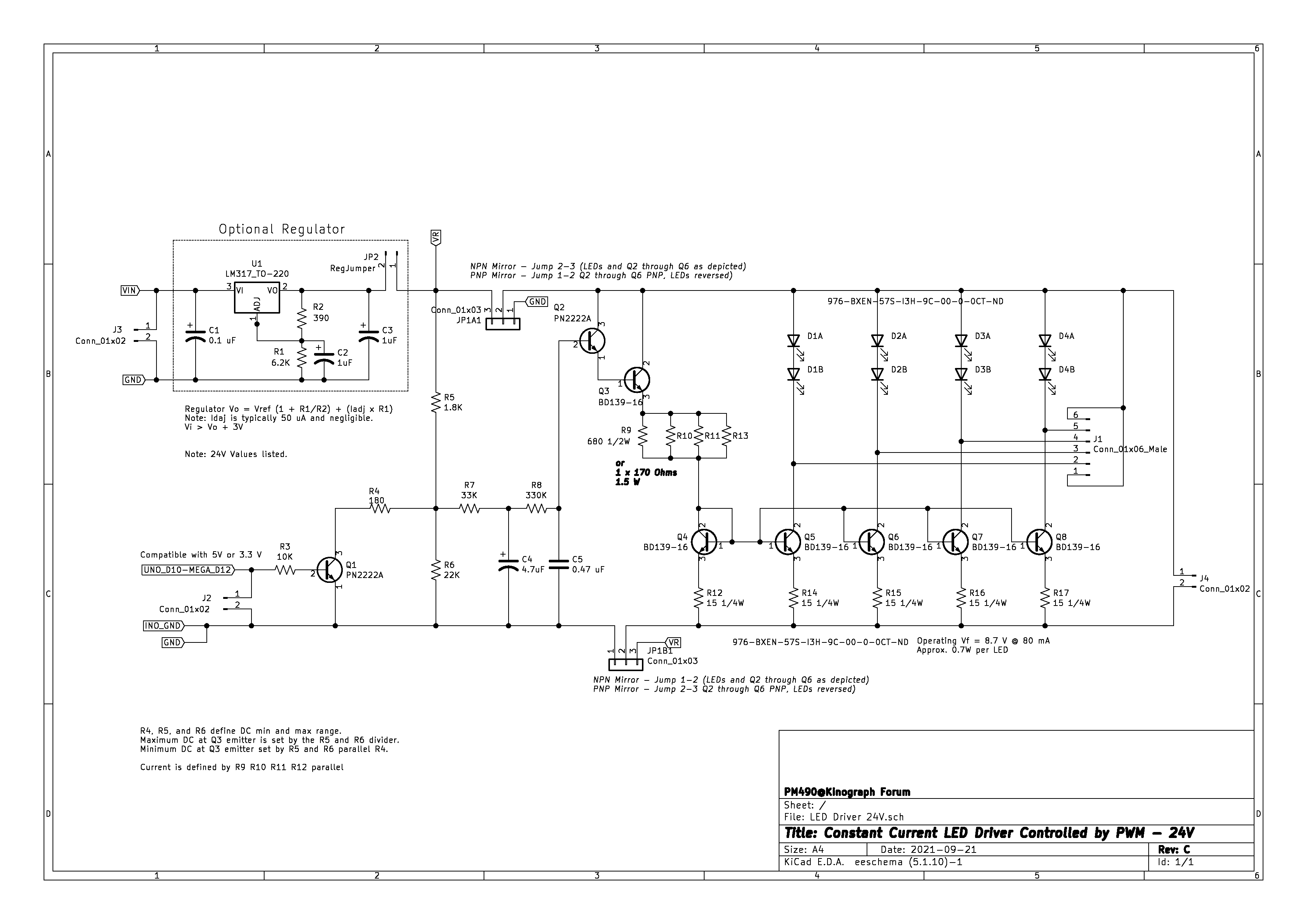
PS. Note that the schematics in the LED driver post are the early components (Through-hole easy to breadboard), which were revised/improved on the SMD board.
PS2. Like the design in your profile picture. Have been sketching a new sphere to accommodate more space for the color LEDs
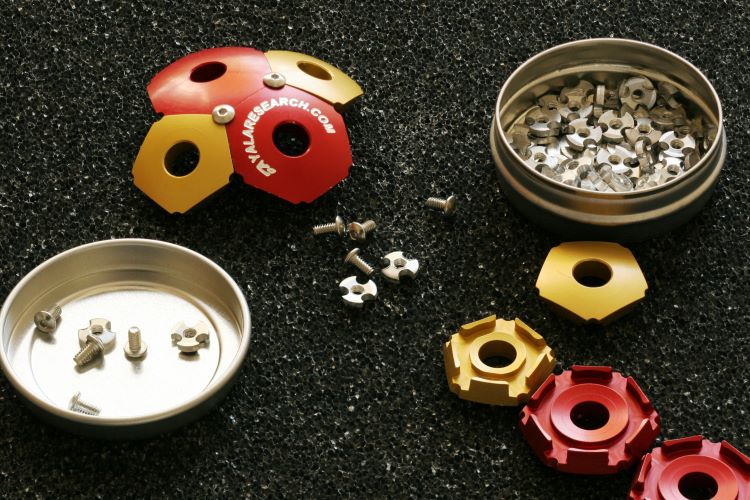
Thank you, you mean this:

It was designed in SolidWorks and we machined about 100 of these, that’s about 1,200 pentagons, 2,000 hexagons, 12,800 special washers (we made in house too) and 12,800 2-56 UNC button head screws.
We made kits to assemble these and gave them as thank you gifts to our best clients.
So in response to your mentioning the laser cut plate, I am considering that or water jet cutting an aluminum plate, probably 3/8" or 10 mm thick. On the TScann concept, as you say it’s mature, and it reminds me of big reel to reel tape decks from the 70’s. So there is an aesthetic to it.
I am redesigning the film gate and will machine that from aluminum and have it hard anodized, perhaps teflon impregnated, it is hard, smooth an lubricous. I suspect much of the jumping you see frame to frame in the TScann design is due to imprecise components. It works, don’t get me wrong, and if you don’t have the ability to do precision machining, 3D printing provides a reasonable alternative.
Thank you for the recommendation on the caps for the TMC2209’s. The A4998’s have a different pin assignment from the TMC2209s. They are old school and not so smooth. One benefit we have on this project is that 3D filament printers have brought down the cost of many of the components we need, stepper motors, bearings, stepper electronics, etc.
1 Like
I too am considering S8, 8 and 16 mm, though all my archive footage is 8 or S8, give the effort involved.
I am equivocal on contact / not contact particularly at the film gate. As far as I’ve seen a number of “professional grade” machines contact the film on the non emulsion side and not in the image area. The advantage of running with slight tension against a fixed surface is it is very much stable, no bearing or roller run out. Unless one was running the film over and over and over again, it think the additional wear is minimal. Considering how many of these films have been run through old cameras and projectors. Also consider that as you wind the film from one real to the next, there is almost certainly rubbing between the emulsion side against the non-emulsion side.
I’ll start posting things as I make progress. Like yourself, many other commitments get in the way…
2 Likes
I can’t recall if I answered the A4988 vs TMC2209 question, there is a difference in the pinouts, at least for the versoins I have looked at, version the TScann PCB. In the version of board I am working on, given that I am likely starting with Alt-Scan software, which is compatible with the TScann PCB, I will have jumpers to set the MS1 and MS2 pins.
Looking at the Tscann8 schematic, and the A4988 Datasheet Page 6, the microstepping is set as follows:
Step A and Step C: MS1 High, MS2 High, MS3 Low = Eighth Step
Step B: MS1 MS2 MS3 High = Sixteenth Step
Pinout differences of the carriers, for reference using Pololu Schematic and Bigtreetech TMC2209 V1.2
The differences:
     |AA4988 | TMC2209
-----+-------+-------------------
Pin4 |  MS3  | Jumper to PDN_UART
Pin5 |  RST  | Jumper to PDN_UART
Pin6 |  SLP  | CLK
On the TScann8 PCB, Pin 6 and Pin 5 are connected together. Pin 4 is open in Step-A and Step C, and connected to 5V on Step-B.
That looks workable… I think.
From the TMC2209 datasheet
Page 8, CLK input is for an optional external clock, if not provided it has timeout detection and reverts to internal clock. So no issue with pin 6 connected to pin 5 on the Tscann8 board, since it goes to a jumper on the TMC2209 carrier. Pin 4 also to another jumper on the TMC2209 carrier.
Page 14 the MS1 and MS2 configuration. If both are high -as wired in the PCB- it will be operating in 16 microsteps, which is correct for Step-B.
Step-A and Step-C are for controlling the reels… Took a quick look at the code, and looks like the step pins are MotorA_Stepper and MotorC_Stepper.
Can the step be doubled in code?
In other words, when the A4988 code makes one step by going high/low, just do it twice = two steps for the TMC2209 code.
Unless I am missing something, looks like you can drop in a replacement carrier with a TMC2209 (look for the ones that have PDN_UART the jumper open), change a few lines of codes to double the steps for A and C, and it should work.
The above is not to say that you can make a much nicer PCB with the TMC2209s (including the proper noise control capacitors)… but looks like a lot of work to end up with an Arduino Nano… just thinking out loud.
Maybe change the Nano to Pico?
As soon as I noticed the differences, I decided I would start a new layout. There were other ones too, the use of a resistor to current limit the white LED, and I sourced a surface mount UV LED and phototransistor.
I think the pico is probably more capable, but I didn’t want to add the additional layer of having to modify the code. I did a very preliminary test with the uv led and phototransistor, and I get a good signal as it goes past the sprockets.
Pololu has lots of options for stepper drivers, I don’t know how the TMC2209 would compare to some of their other offerings, but the silent step quite obviously works.
1 Like