Raspberry HQ - capturing or extracting raw values

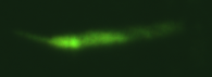
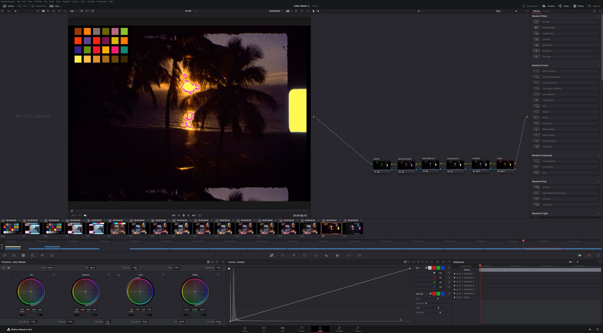
@verlakasalt asked for additional information on the methods I have been used to extract raw values on experiments in these postings.

The setup is a Raspberry Pi 4, and the Raspberry HQ sensor/camera, python.

Keeping it fast
The RPi4 is underpowered for the task. Even worst if one is using the Pi via VNC, and have a GUI with a waveform monitor.
Sharing every detail on how/why this even runs in a RPi4 will make the post too dense in hard core python libraries. At this time, I am going to share the highlevel items that make this possible, so everyone can take advantage of new tools in their own setup.

  • Keep the camera running. The camera never stops, and the configuration does not change.
  • Core Association. Used the multiprocessing library to associate time consuming tasks to a specific core. The capture loop to one, the debayering to another.
  • Shared Memory. Core association + alternating buffers of shared memory allow concurrent capturing, debayering, and saving.
  • Numpy and Numba. This is a powerful combination, Numba is an open source compiler that translates a subset of NumPy into fast machine code. The improvements are an order of magnitude faster, and it serves well the tasks of debayering, sprocket detection, and waveform monitor processing.
  • Picamera2 Configuration oddities. Different modes take different processing time, using preview configuration vs still configuration would shave tens of milliseconds of the capture.
  • Tradeoff of Resolution vs Pixel Depth. Instead of debayering to the full resolution of the sensor, which is processing intensive, I made the choice to bin the RGGB. The result has half the resolution (2032x1520) of the raw capture (4064x3040). This tradeoff however, increases the bit depth of the Green, since to hold G1 + G2 (each of 12 bit depth) is necessary to have 13 bits. This very item can be the subject of much discussion, I have been always in favor of more pixels, but the increased bit depth in green, and making each pixel true (not interpolated) provides -for me- a worthy trade off.

Common Code to both Alternatives
The camera setup is common regardless if you are saving the raw array or saving a DNG. It is important to highlight that the explicit sensor format will also determine the debayering order. If a format other than SRBBG12 is used, the debayering lines will change.

# Code Extract
        self.pihqcam = Picamera2(tuning=tune)
        self.cam_controls = {
            "AwbEnable": False,
            "AeEnable": False,
            "FrameRate": 10,
            "AnalogueGain": 1.0,
            "Sharpness": 0.5,
            "Saturation":1.0,
            "ColourGains": (1.0, 1.0),# (R,B) Has no effect the raw array, affects DNG development
            "ExposureTime": 20000,
            "NoiseReductionMode": controls.draft.NoiseReductionModeEnum.Off,
            "FrameDurationLimits": (100, 100000)
        }
# Code Extract
            self.pihqcam.create_preview_configuration(queue=False)
            self.pihqcam.preview_configuration.main.size = global_shape_main #this should be 4056, 3040
            self.pihqcam.preview_configuration.main.format = "RGB888"
            self.pihqcam.preview_configuration.transform=Transform(hflip=True) # Camera rotated 90 degrees capturing from emulsion side
            self.pihqcam.preview_configuration.raw.size = global_shape_sensor
            self.pihqcam.preview_configuration.raw.format = "SRGGB12"     # Sets Debayering order
            self.pihqcam.configure("preview")

ALTERNATIVE 1 - Capture a raw array and save as image

The line used to capture the raw values is:

                self.raw_frame_16[:]= (self.pihqcam.capture_array("raw").view(np.uint16))#12BIT

raw_frame_16 is an 16 bit unsigned integer numpy array (3040,4064) (height, width). The result of the capture_array method is 12 bits per channel packed, the addition of .view unpacks these into 16 bit pixels. The values will correspond to the 12 least significant bits.

The method used to debayer and bin (including the use of numba) is as follows:

from numba import njit

    @staticmethod
    @njit
    def debayer_rgb16(raw_frame,rgb_frame):
        height,width = raw_frame.shape

        green_channel_1 = raw_frame[0:height:2, 0:width:2]          # Top-left green
        blue_channel    = raw_frame[0:height:2, 1:width:2]          # Top-right blue
        green_channel_2 = raw_frame[1:height:2, 1:width:2]          # Bottom-right green
        red_channel     = raw_frame[1:height:2, 0:width:2]          # Bottom-left red

        rgb_frame[:,:,2] = blue_channel << 4                        #Shifted to the 12 MSBits
        rgb_frame[:,:,0] = red_channel << 4                         #Shifted to the 12 MSBits
        rgb_frame[:,:,1] = (green_channel_1 + green_channel_2) << 3   #Shifted to the 13 MSBits

Note that when using numba, the self argument is omitted on the declaration. If numba is not used, remove the @ lines, and include a self as the first argument.
rgb_frame is expected as a numpy array (1520,2032,3) (height, width, channels)

Lastly, the line to save as an unsigned 16bit tiff (same numpy array dimensions as above).

# Code Extract
  tifffile.imwrite(save_name, self.rgb_frame_16, compression=None)

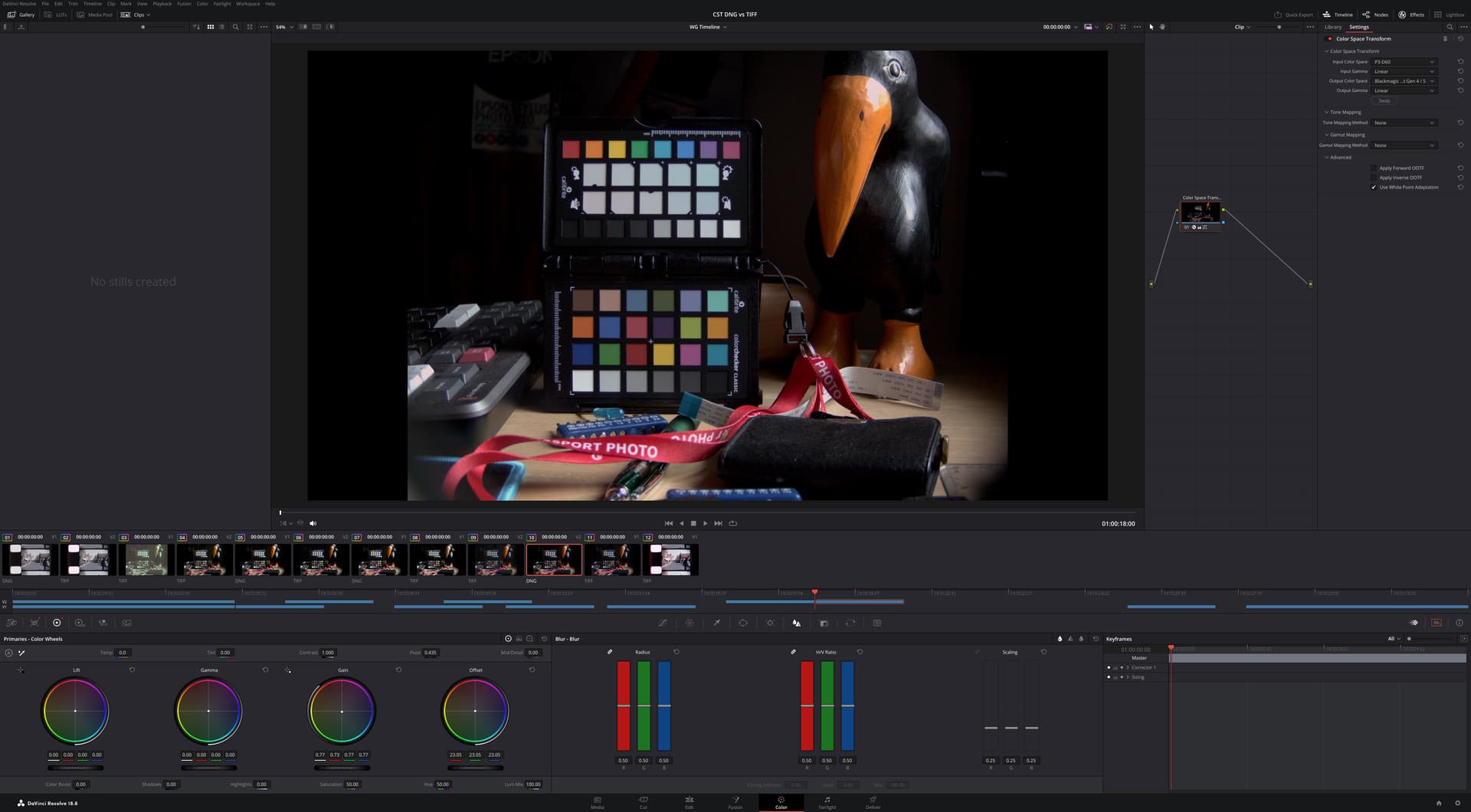
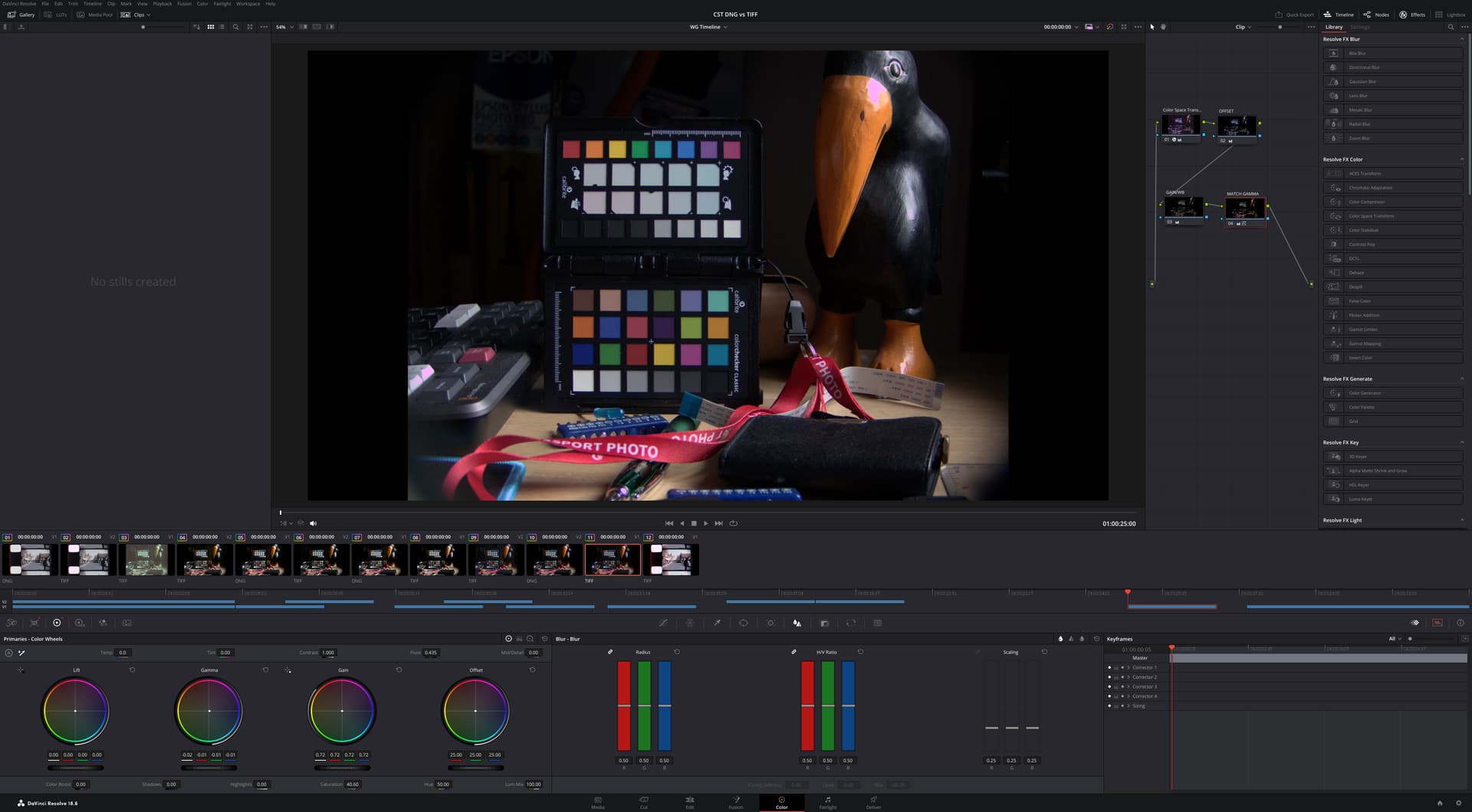
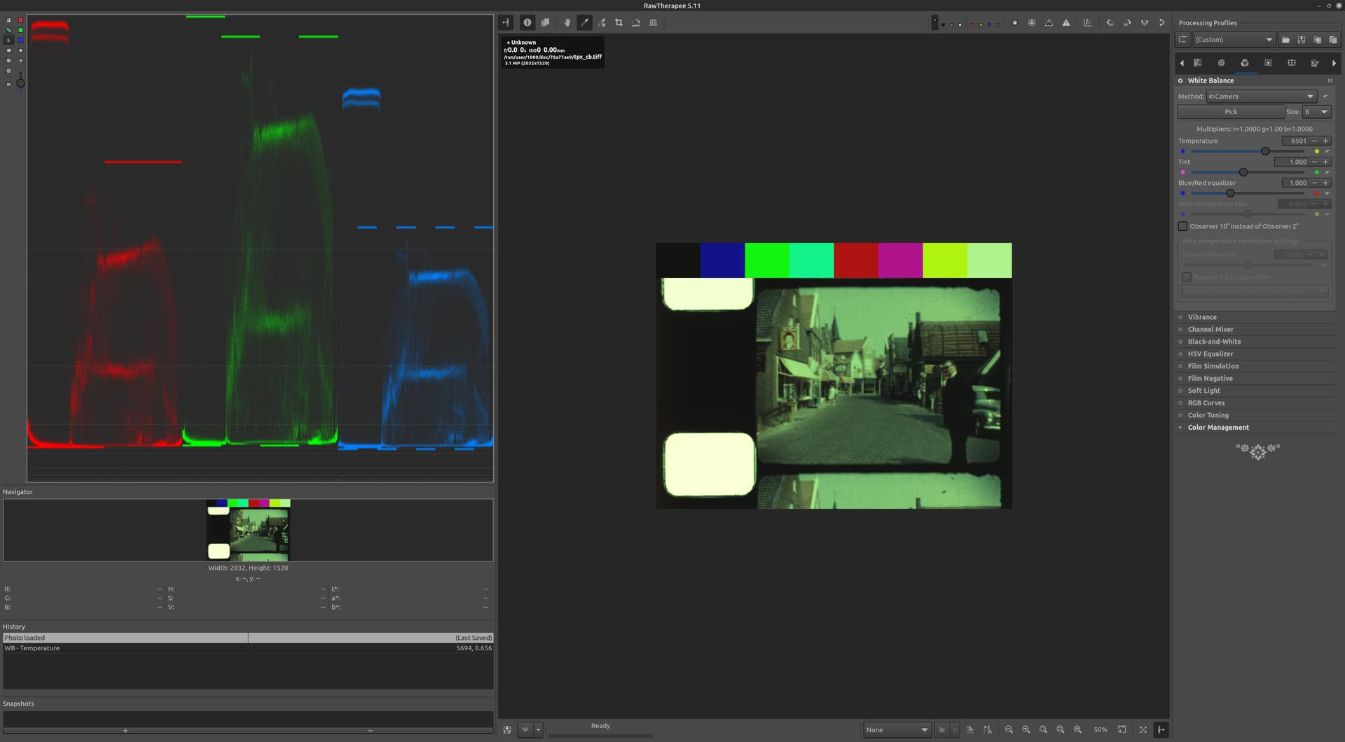
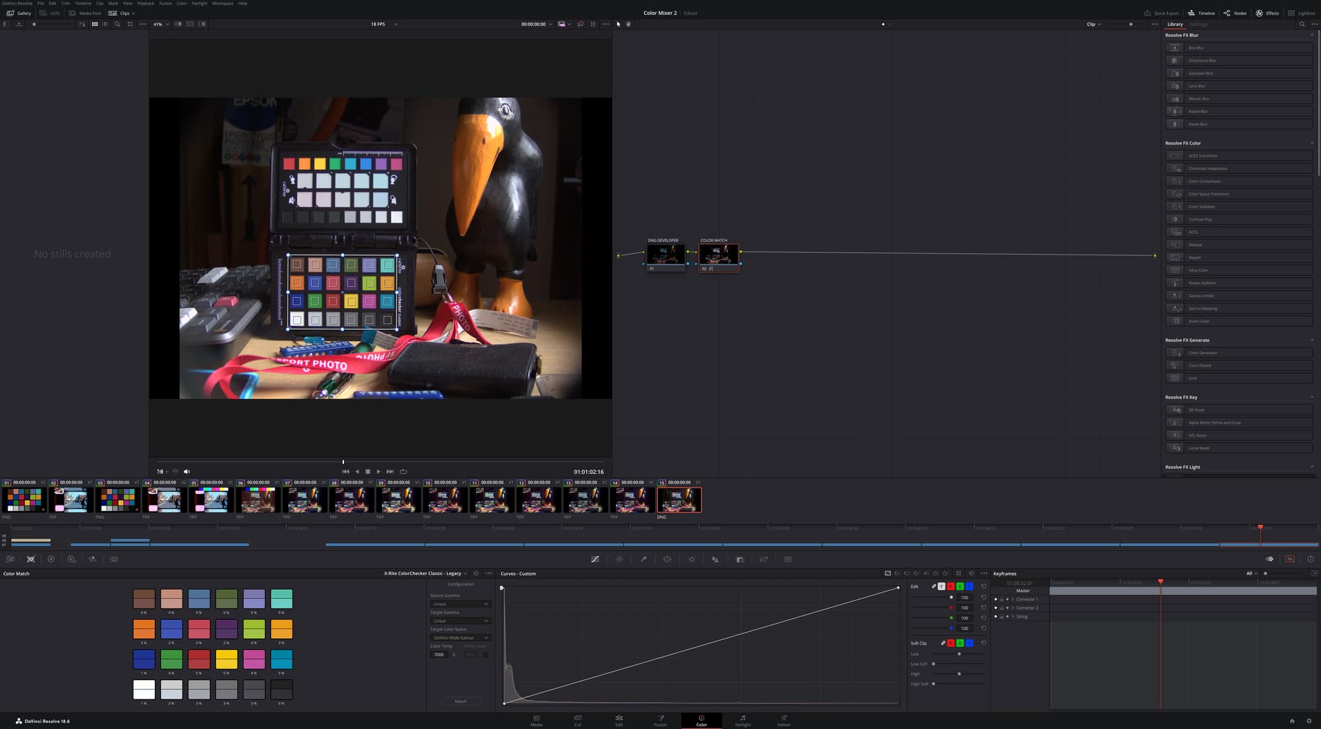
ALTERNATIVE 2 - Save a DNG and extract raw values
This alternative is to save a DNG file, in whichever way is best for your particular situation, and then extract the same raw value image.

The original code below was shared by @cpixip, remixed to add the debayering of the SRGGB12 sensor format pattern.

import numpy as np

import rawpy
import tifffile

path = r'tpx_L0800_church.dng'

inputFile = input("Set raw file to analyse ['%s'] > "%path)
inputFile = inputFile or path
outputFile = inputFile+".tiff"    
# opening the raw image file
rawfile = rawpy.imread(inputFile)    
print ('Rawfile Pattern',rawfile.raw_pattern[0][0])
print ('Rawfile shape', rawfile.raw_image_visible.shape)

# get the raw bayer 
bayer_raw = rawfile.raw_image_visible
bayer_raw_16 = bayer_raw.astype(np.uint16)
rgb_frame = np.zeros(( 1520,2028,3),dtype=np.uint16)

# quick-and-dirty debayer
if rawfile.raw_pattern[0][0]==2:

    # this is for the HQ camera
    red    =  bayer_raw_16[1::2, 1::2]                                 # Red
    green1 =  bayer_raw_16[0::2, 1::2]                                 # Gr/Green1
    green2 =  bayer_raw_16[1::2, 0::2]                                 # Gb/Green2
    blue   =  bayer_raw_16[0::2, 0::2]                                 # Blue

elif rawfile.raw_pattern[0][0]==0:

    # ... and this one for the Canon 70D, IXUS 110 IS, Canon EOS 1100D, Nikon D850
    red    =  bayer_raw_16[0::2, 0::2]                                 # Red
    green1 =  bayer_raw_16[0::2, 1::2]                                 # Gr/Green1
    green2 =  bayer_raw_16[1::2, 0::2]                                 # Gb/Green2
    blue   =  bayer_raw_16[1::2, 1::2]                                 # Blue

elif rawfile.raw_pattern[0][0]==1:

    # ... and this one for the Sony
    red    =  bayer_raw_16[0::2, 1::2]                                 # red
    green1 =  bayer_raw_16[0::2, 0::2]                                 # Gr/Green1
    green2 =  bayer_raw_16[1::2, 1::2]                                 # Gb/Green2
    blue   =  bayer_raw_16[1::2, 0::2] 

elif rawfile.raw_pattern[0][0]==3: #HQ SRGGB12

    red    =  bayer_raw_16[1::2, 0::2]                                 # red
    green1 =  bayer_raw_16[0::2, 0::2]                                 # Gr/Green1
    green2 =  bayer_raw_16[1::2, 1::2]                                 # Gb/Green2
    blue   =  bayer_raw_16[0::2, 1::2] 

else: 
    print('Unknown filter array encountered!!')

rgb_frame[:,:,0] = red << 4
rgb_frame[:,:,1] = (green1+green2) << 3
rgb_frame[:,:,2] = blue << 4

tifffile.imwrite(outputFile, rgb_frame, compression=None)

# creating the raw RGB
#camera_raw_RGB = np.dstack( [red,(green1+green2)/2,blue] )
camera_raw_RGB = np.dstack( [red,(green1+green2),blue] )

# getting the black- and whitelevels
blacklevel   = np.average(rawfile.black_level_per_channel)
whitelevel   = float(rawfile.white_level)

# info
print()
print('Image: ',inputFile)
print()

print('Camera Levels')
print('_______________')
print('             Black Level   : ',blacklevel)
print('             White Level   : ',whitelevel)

print()
print('Full Frame Data')
print('_______________')
print('             Minimum red   : ',camera_raw_RGB[:,:,0].min())
print('             Maximum red   : ',camera_raw_RGB[:,:,0].max())
print()
print('             Minimum green : ',camera_raw_RGB[:,:,1].min())
print('             Maximum green : ',camera_raw_RGB[:,:,1].max())
print()
print('             Minimum blue  : ',camera_raw_RGB[:,:,2].min())
print('             Maximum blue  : ',camera_raw_RGB[:,:,2].max())

dy,dx,dz = camera_raw_RGB.shape

dx //=3
dy //=3

print()
print('Center Data')
print('_______________')
print('             Minimum red   : ',camera_raw_RGB[dy:2*dy,dx:2*dx,0].min())
print('             Maximum red   : ',camera_raw_RGB[dy:2*dy,dx:2*dx,0].max())
print()
print('             Minimum green : ',camera_raw_RGB[dy:2*dy,dx:2*dx,1].min())
print('             Maximum green : ',camera_raw_RGB[dy:2*dy,dx:2*dx,1].max())
print()
print('             Minimum blue  : ',camera_raw_RGB[dy:2*dy,dx:2*dx,2].min())
print('             Maximum blue  : ',camera_raw_RGB[dy:2*dy,dx:2*dx,2].max())

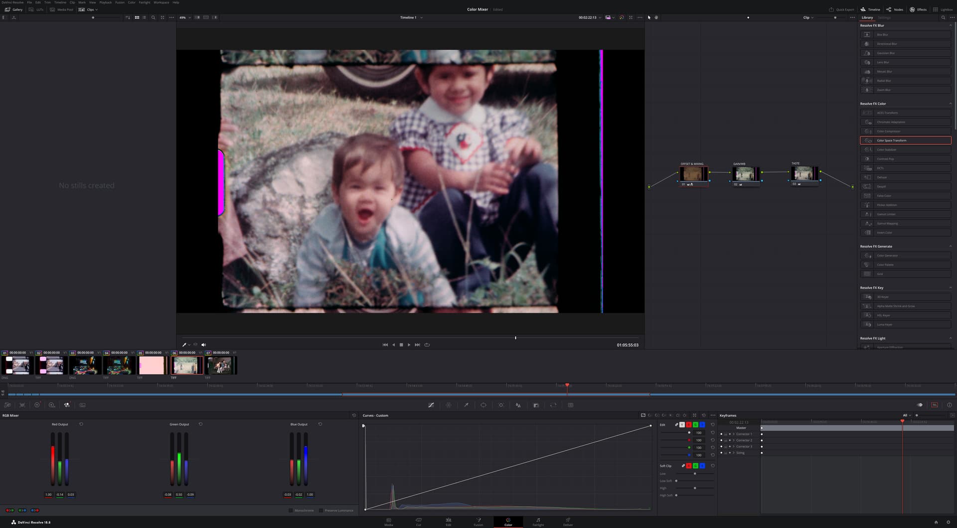
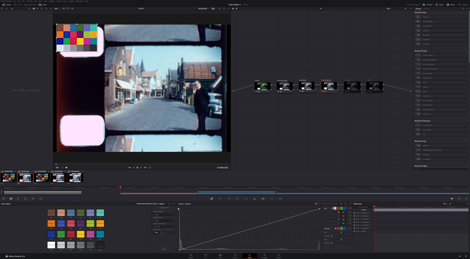
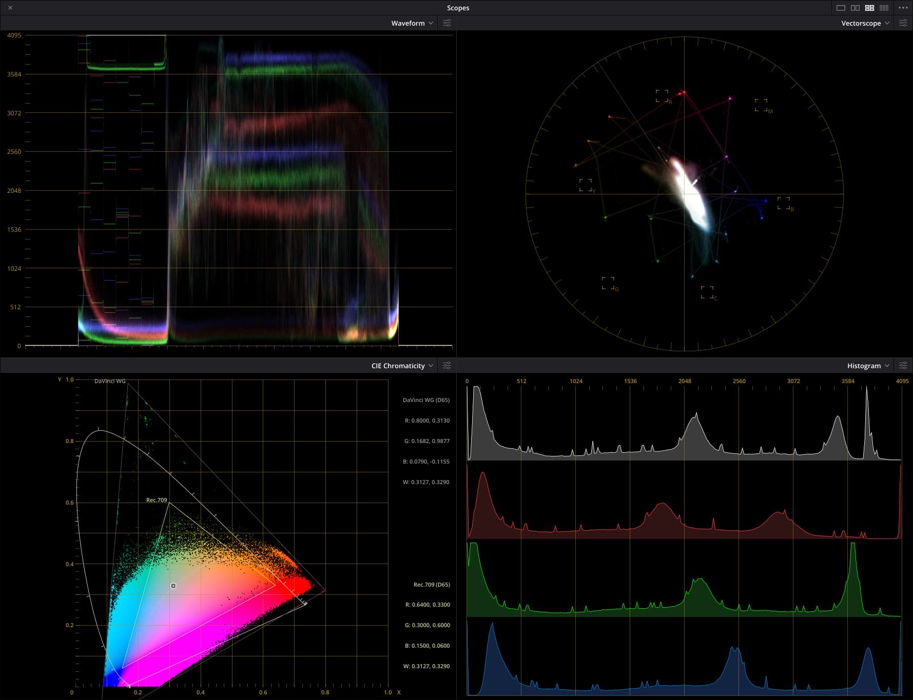
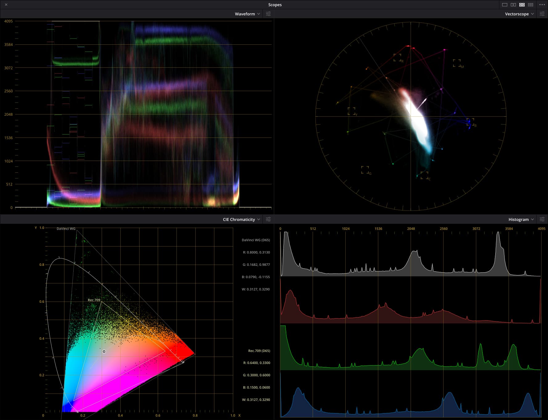
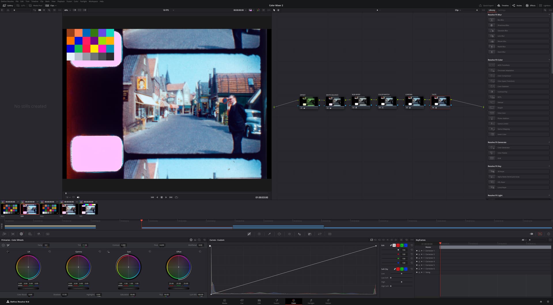
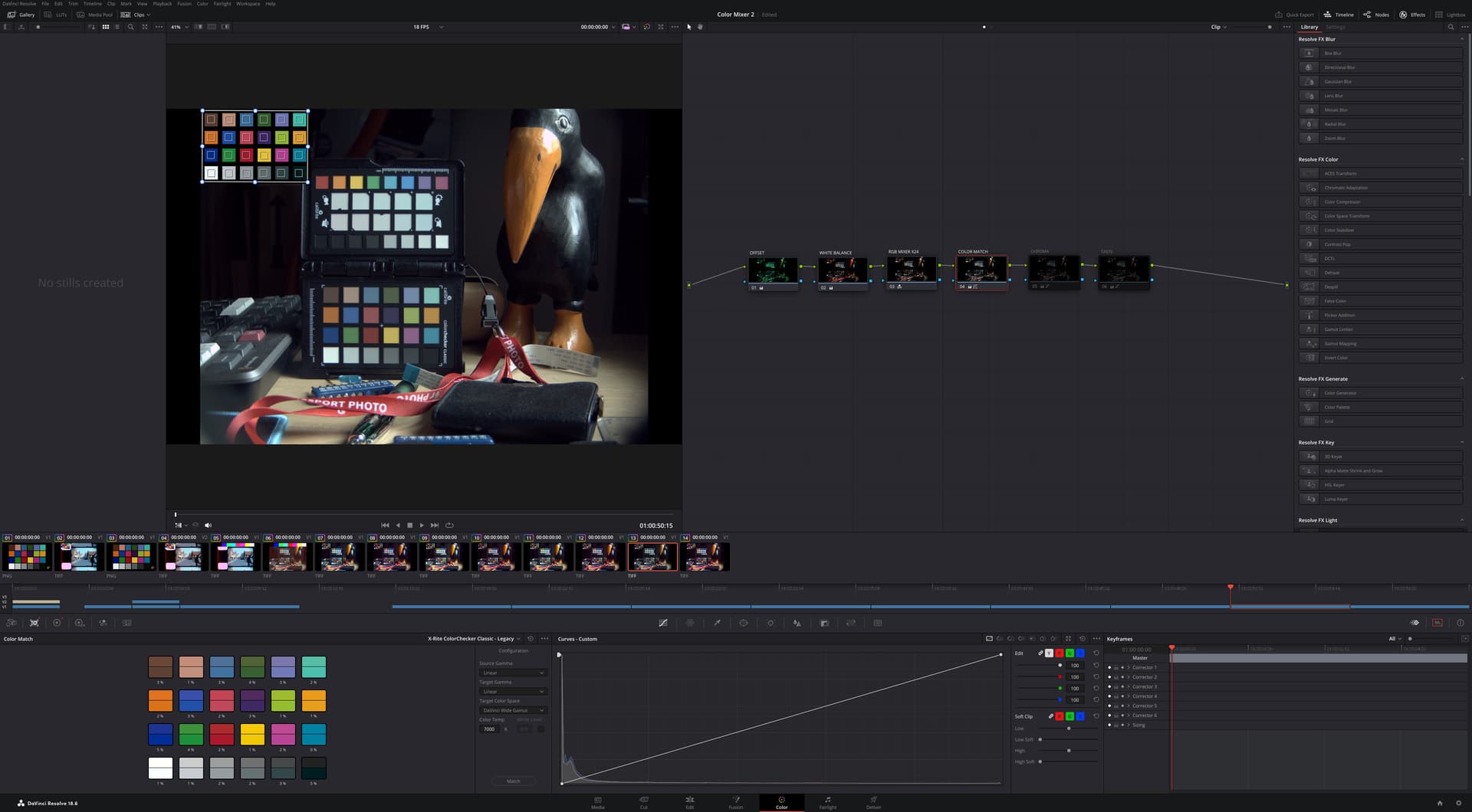
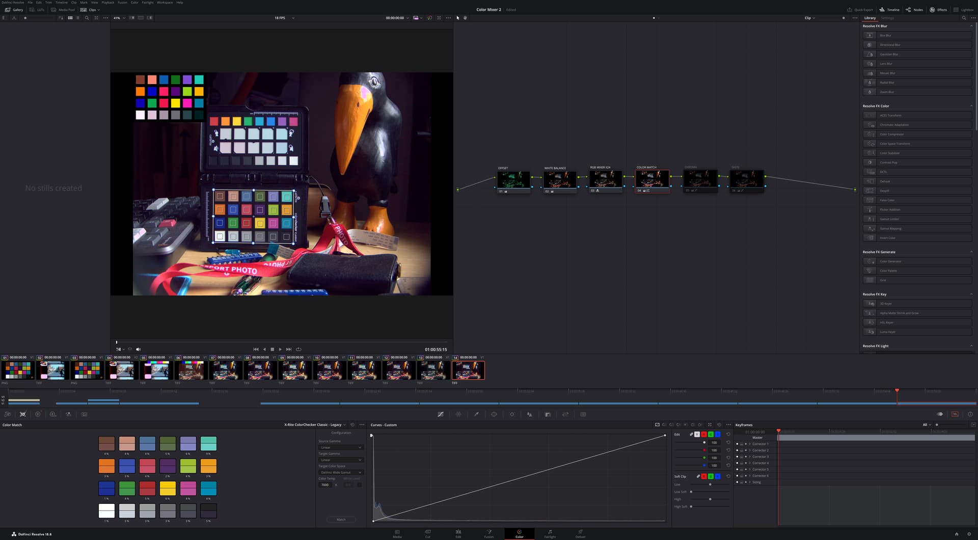
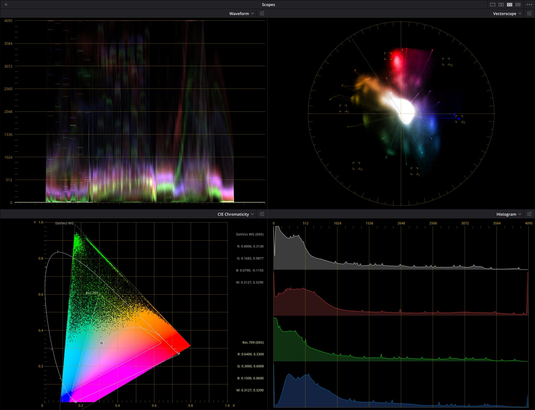
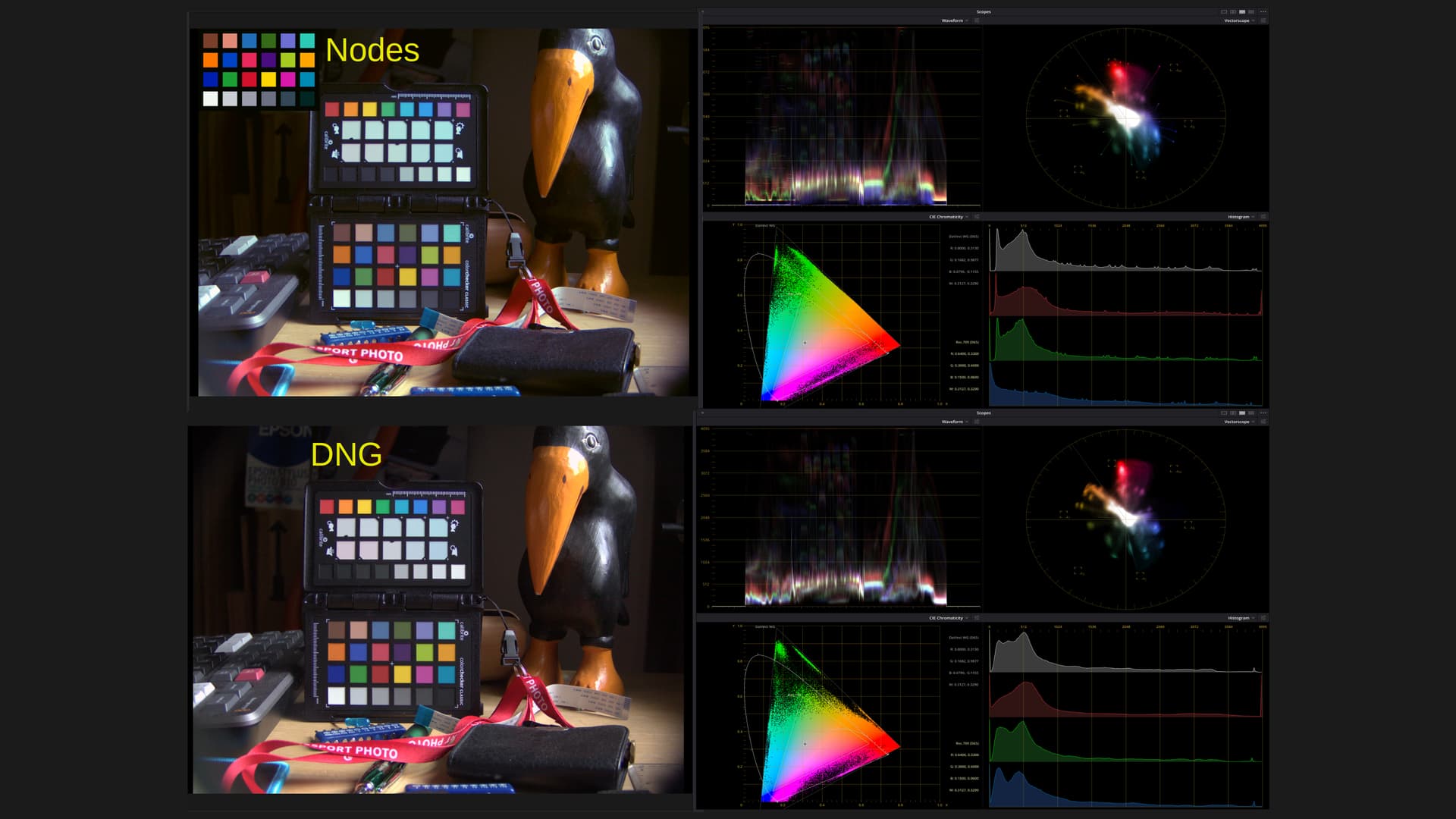
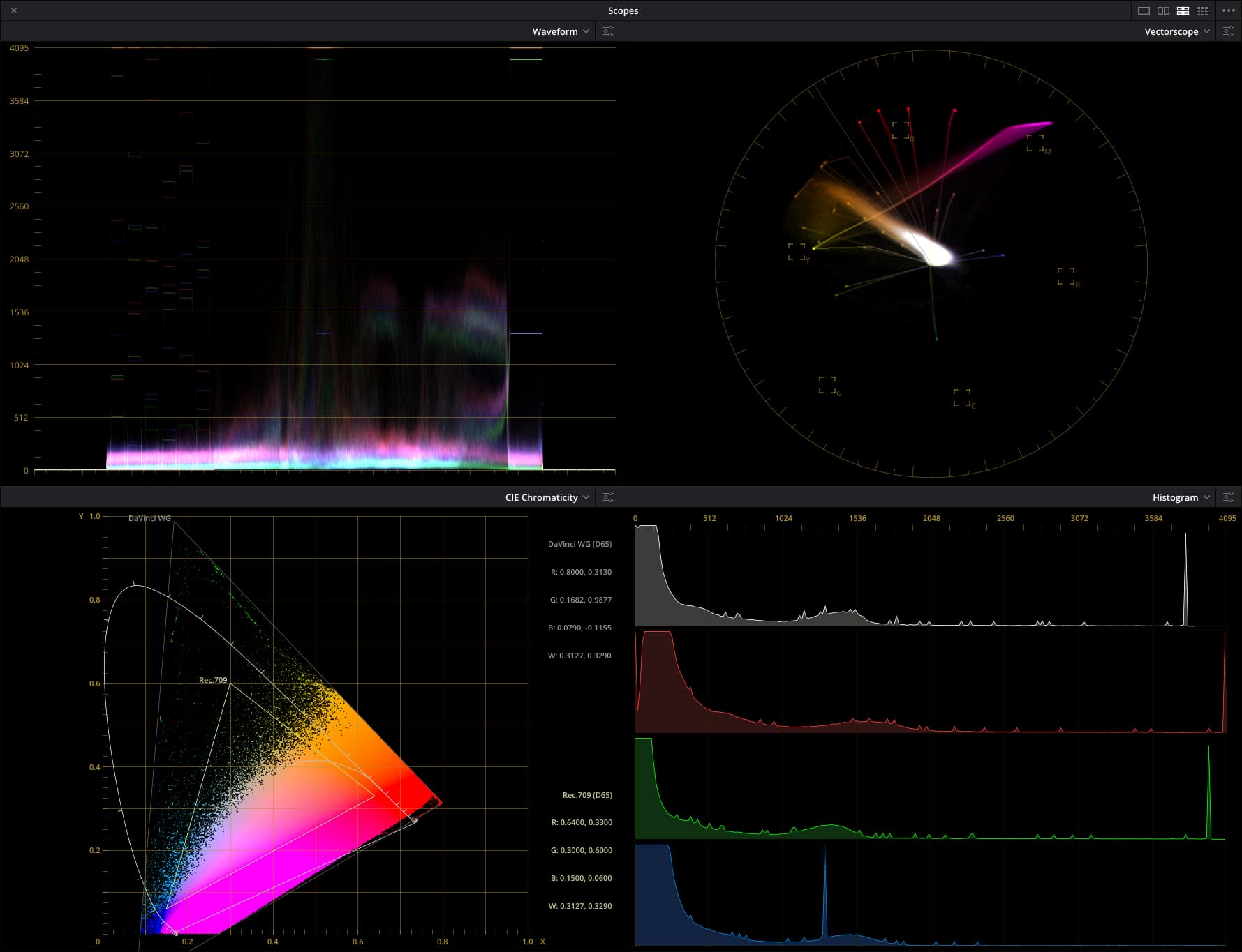
Understanding these alternatives
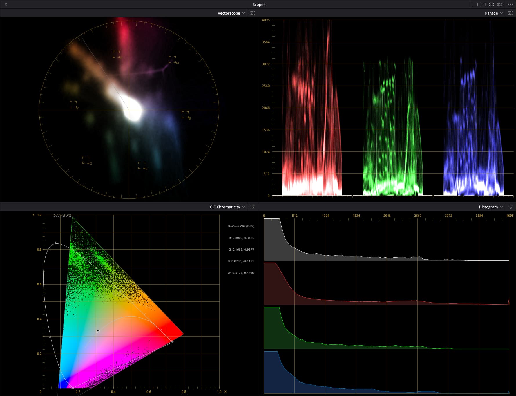
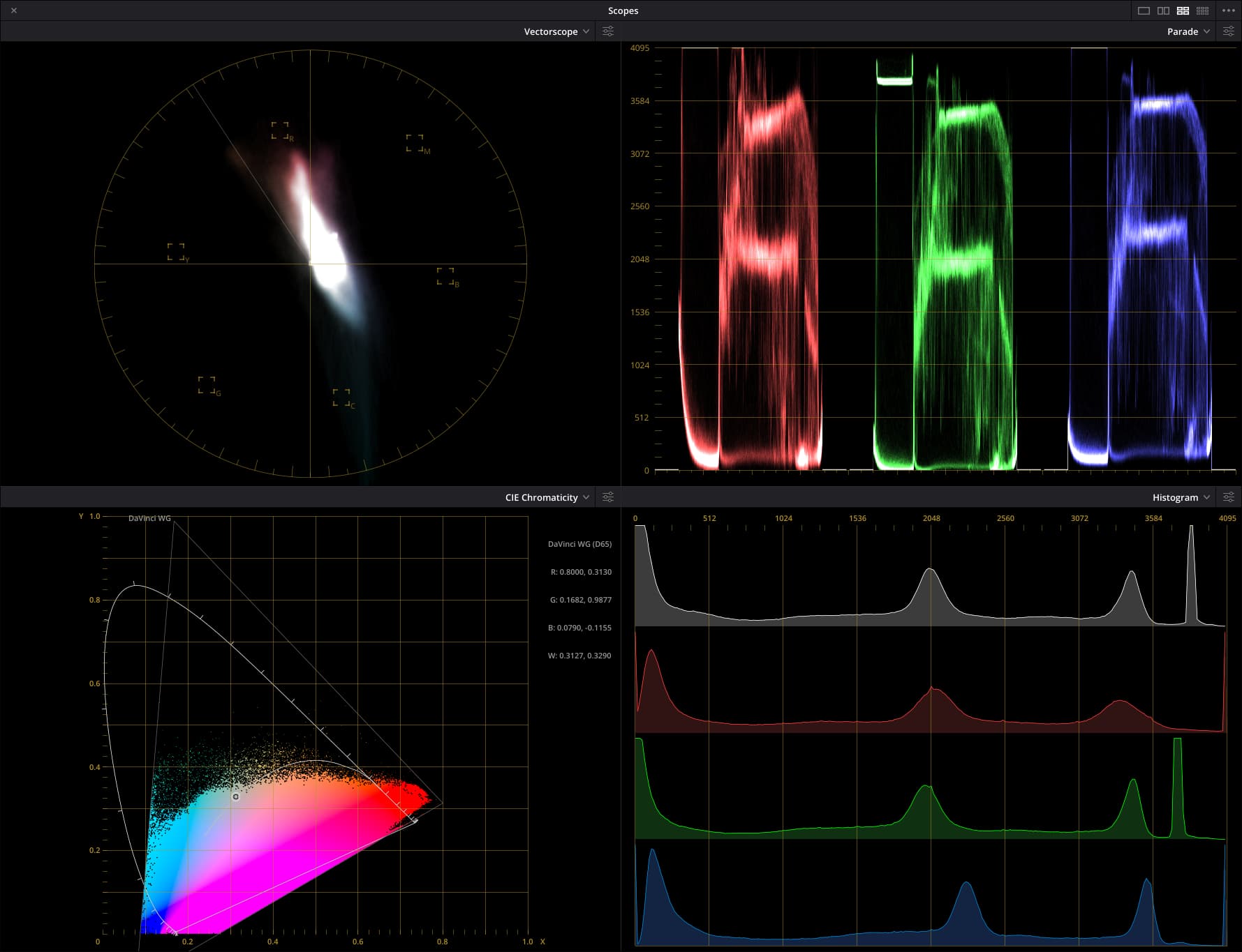
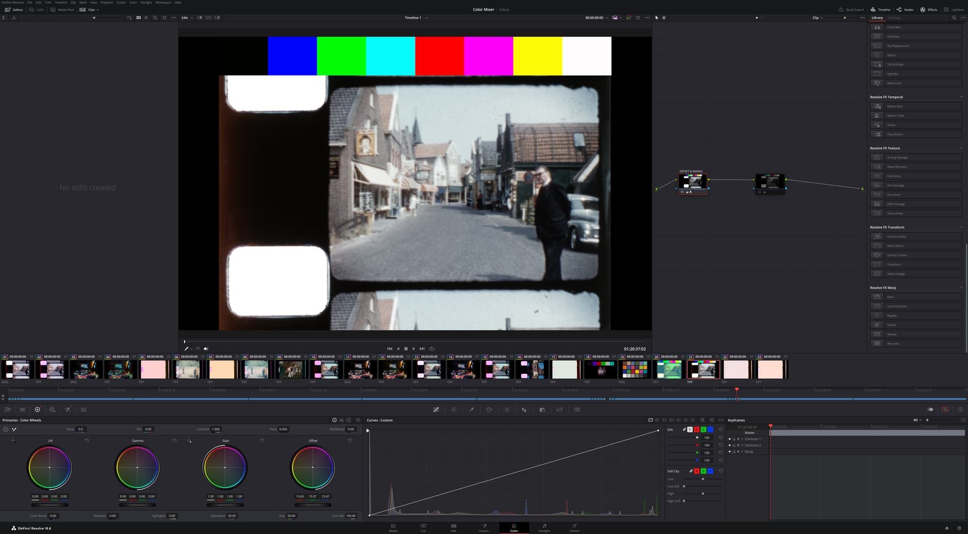
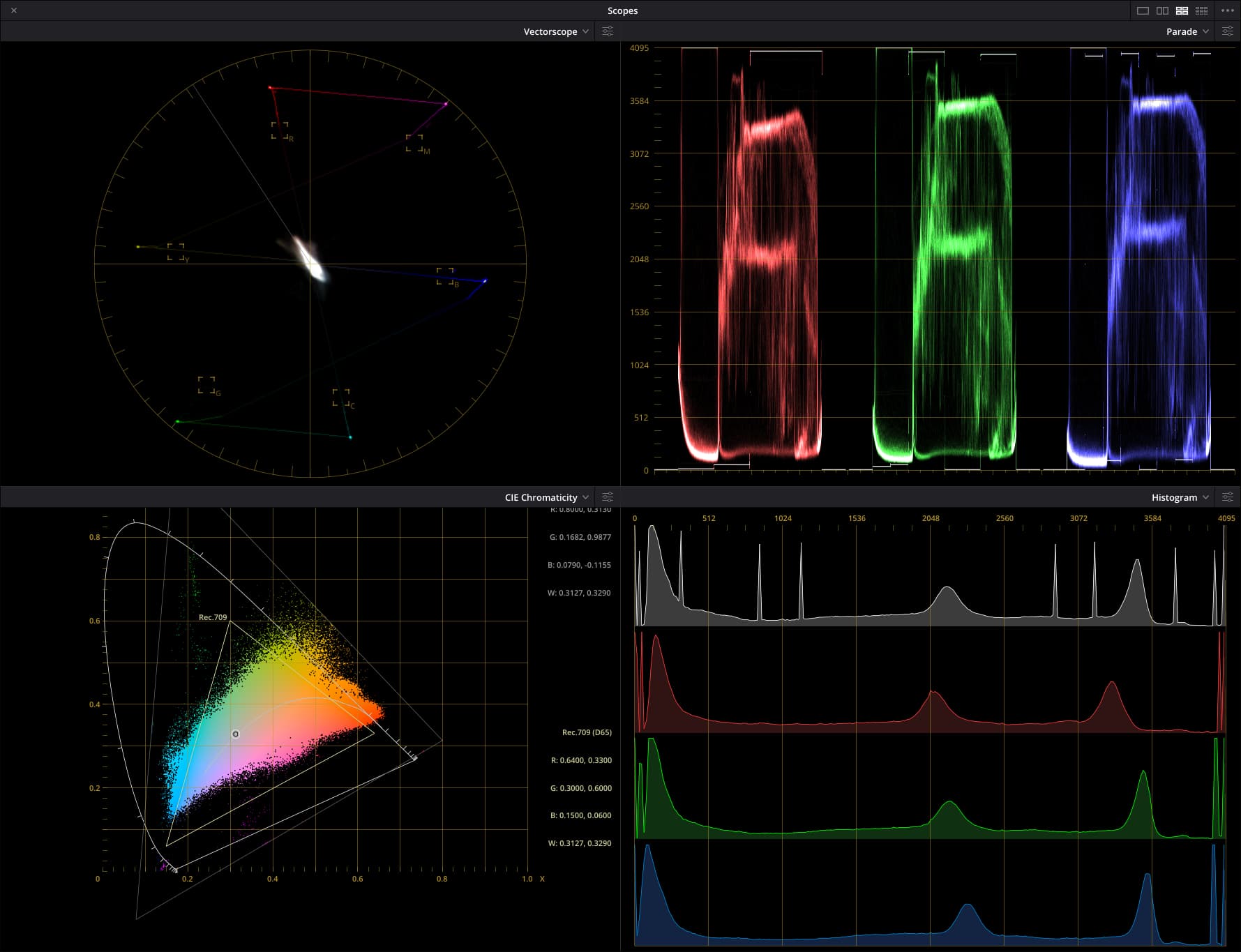
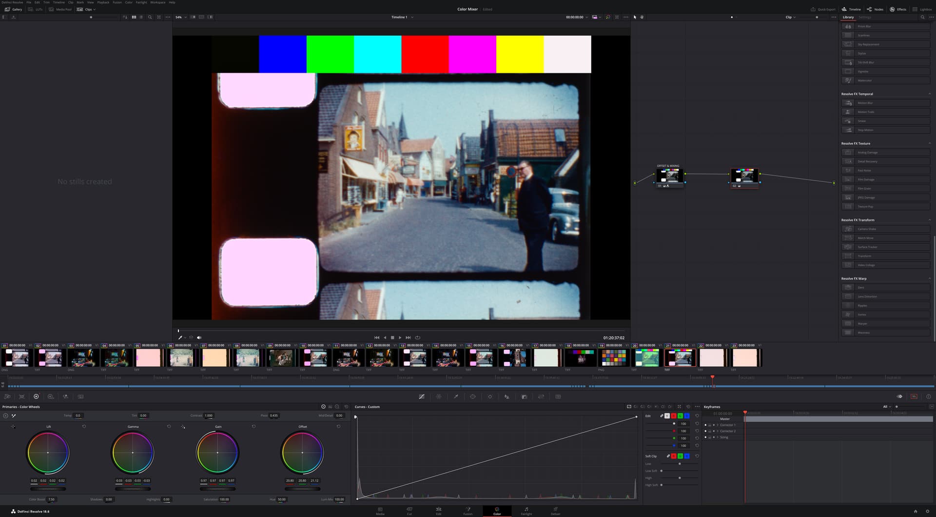
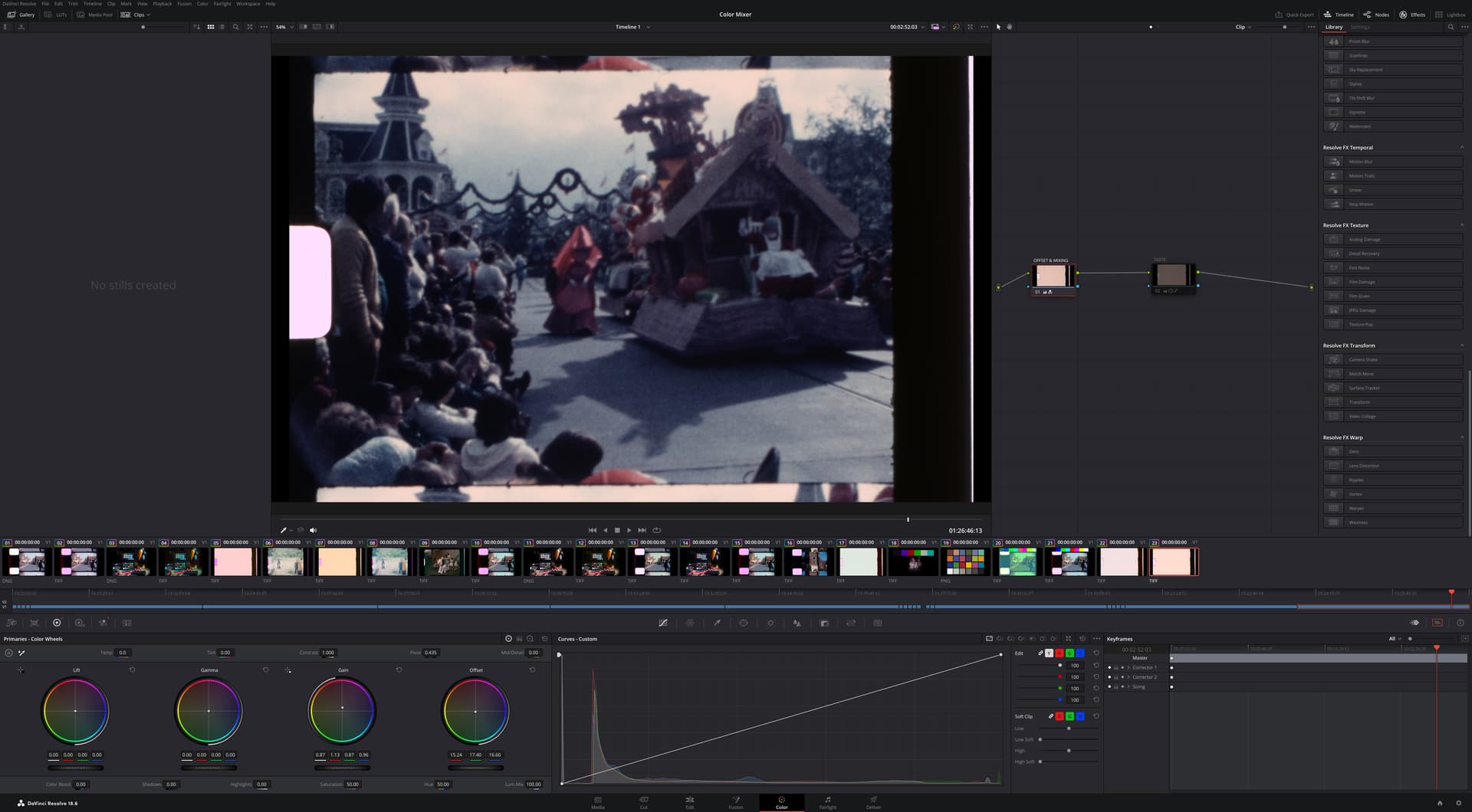
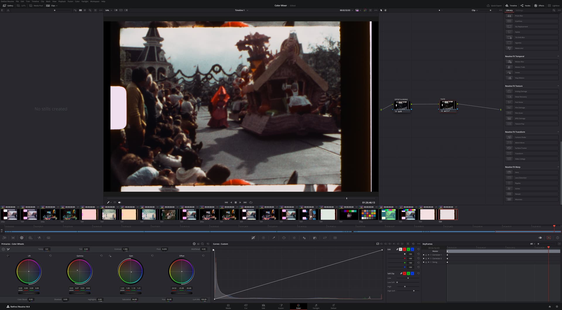
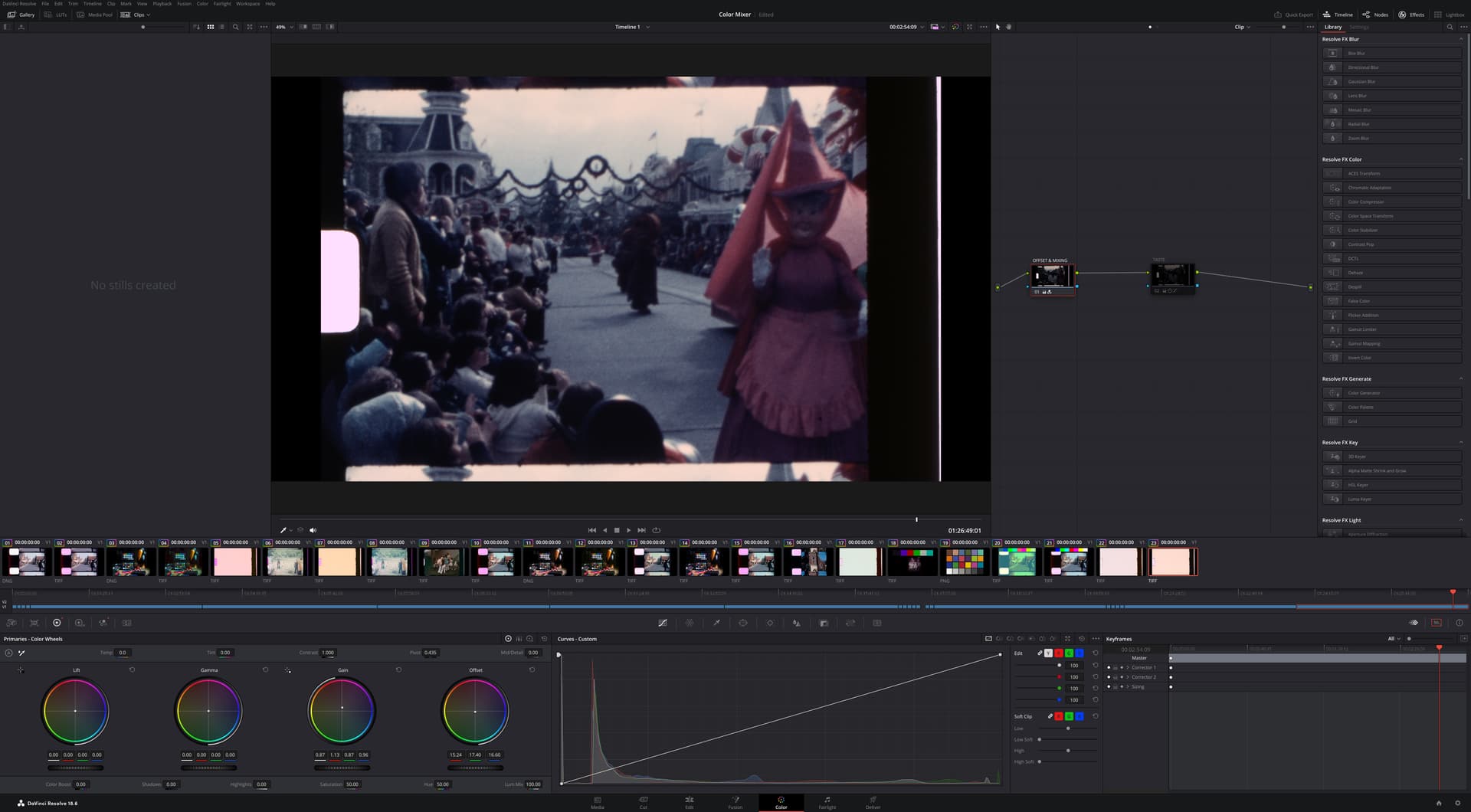
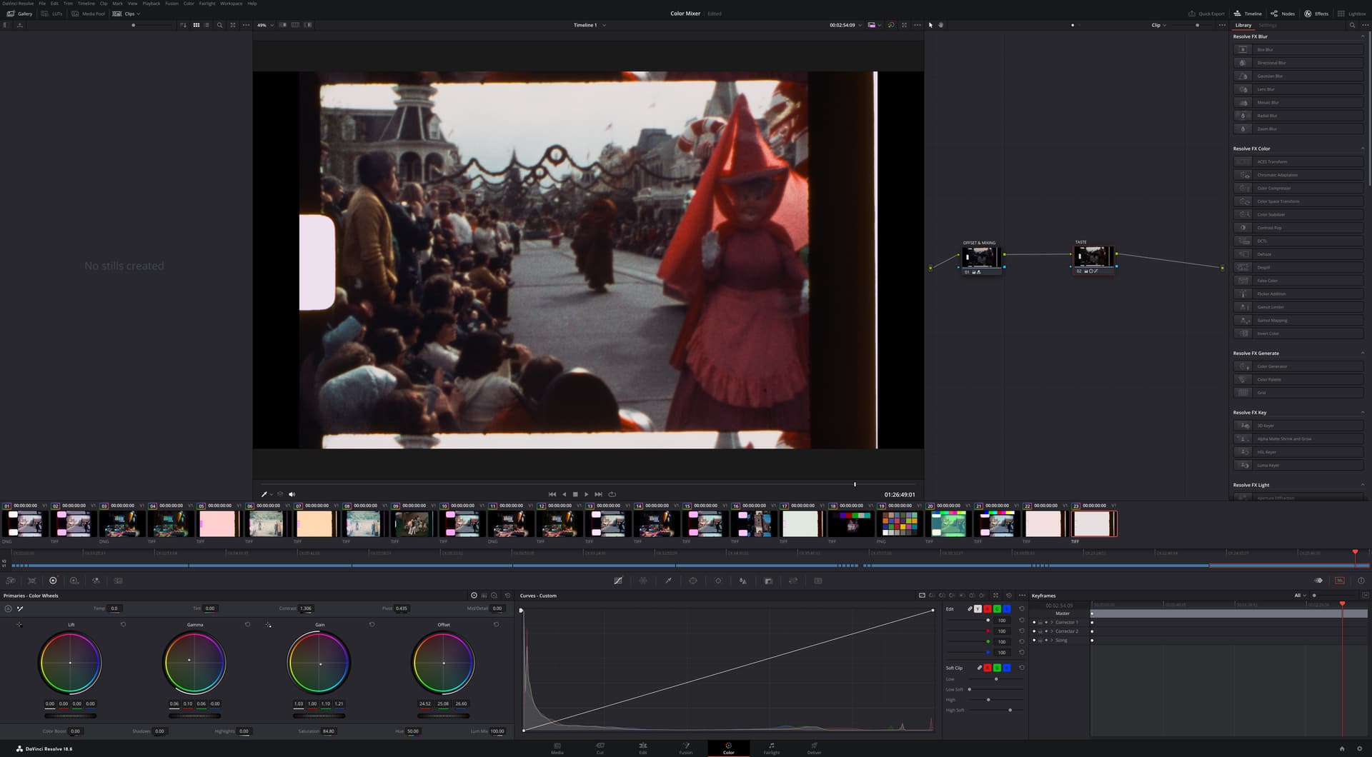
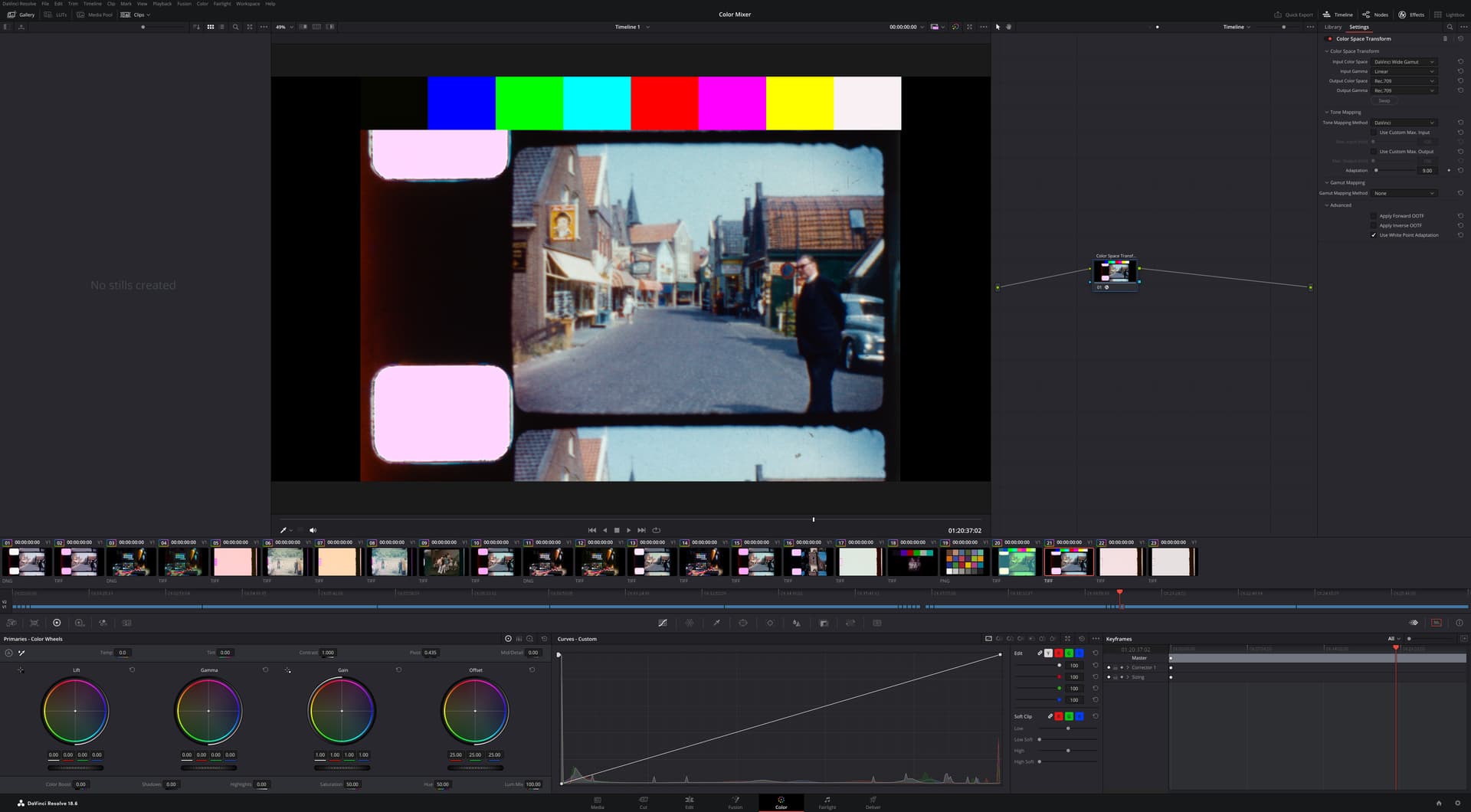
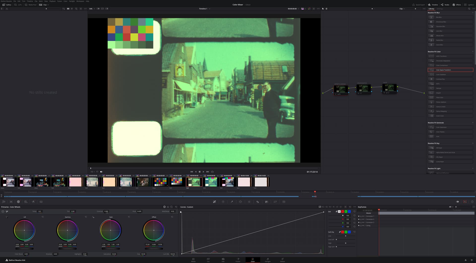
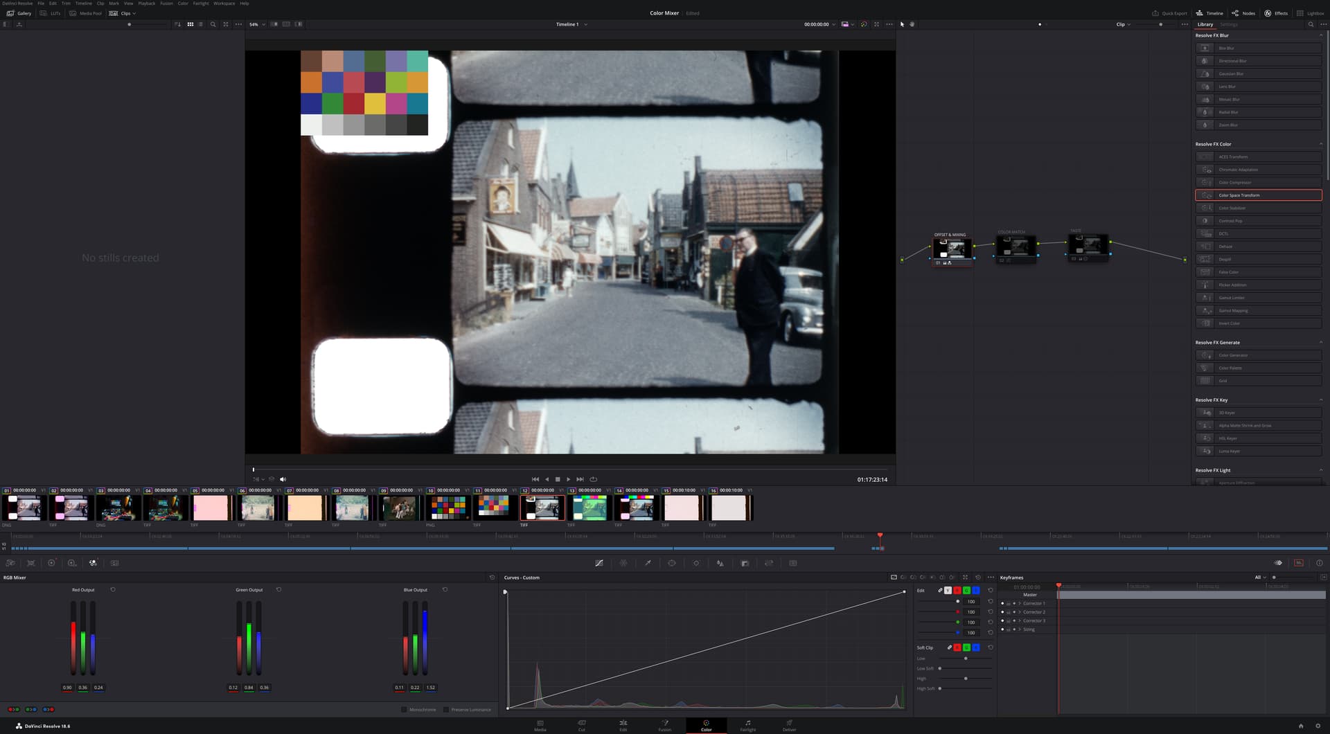
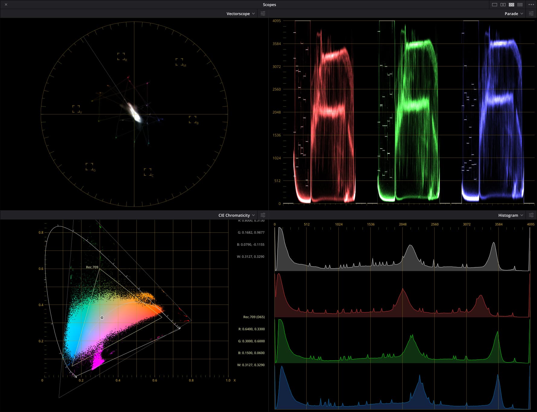
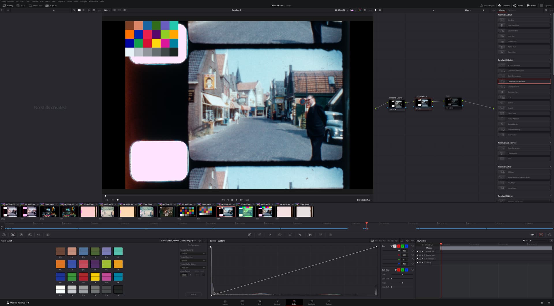
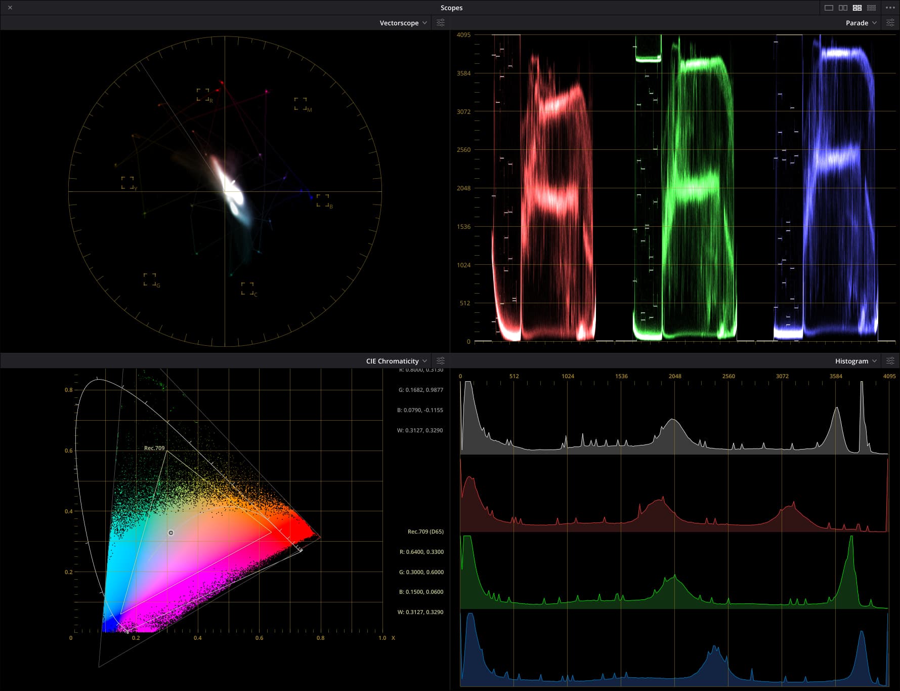
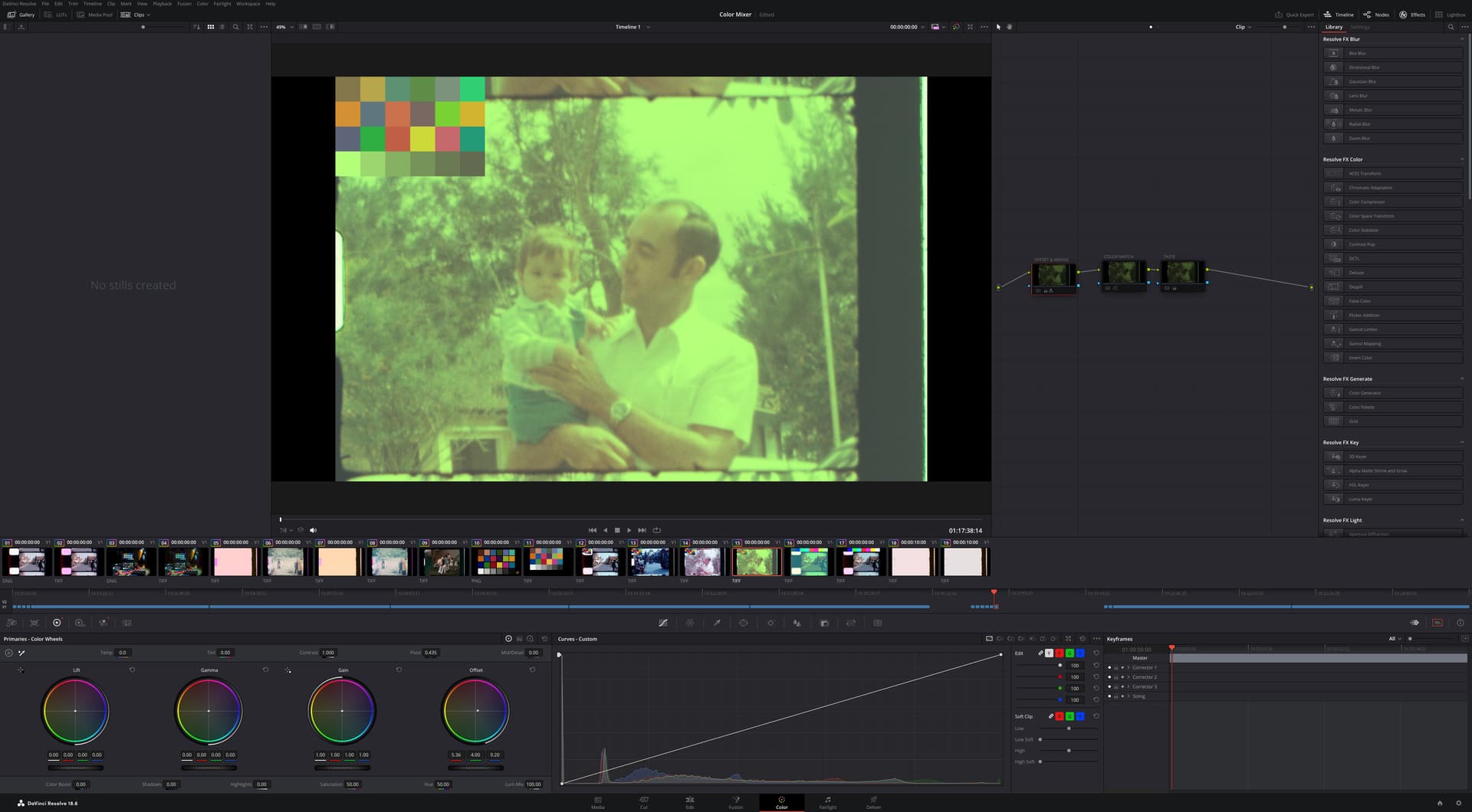
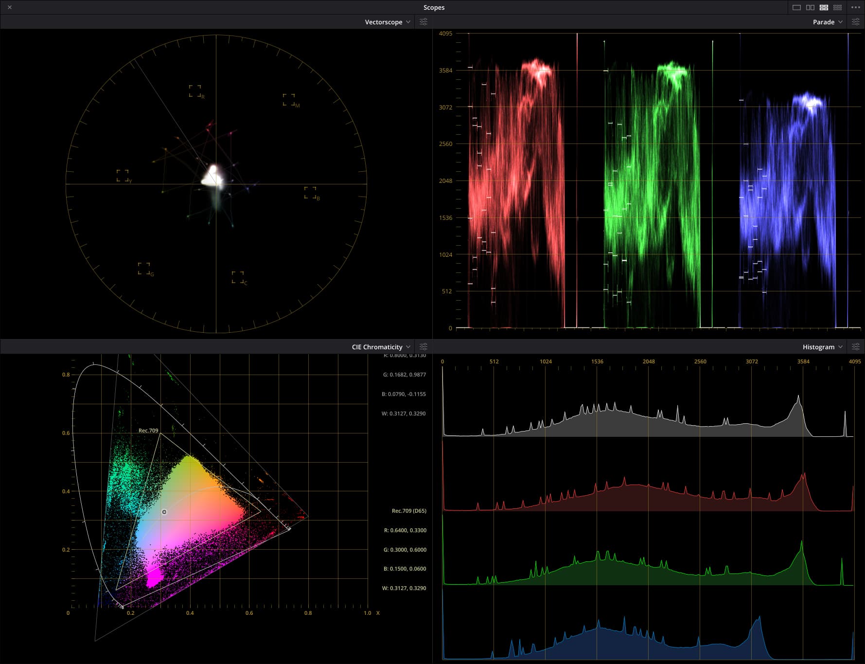
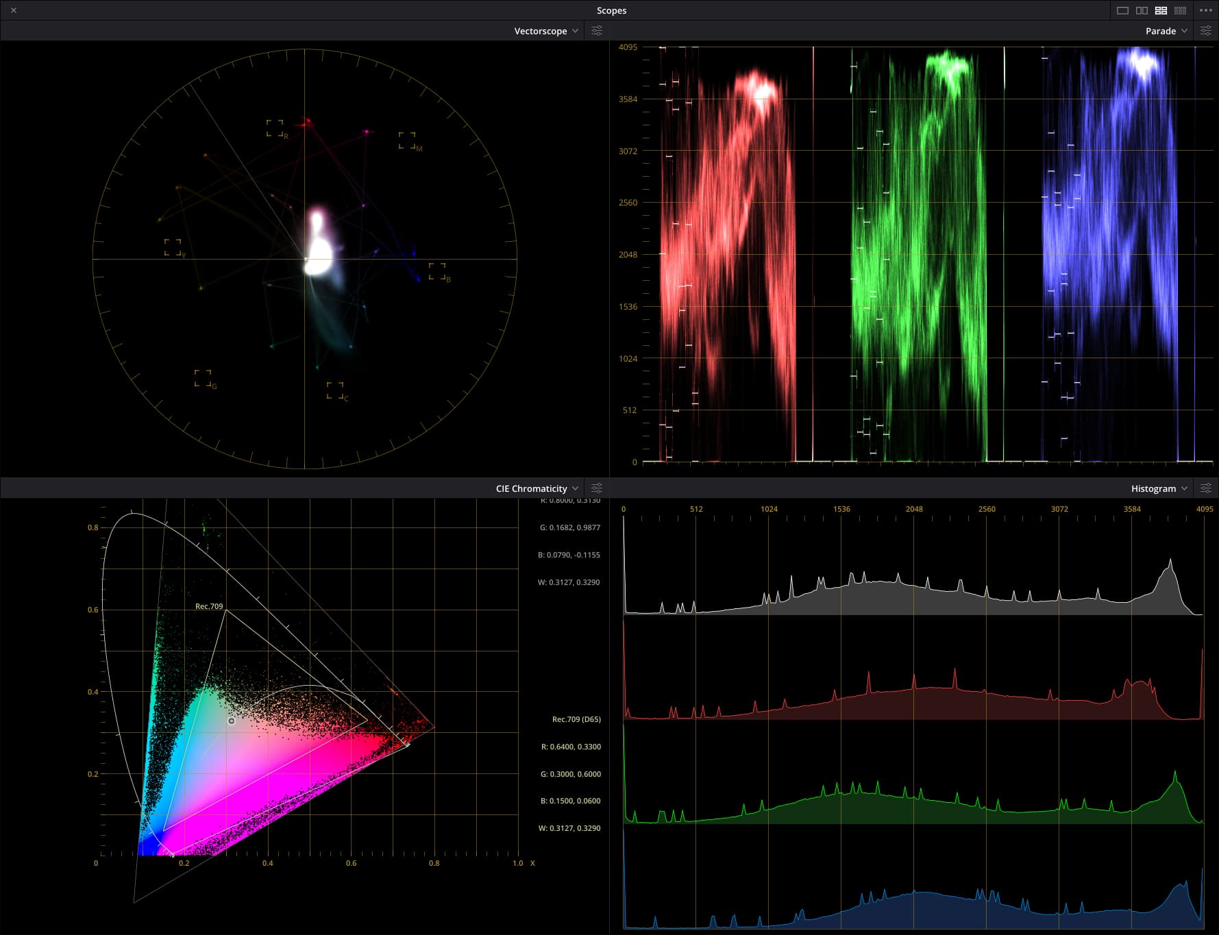
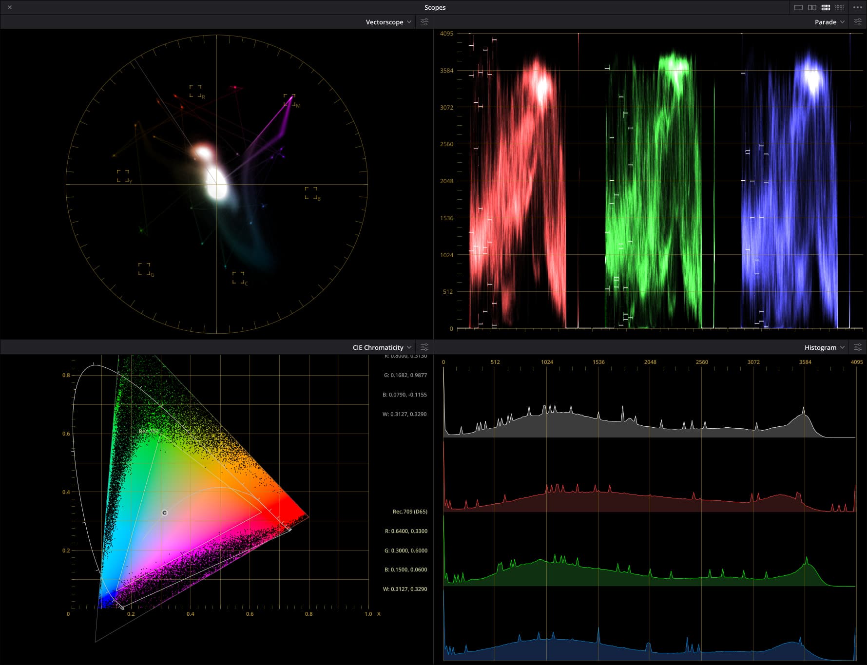
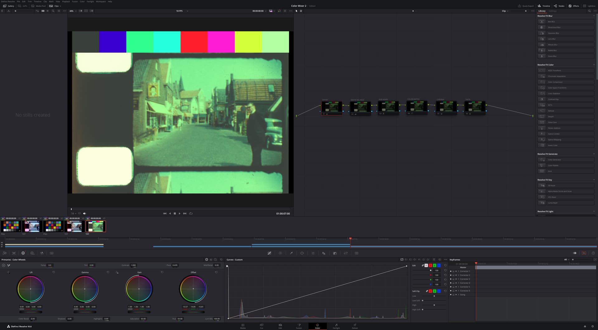
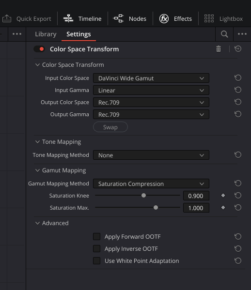
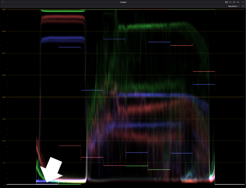
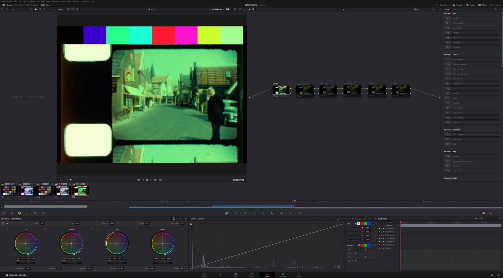
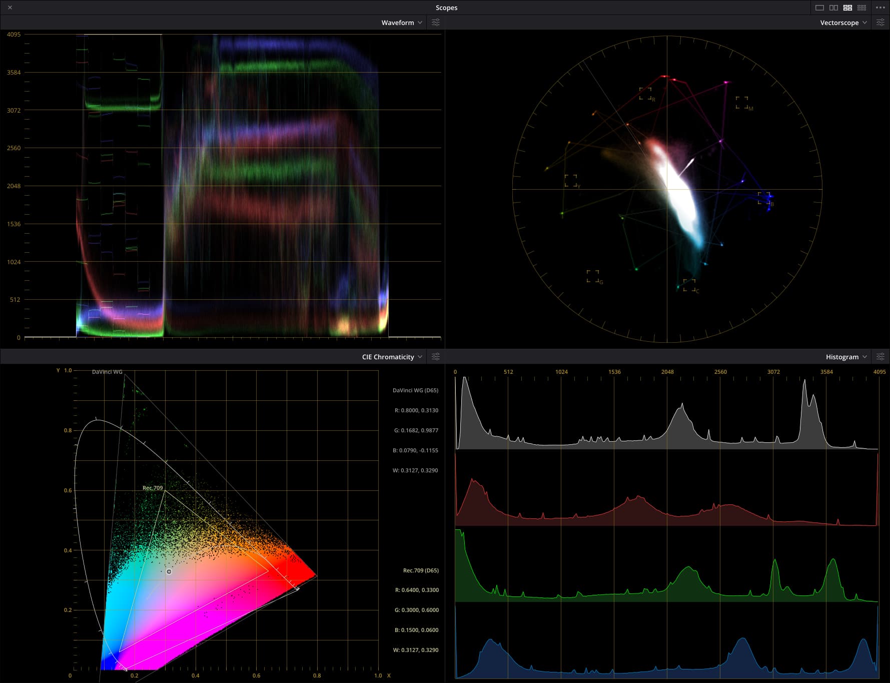
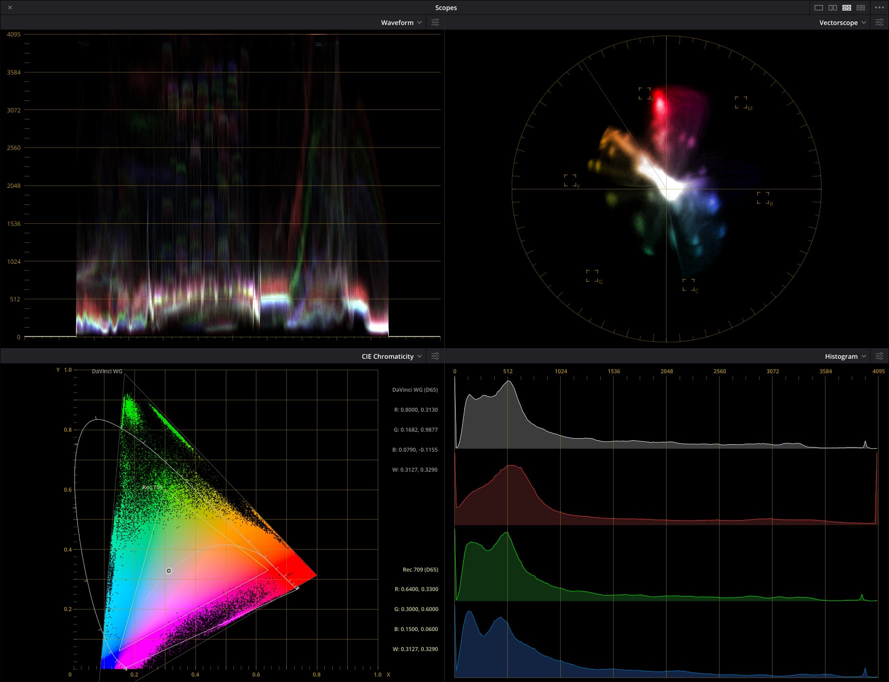
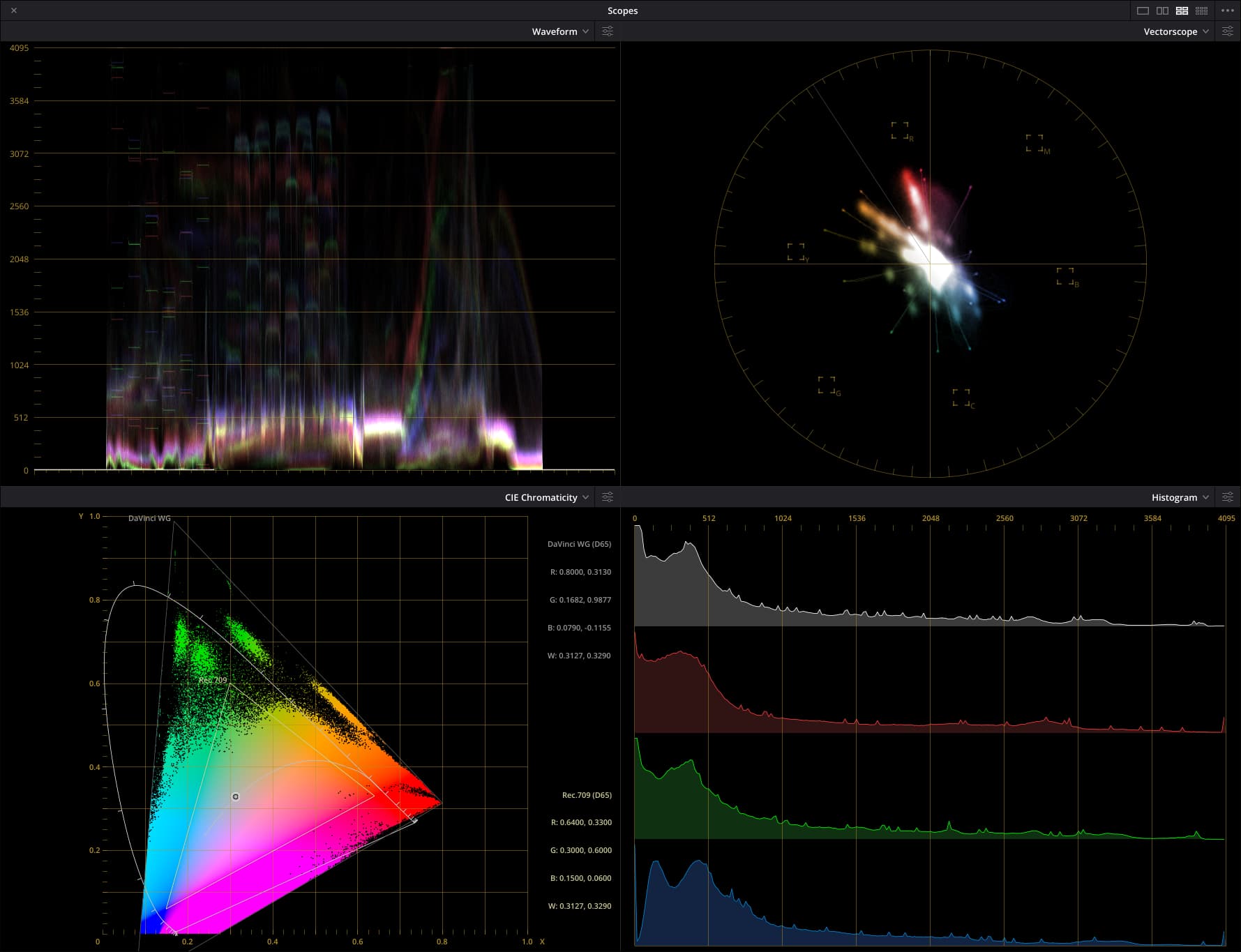
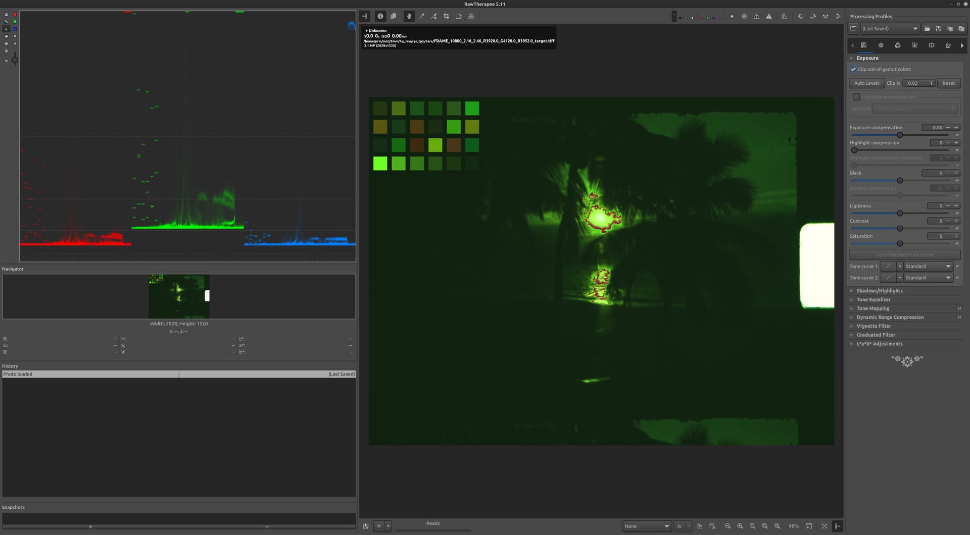
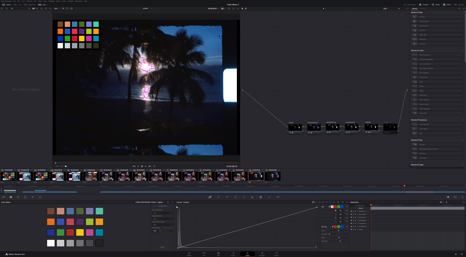
It is important to understand that in both cases, the resulting TIFF completely disregards color science information. It is also important to note that the raw values are what the sensor provided, including a pedestal (offset to the black levels of each channel), and that these are linear values (no gamma). In other words, from here, the processing pipeline that one chooses (either python coding or using something like Davinci Resolve) have to carefully consider the nature of the source data.

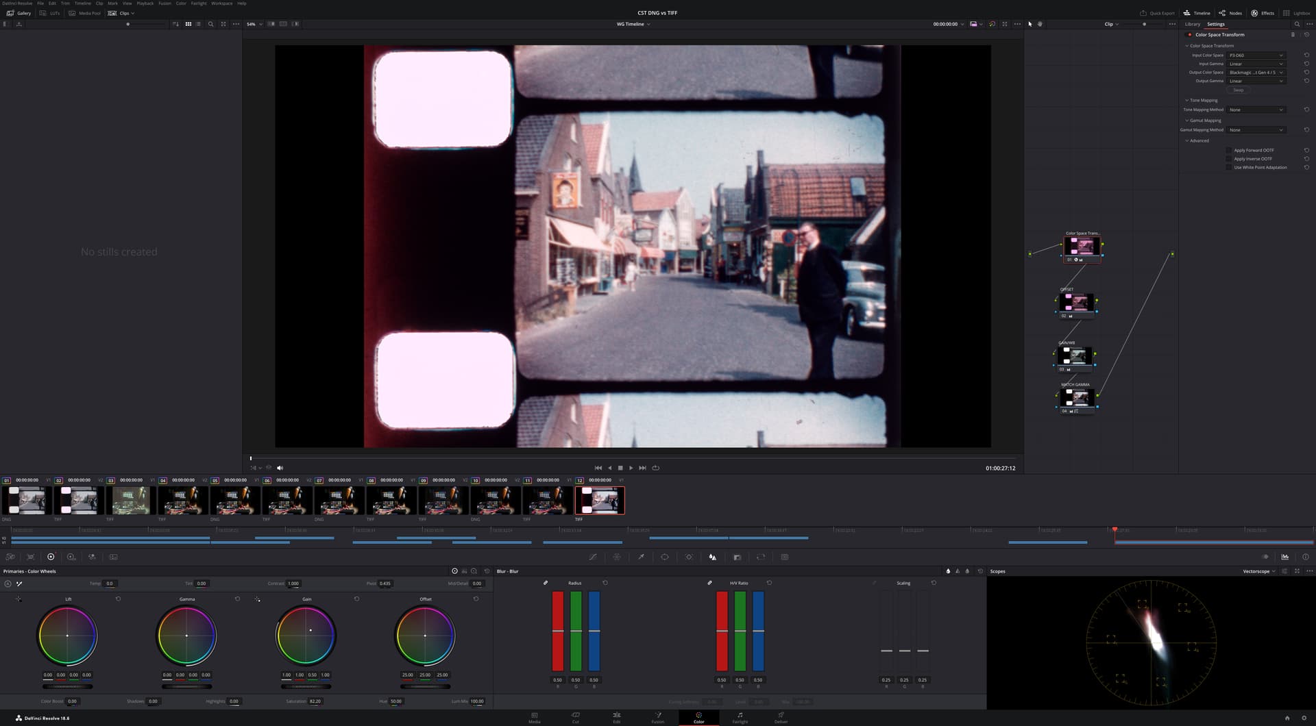
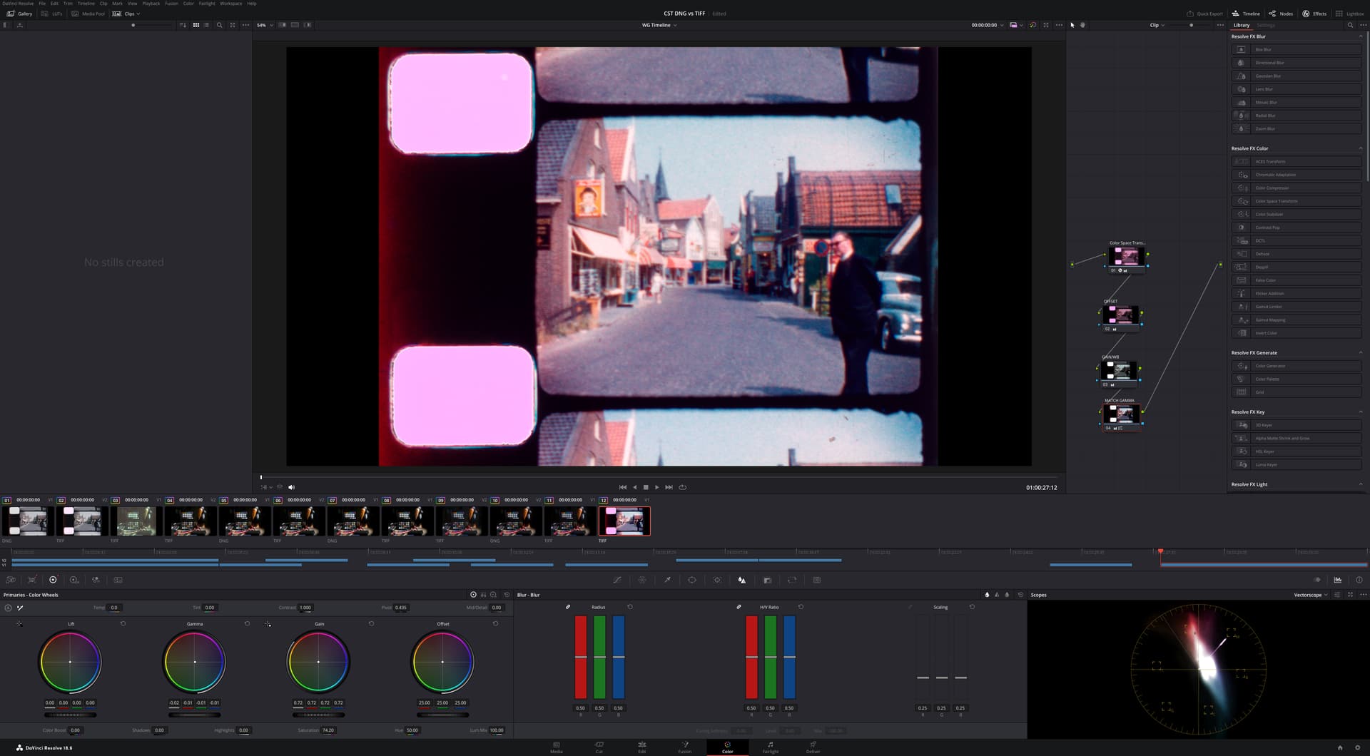
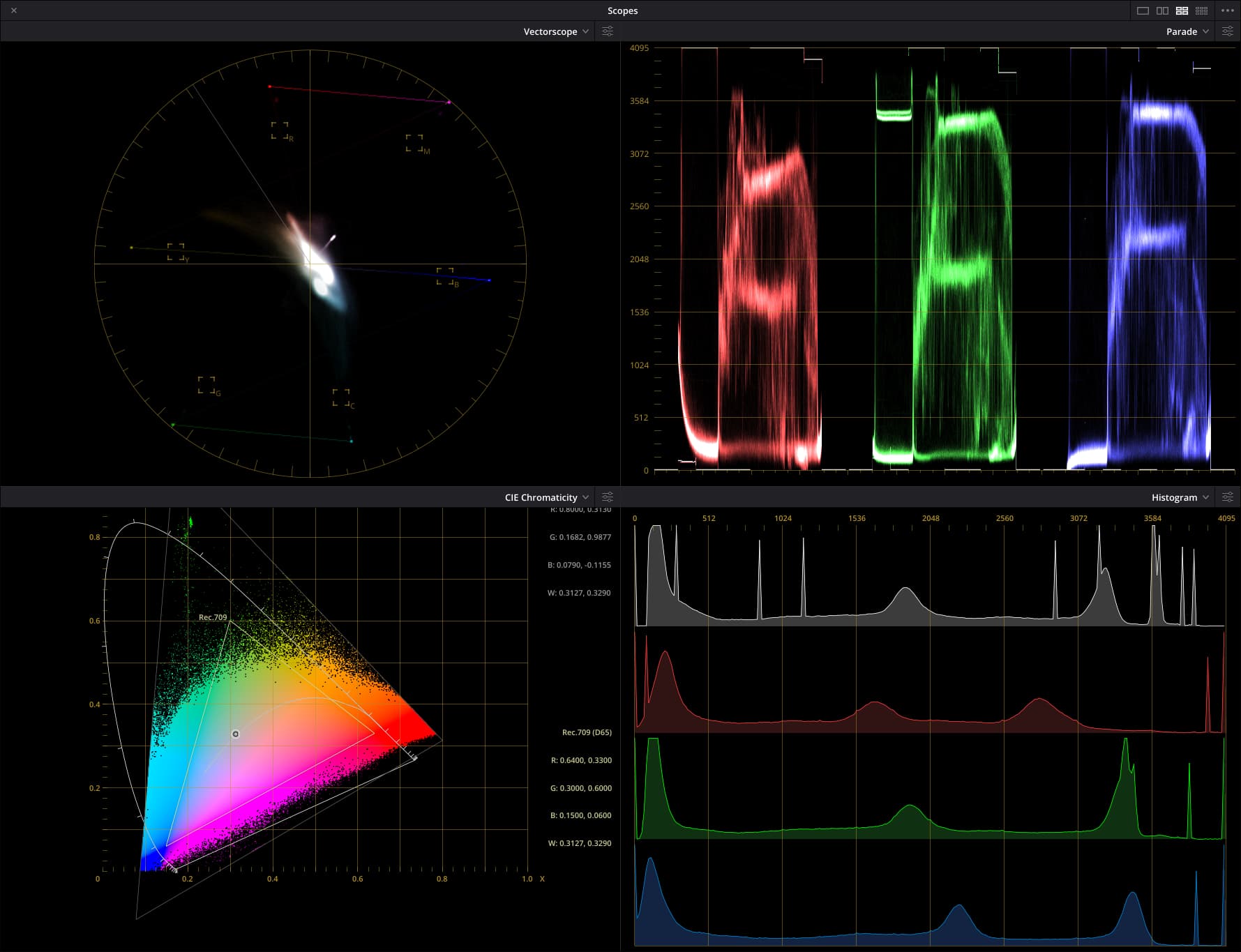
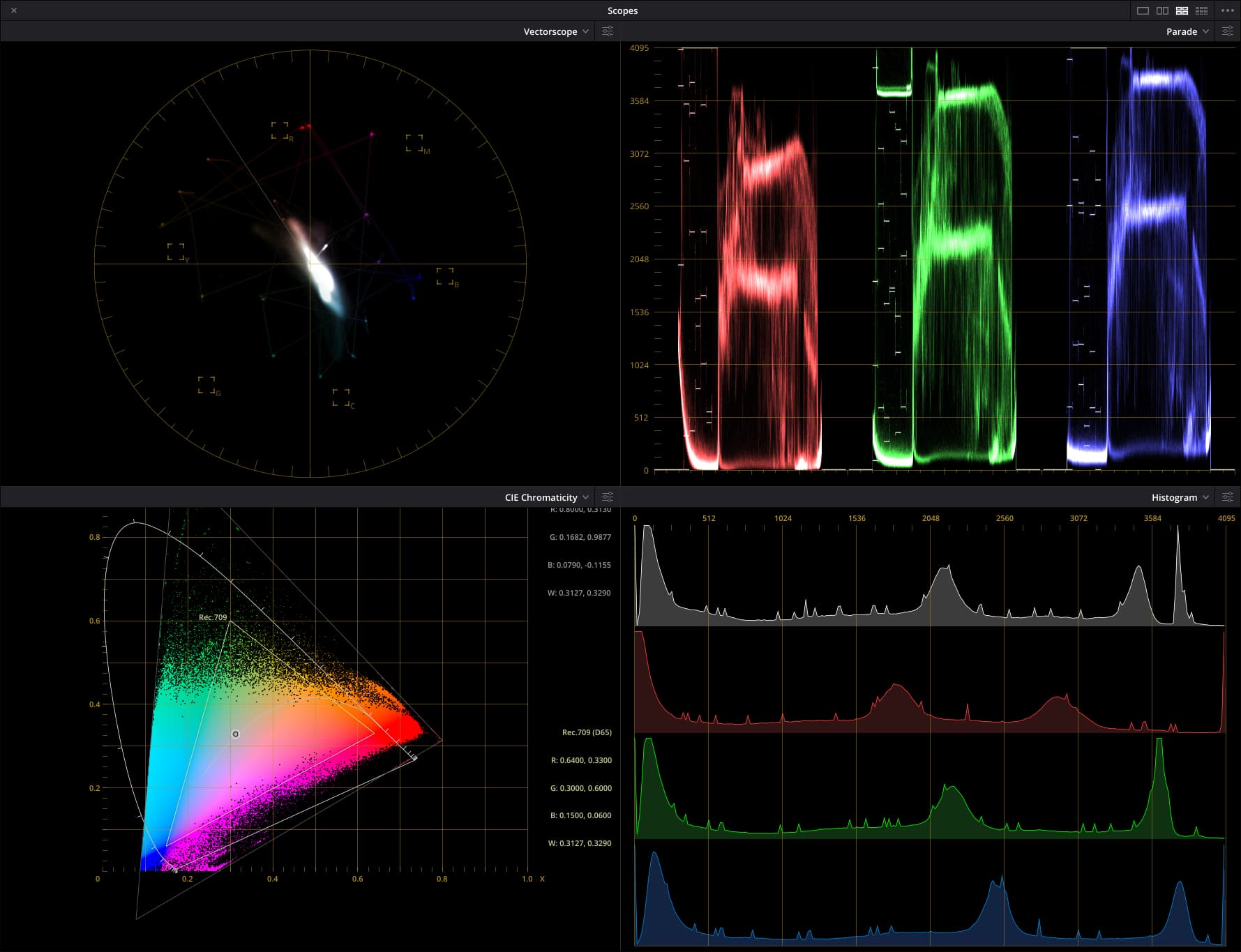
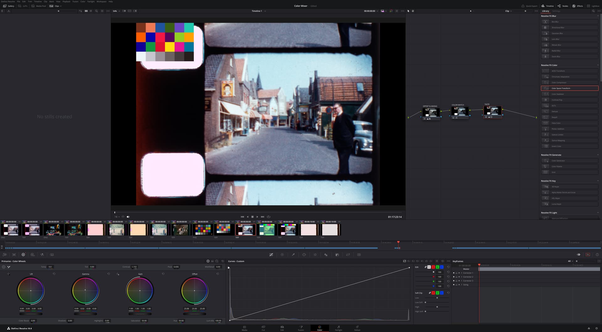
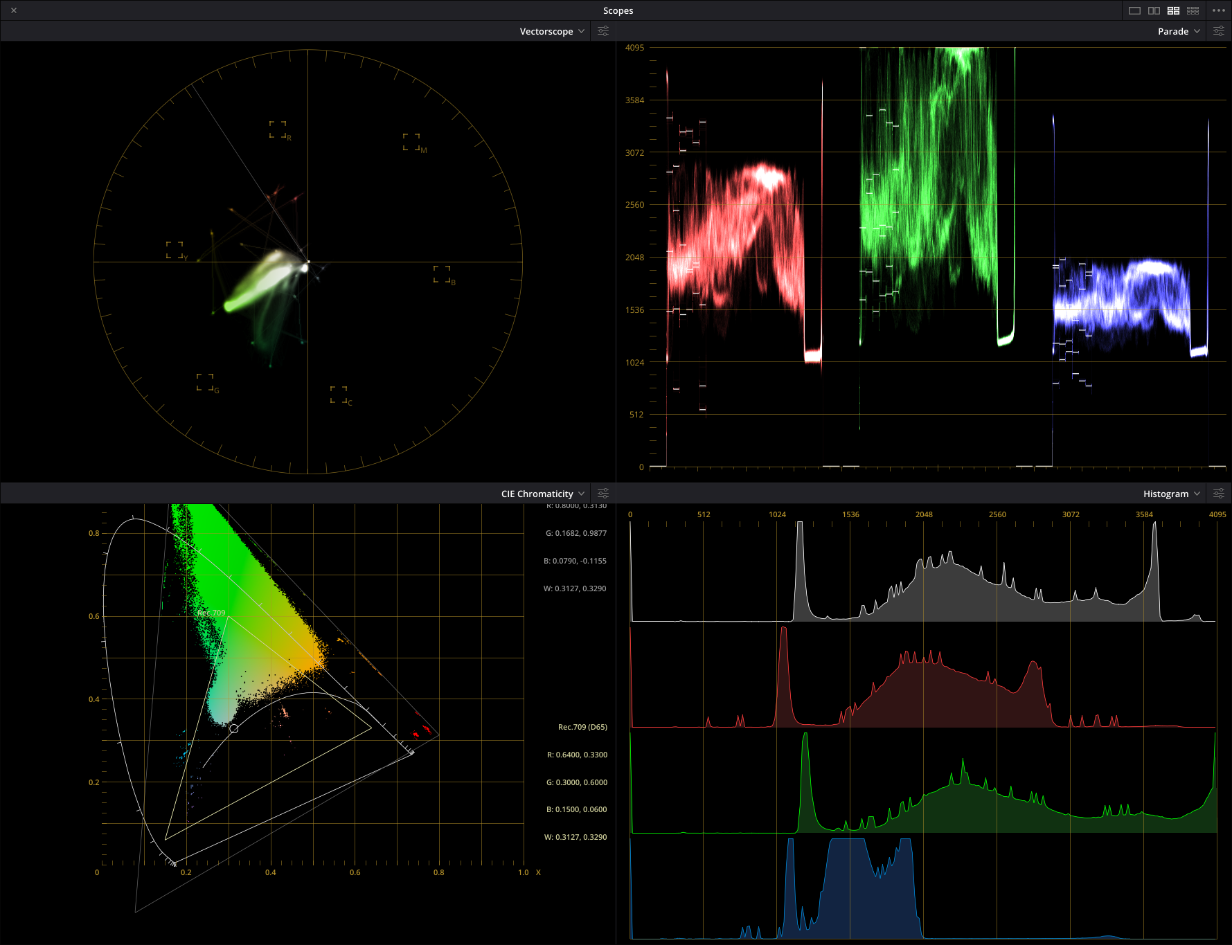
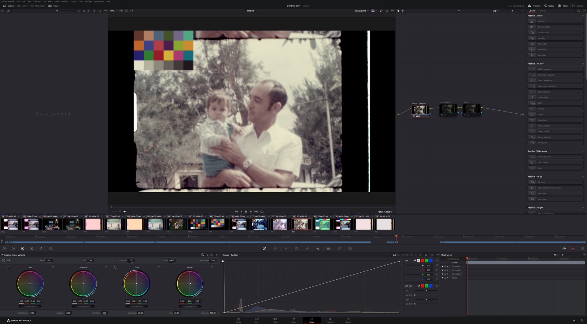
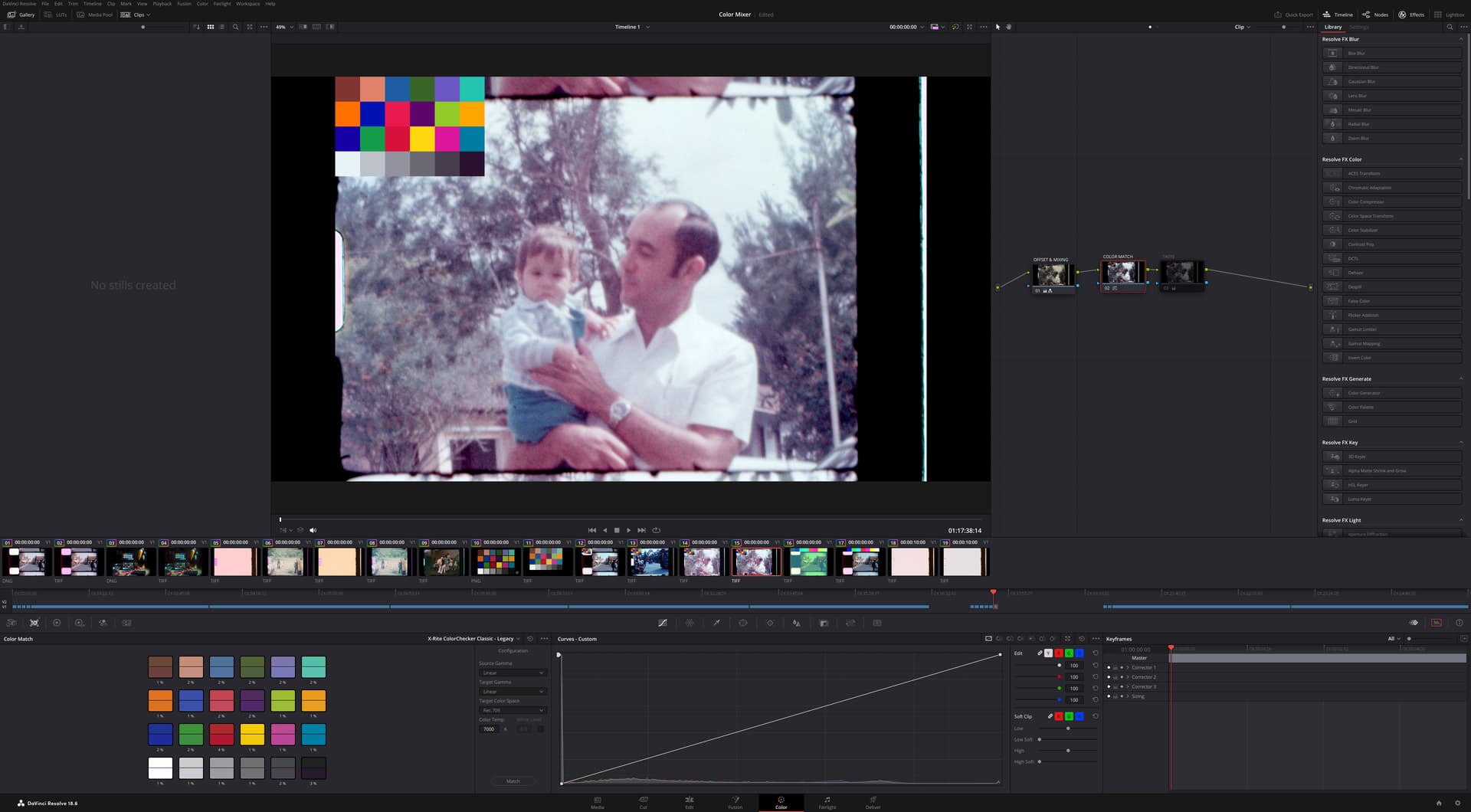
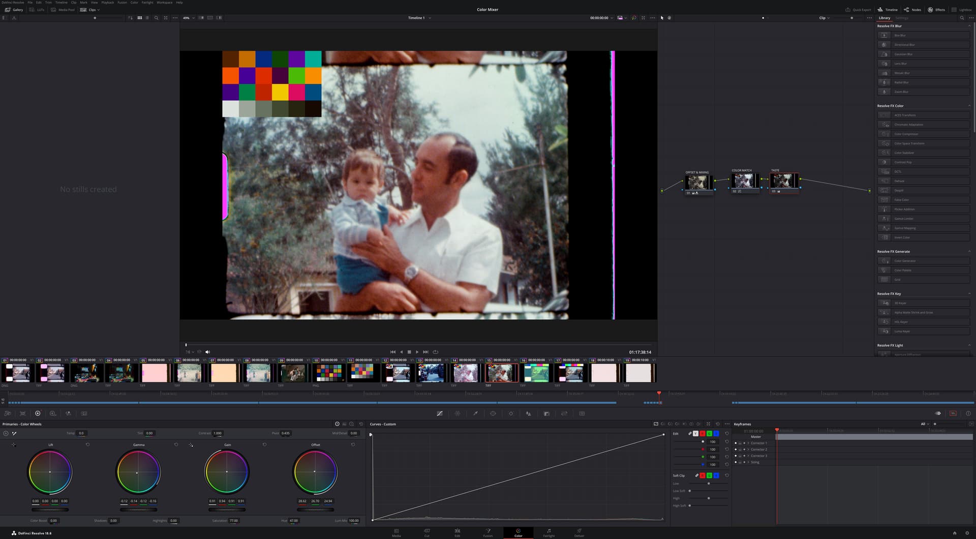
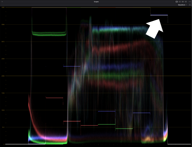
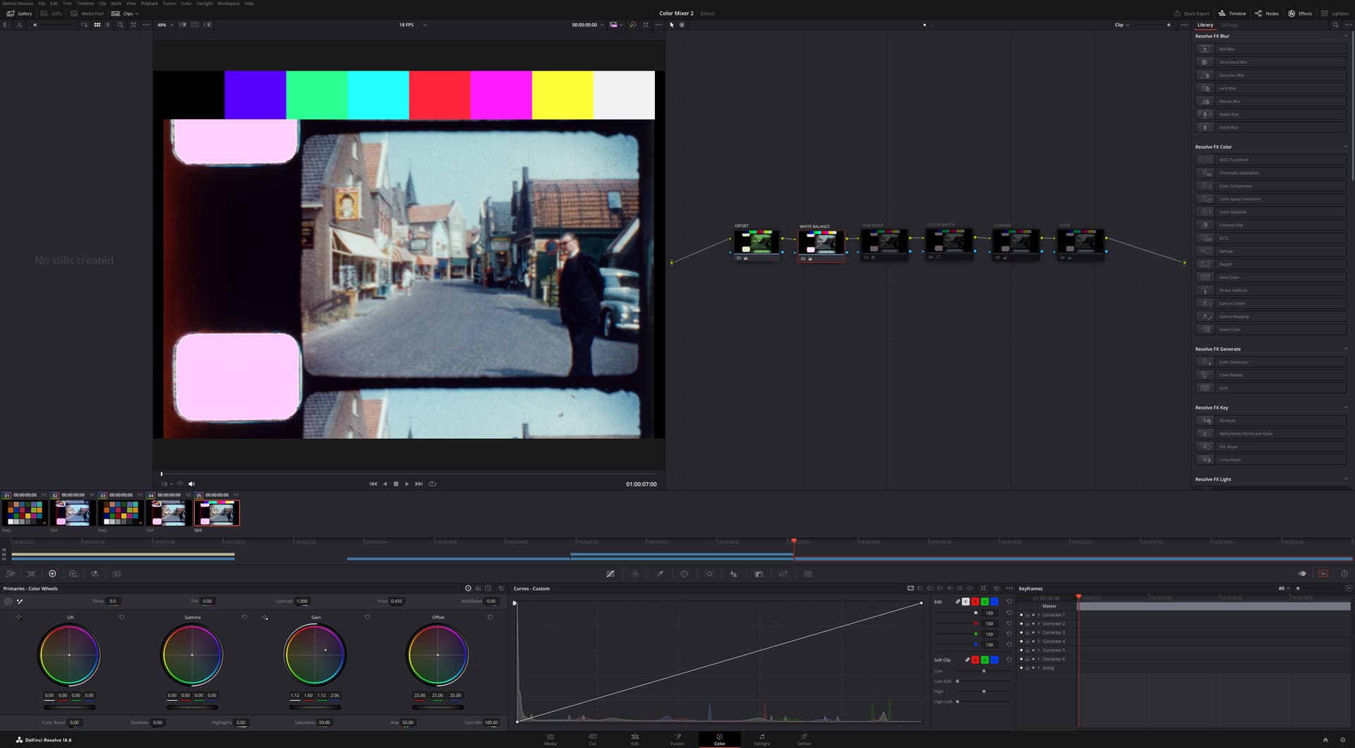
The second alternative preserves the color science, and the full resolution bayer (saved as the DNG). Consider that the raw values are subject to the processing to create (picamera2) and extract (rawpy) the DNG information.

The first alternative is a practical method to store -without any color science- the values as provided by the sensor. Note that Green 1 and Green 2 are combined into a single value, increasing the green channel bit depth, but effectively reducing the image spatial resolution, which was not saved otherwise (like when the DNG is saved).

@verlakasalt hope this provides the additional information you were looking for.

3 Likes

Hope everyone is having a colorful wide-gamut 2025!

I did some experiments with the intention of using Rolf’s @cpixip xp24_full.dng as reference to develop a processing path for the raw values TIFF in Resolve, and to that effect, the raw values of the DNG file were extracted into a TIFF without no other color information.

The script used to extract the TIFF was:

## Remix from @cpixip script to analyze DNG files.
import numpy as np

import rawpy
import tifffile

path = r'xp24_full.dng'

inputFile = input("Set raw file to analyse ['%s'] > "%path)
inputFile = inputFile or path
outputFile = inputFile+".tiff"    
# opening the raw image file
rawfile = rawpy.imread(inputFile)    
print ('Rawfile Pattern',rawfile.raw_pattern[0][0])
print ('Rawfile shape', rawfile.raw_image_visible.shape)

# get the raw bayer 
bayer_raw = rawfile.raw_image_visible
bayer_raw_16 = bayer_raw.astype(np.uint16)
rgb_frame = np.zeros(( 1520,2028,3),dtype=np.uint16)

# quick-and-dirty debayer
if rawfile.raw_pattern[0][0]==2:

    # this is for the HQ camera
    red    =  bayer_raw_16[1::2, 1::2]                                 # Red
    green1 =  bayer_raw_16[0::2, 1::2]                                 # Gr/Green1
    green2 =  bayer_raw_16[1::2, 0::2]                                 # Gb/Green2
    blue   =  bayer_raw_16[0::2, 0::2]                                 # Blue

elif rawfile.raw_pattern[0][0]==0:

    # ... and this one for the Canon 70D, IXUS 110 IS, Canon EOS 1100D, Nikon D850
    red    =  bayer_raw_16[0::2, 0::2]                                 # Red
    green1 =  bayer_raw_16[0::2, 1::2]                                 # Gr/Green1
    green2 =  bayer_raw_16[1::2, 0::2]                                 # Gb/Green2
    blue   =  bayer_raw_16[1::2, 1::2]                                 # Blue

elif rawfile.raw_pattern[0][0]==1:

    # ... and this one for the Sony
    red    =  bayer_raw_16[0::2, 1::2]                                 # red
    green1 =  bayer_raw_16[0::2, 0::2]                                 # Gr/Green1
    green2 =  bayer_raw_16[1::2, 1::2]                                 # Gb/Green2
    blue   =  bayer_raw_16[1::2, 0::2] 

elif rawfile.raw_pattern[0][0]==3: #HQ SRGGB12

    red    =  bayer_raw_16[1::2, 0::2]                                 # red
    green1 =  bayer_raw_16[0::2, 0::2]                                 # Gr/Green1
    green2 =  bayer_raw_16[1::2, 1::2]                                 # Gb/Green2
    blue   =  bayer_raw_16[0::2, 1::2] 

else: 
    print('Unknown filter array encountered!!')

rgb_frame[:,:,2] = (blue)<<4
rgb_frame[:,:,0] = (red)<<4
rgb_frame[:,:,1] = ((green1+green2))<<3
    
tifffile.imwrite(outputFile, rgb_frame, compression=None)

The starting point was the Resolve processing settings in this post. But after experimenting a bit instead of using the Davinci Wide Gamut color space, the Blackmagic Design Wide Gamut Gen 4/5 appear to have slightly wider range, and I swapped all the nodes and color transformations that in the posting use wide gamut to Gen 4/5.

The TIFF, extracted from the DNG, has no color space information. The DNG in the posting is being developed to P3 D60, and then the color transformation node goes from it to the wide gamut. In the case of the TIFF, there is no developer, only direct raw values. To that effect, the node sequence is first a Color Space Transform with input P3-D60, and output of Blackmagic Design Wide Gamut Gen 4/5. The CST with these settings dimmed the chroma, and to compensate saturation was increased to 82.20 in the CST node. With more iterations/time to experiment, saturation may be reduced in this node.

Following the sequence comparison, with Vectorscope set to 2X.
DNG REFERENCE


xp24_dng_match

TIFF from values extracted from DNG


xp24_dng_match

Street TIFF
The node MATCH GAMMA takes its settings from the xp24_full TIFF Color Match node.


Note that the resulting TIFF pipeline (after the initial chroma increase) results in a more saturated picture than the DNG, and to that effect Saturation was reduced in the last node to match the DNG. Again, iterating between the Saturation setting on the first and last node may yield better results.

There is plenty of range in chroma -without clipping- on the last node.

To recap.
The well-known and challenging xp24_full.dng is the matching reference.
The raw values of xp_24 were extracted, into a 16 bit TIFF.
The street scene is a test capture directly into 16-bit TIFF is a test image to validate results.

Processing pipe in Davinci Resolve was set for wide gamut, with a final/downstream conversion from wide gamut to rec709.
The DNG file is developed into P3-60 color space, and processed/color match. The reference.

The 16 bit TIFF is extracted from the DNG, brought into resolve color. Although the TIFF is not using any particular color space, the first node is a Color Space Transform to wide gamut, and good results were obtained setting P3-D60 as input. Nodes for OFFSET, GAIN/WB condition the raw values before a final node of COLOR MATCH/GAMMA is used for fine tuning. The color chart in the picture is used to adjust the TIFF final MATCH GAMMA node.

To process the street file, the settings (all nodes) from the x24 TIFF are applied to the street TIFF. The first and last nodes will be unchanged to preserve the match between DNG and TIFF obtained with xp24 set. The nodes for OFFSET and GAIN/WB will need to be adjusted to balance the RGB channel raw values before the MATCH GAMMA node does the final matching.

Note: the beak has a spot that is clipped, unlike the DNG which addresses this with the developer, the TIFF clipping is visible.

2 Likes

Hi Pablo (@PM490) - I must confess that I have difficulties to properly understand your approach.

For starters, if I understand your tiff-approach correctly, you are throwing away all of the additional information available in the capture (blacklevel/whitebalance/ccm) to hand-tune a processing path in such a way that it looks identical to the standard way of working with raw files? If so, why not just work with the reference?

Well, that is actually not the case - DaVinci WG is the larger working space. You can check this by using the “CIE Chromaticity” setting on the “Scopes” tab which allows you to display two different color spaces with their parameters (see below).

Note that in the approach I sketched, the timeline working space does only mildly matter. Only the way certain sliders/modules work will change, but not much the overall result. That is build-in into DaVinci as it uses 32bit floats with no clipping (mostly: stay away from LUTs, for example).

Continueing:

I would say that it has, actually in two different ways. First of all, it’s what the camera saw with it’s given Bayer filter array looking at the scene. So in a sense a very well defined image. And in fact, the mapping from raw Bayer toward a RGB-image is based on that well-defined mapping of spectral data. Given, it’s complicated, like

  1. Adjust for illumination with appropriate whitebalancing coefficients (red and blue channel gains).
  2. Transform to device-independent, observer centered XYZ-space.
  3. Transform from XYZ to the desired output color space.

(I skipped a few things here…). In fact, the Color Matrix 1 hidden in the .dng-file is exactly describing the transformation from linear sRGB to cameraRGB while the As Shot Neutral tag specifies the transformation from cameraRGB to raw Bayer data (together with the blacklevel and whitelevel data in the .dng).

So in a way, the raw Bayer data (your .tiff-data) is defined - both in terms of color gamut as well as gamma (linear, for that matter). Of course, you can ignore that information…

Also note that you are implicitly imprinting a color space to your footage as soon as you insert the material into a Davinci timeline. There’s no way around this. The RGB data will be interpreted as whatever you have set your timeline color space to.

Let’s recap shortly what a color space is. It consists of four parameters: a whitepoint and the color coordinates of the three primaries. The whitepoint specifies the values which correspond to “white”, that is maximal brighness with no color. The primaries span the space of all representable colors. You can actually see this in DaVinci’s “Scope” tab when selecting “CIE Chromaticity”:


Here, actually two color spaces and their properties are displayed - the DaVinci WG as well as Rec.709. And you see the coordinates of the primaries (RGB) as well as the whitepoint for both color spaces (which is identical in this case).

Now if you assign an arbitrary color space to your data, the colors will certainly not be correct. The correct way to go from one color space to another one is to use a CST node (there are also LUTs available, but as they introduce clipping, I am trying to avoid them).

In a CST, there is another selection you have to make which also changes the interpretation of color values: the input and output gamma. Again, you want to use the correct setting here, not something arbitrary. Let’s see in detail why I set up my processing in this post the way I did:

  1. I set up the timeline color space to DaVinci WG with the gamma DaVinci Intermediate - that basically instructs DaVinci to do all computations in this space. Choosing here other options will change the way certain sliders/modules will work, but most of the time, it’s rather irrelevant what you choose here.
  2. I instructed the raw converter to output P3 D60 as color space - in fact, I could have used here Rec.709 as well - that does not matter too much (but see discussion below in point 5.).
  3. I requested as “Gamma” Linear from the converter. Here as well, I could have chosen a different setting, it would not matter (as long as the clip’s CST matches). I chose Linear to have an easier setup on the clip’s CST node.
  4. My monitor is calibrated to Rec.709 and I do output to this - so at the timeline node graph, I inserted a CST towards the output/display space in order to grade and output the correct colors. Indeed, input is set on this CST to Use timeline and output to Rec.709.
  5. Finally, on the clip’s node tree, I inserted right after the input node (which delivers P3 D60/Linear a CST transforming this into the timeline (Use timeline). Important here is that both “Tone Mapping” as well as “Gamut Mapping” are set to None and both Apply Forward OOTF and Apply Inverse OOTF are unchecked. If I would have selected color space Rec.709 instead of Linear in step 3 when setting up the raw input module, during the clip’s corresponding CST setup with Rec.709, the Apply Forward OOTF would have automatically be checked by DaVinci - that’s why I choose Linear in the first place - the Apply Forward OOTF is in this case left untouched.

After the clips’s CST, the raw data is in the DaVinci timeline color space, that is DaVinci WG - which is more than enough for all practial means. Due to the timeline’s CST, that data is transformed right before output into the color space I need, Rec.709. That’s the setup I described and I am working with. I hope this clarifies things a little bit.

So… - I am not sure what you are trying to achieve with your .tiff-processing. The color processing from .dng-files to any other desired color space/output gamma is well-defined. The data embedded in the .dng is derived from your scanner settings and the tuning file you are using. It is optimized in such a way that the colors come out very close to the original colors of the scene (provided the whitebalance is correct). So what would be the advantage of the .tiff-processing scheme, manually tuning things?

Hi Rolf, thank you for taking the time to share your knowledge on the subject, mine is quite limited.

You are right. What I probably did -if I am understanding it now- was compress the color space, and hence it appeared to have less clipping in the smaller color space (Rec709) in the timeline node. My bad.

Agree.

From what I understood, if a transform note is first, the input color space to output color space will determine how the RGB data is translated into the timeline color space.

That is what I did in the experiment with TIFF. However, without a DNG developer (TIFF), is P3 D60 the best input color space of the CST node?

A lot of things. But mostly balance all these things in the limited computer power of a RPi 4.

  • Have a non-arbitrary black offset/clipping defined post-capture.
  • Capturing a raw array, debayer/binning, and saving as a 16 bit TIFF is much faster than saving a DNG.
  • The red channel of the HQ is quite noisy. Stacking a DNG is slow and storage consuming. Stacking the raw data to be saved as TIFF is orders of magnitude faster. I do not plan to do this for every reel, but there are some that warrant the extra work.
  • Capturing color channels with different/individual light settings.
  • The transport does not have hardware sprocket hole detection, it is extracted from image data. Extracting the area-of-interest information from the raw capture data allows for adjustments at the sensor frame rate.
  • Having the sprocket and film edge location, transport-image-stabilization is a simple cropping formula with little or no additional processing time in the RPi4.
  • Eliminate the uncertainty with libcamera2 processing/changes.
  • Use of more accurate color processing pipeline (Resolve).

Does the Color Matrix 1 require prior offset subtraction?
I am still learning Resolve, is there a mechanism to apply a color matrix to include color matrix 1?

In my ideal world I would like to do as little as possible in the RPi, and do as much as possible in Resolve. More over, would like to have a processing pipeline calibrating the transfrom from raw data to Davinci WG directly.

In the context of faded films, I have a good enough processing pipeline already, but would like to have some known calibrated processing, since not everything is faded.

1 Like

Well, DaVinci is a complex program and I might not understand it either to the fullest. But I think this is the way input data is inserted into the timeline:

  1. The input node reads the data. There is the possibility to assign an input LUT to the data, on the “Media page”. I never use this. If this LUT is not specificed (the standard case), processing starts with the following step:

  2. The input node pipes the data directly into the timeline. So whatever timeline space is selected is used for the interpretation of the incoming data. Under normal circumstances, incoming data will be rec709 or sRGB, and if you work with defaults, the timeline color space will be rec709/sRGB as well. So all is good in this case. No need to worry about color spaces. However: we did choose to work in DaVinci WG - so the data from the input node would be interpreted as DaVinci WG - which is not correct. We need to get the data into the correct color space - this is the reason the first processing node in the clip’s processing pipeline is doing a color space transform (CST).

  3. A CST needs two things: a specification of the input color space, and a specification of the output color space. Now, as we have set up the raw reader to output P3 D60, this is the correct input color space for our CST. And of course, since we selected as gamma curve Linear, we need to select this as well in the input section. The output section just uses for both settings the Use timeline. So after the input CST, your data ends up in the correct color space. Which is the color space selected for the timeline: DaVinci WG. All processing in your timeline will happen in this color space. Note that you want to make sure that neither Apply Forward OOTF nor Apply Inverse OOTF is checked and that both “Tone Mapping” and “Gamut Mapping” are set to None. Be sure to check Use White Point Adaption. This will shift the whitepoint from our input whitepoint D60 towards the timeline default D65(a minor change).

  4. DaVinci WG is fine as timeline color space, but rendering out just like that is not going to work. The images will be dull and desaturated - even in preview. In order to be usable, you will need a secondary CST which will be applied to all data in your timeline after all effects. It therefore needs to be located at the very end of the timelines node graph (usually, it would be anyway the only node in this graph). This CST has as input the Use timeline setting and as output Rec.709. Here, the Apply Inverse OOTF needs to be checked. I set the “Tone Mapping” to None and the “Gamut Mapping” to Saturation Compression. The later will gently roll off too high saturation values exceeding the output color space - this is exactly what I want.

Hope that clarifies a little bit the data flow. The raw reader pipes into the timeline raw data developed into P3 D60 - even data which lands outside this color gamut, as DaVinci is not clipping during processing (as long as you are staying away from LUTs). The CST following the input node takes all the data and aligns it to the chosen color space of the timeline. Since that space is larger than P3 D60, we in fact recover some colors which would otherwise be lost. (At least I hope so… :innocent:)

But in order to grade and output the material correctly, we have to insert at the very end of our processing pipeline yet another CST - namely the one which maps from our timeline color space into what we want to grade into. In our case Rec.709. If my monitor wasn’t calibrated to rec.709 but rec.2020, for example, I could opt instead to map here into Rec.2020. Of course, I won’t, as most distribution channels currently support only rec.709 for sure - higher color spaces are always a gamble at this point in time.

Frankly, there is no correct color space for your .tiff-data. For starters, it still includes the blacklevel, so zero intensity is not represented by a zero pixel value. Second, there is no whitebalancing applied, so there is still the dependency on your illumination. Given, you can come up with a grade which mimics the necessary steps taken during raw processing - but only up to a point.

Well, it’s not really arbitrary. It’s just not as precise as we would like it to be. Cooling down a sensor chip for example changes the blacklevel - which more advanced cameras notice, as they use blackend pixels on the sensor for blacklevel estimation. Our sensor does not do it. Is it crucial? Probably not.

I do not think so. I have RP5 as well as RP4 machines capturing in raw and saving as .dng. Well, actually the .dng is not saved but send via LAN to a PC. Maybe that’s the difference. It’s been a while since I did this, might have to recheck this.

Yes, indeed. Usually, the red channel uses the largest gain multiplier. In my case, processing of .dng-files is never done on a RP, but a faster Win-machine.

Uh. That might be something interesting. But how do you do your color science than? Of course, grading by eye is always a possiblity…

Remember that libcamera/picamera2 delivers you a secondary, already processed image with basically no additional resource consumption (the “main” profile). You can pair that with my sprocket detektion algorithm posted elsewhere on the forum to get a real-time sprocket detection on a RP4.

Hmmm. I guess we have a different approach here. I only use the RP4/5 as a capturing device and do all the heavy processing on my WinPC.

:slight_smile: - that’s a big plus! I usually update a secondary RP4 and see what breaking changes were introduced by new picamera2 updates. Only after I am confident that I solved all issues I actually update my film scanner. Sometimes, as RP4 and RP5 are using slightly different software bases, I still get some unpleasant surprises after an update…

Yes. Not only that, but it requires to take into account the data in the As Shot Neutral-tag as well before applying the CM1. That is, the red and blue channel gains need to be applied before. And, to make things even more complicated, the CM1 transforms from sRGB to whitebalanced camera raw - which is the wrong way around. The matrix needs to be inverted to be useful. And, to make things even a little bit more involved: for the whitepoints to match, the matrix needs to be normalized in a certain way. Don’t ask me why… Oh, and I forgot: you need to throw in a CAT (color adaption transform) matrix in that box as well… (all this is and more is handled by any raw developing software)

Well, that’s my approach. The RP simply captures a frame and sends it as .dng-file directly to a Win-PC for storage, via LAN. Capturing a 15 m S8-roll takes about 3 hours with my scanner, as I have to wait long enough for vibrations induced by the film advance to settle (should not used plastic parts for my scanner…). Next step is DaVinci, converting the .dng-files to rec709-files, which takes about 30 mins on my PC (depends mostly on the hard disks). Raw development and some initial color grading is already done at this point. Data is output as rec.709 tiff-files. After this, a Python prg locates the sprocket position and removes remaining jitter (again about 30 mins). Next step (yet another timeline in DaVinci) is the final color grading of the footage, including cut out of the image frame. Rendering time again about 30 mins, less if I have space available on faster hard disks (which I usually never have…)

That’s actually the point I was trying to make: the scheme I was describing in my other post is exactly doing this. It converts captured .dng-files into rec.709 images, with sensible adaptions (the Saturation Compression in the timelines CST) if the colors are too extreme. The color science used (the inverse of CM1, essentially) is based on the optimizations done while developing the scientific tuning file for the HQ sensor.

Here’s again an overview of my current setup. The clips are developed with this setting:


The clip input CST is set up like this:

and the timeline features this as CST setting:

1 Like

Thank you for taking the time to provide feedback and share your knowledge.

In our film scanning world the light is set. One could have consistent files as long as the light temperature remains the same. That is in part the idea of shifting the calibration and processing away from the libcamera2 and over to Resolve.

Certainly, and your post has been extremely helpful to learn more about Davinci Resolve settings. And that scheme is perfect for DNG.

And the scheme is also a solid template foundation to work the raw TIFF values.
But because of the limitations of the TIFF, I have some gaps to fill to simplify the grading of various faded/unfaded sources in TIFF.

Doing so only for the purpose of improving the color range… I have one film that merits trying every trick… and grading would certainly be by eye (and with lots of patience), but if the channels are somewhat balanced, it actually becomes closer to an RGB.

The CM1 is not what I had in mind… thanks for clearing that up for me.

In the old analog world, if my recollection is correct, there was a color matrix right after the RGB preamplifiers of the sensor/tube, which in the NTSC world derived the I and Q.

The bayer filtering is imperfect, and the output of the IMX477 channels includes a blend (crosstalk) of other channels.

The RGB mixer in Davinci Resolve is what I was missing/looking for.
For the TIFF I am now using it on the first node along with offset, and the results are very encouraging (film below is quite faded).

2 Likes

Additional Experiment

Among the challenges of working with raw values is that the array has a pedestal (offset) and that the levels of RGB are not balanced. In the context of film scanning, if the illuminant remains unchanged, that sets the white balance gains.

Ideally, a color chart target would provide a reference to calibrate against. But I do not have one that would represent the film (translucid).

In an effort to stablish some reference for the process, I had the idea of simulating color bars adjusted to the maximum value levels of each RGB channel in an area of interest (excluding the sprocket hole), providing a simulated target to color balance with Resolve.

Would like to share the initial results as the idea has potential for imprinting reference patches, or creating a simulated color calibration chart.

A simple script was used to generate a new TIFF from a source image, to the image with the imprinted simulated color bars.

import tifffile as tiff
import numpy as np

# Define the file name of the saved TIFF image
file_name = "bars/tpx_street.tiff"

# Open the TIFF file and load its content into a NumPy array
try:
    with tiff.TiffFile(file_name) as tif:
        tiff_array = tif.asarray()

    image_shape = tiff_array.shape
#    aoi_crop = 200
#    aoi_rgb = tiff_array[aoi_crop:image_shape[0]-aoi_crop, aoi_crop:image_shape[1]-aoi_crop, : ]
    aoi_crop = 20
    aoi_rgb = tiff_array[0:image_shape[0]-aoi_crop, 600:image_shape[1]-aoi_crop, : ]

 
    print (f"Array shape: {tiff_array.shape}")

    print(f"Array dtype: {tiff_array.dtype}")


    print('Full Frame D-aoi_cropataoi_crop')
    print('_______________')
    print('             Minimum red   : ',tiff_array[:,:,0].min())
    print('             Maximum red   : ',tiff_array[:,:,0].max())
    print()
    print('             Minimum green : ',tiff_array[:,:,1].min())
    print('             Maximum green : ',tiff_array[:,:,1].max())
    print()
    print('             Minimum blue  : ',tiff_array[:,:,2].min())
    print('             Maximum blue  : ',tiff_array[:,:,2].max())

    rgb_min = [aoi_rgb[:,:,0].min(), aoi_rgb[:,:,1].min(), aoi_rgb[:,:,2].min()]
    rgb_max = [aoi_rgb[:,:,0].max(), aoi_rgb[:,:,1].max(), aoi_rgb[:,:,2].max()]

    print('AOI Data')
    print(rgb_min)
    print(rgb_max)

    print('_______________')
    print('             Minimum red   : ',aoi_rgb[:,:,0].min())
    print('             Maximum red   : ',aoi_rgb[:,:,0].max())
    print()
    print('             Minimum green : ',aoi_rgb[:,:,1].min())
    print('             Maximum green : ',aoi_rgb[:,:,1].max())
    print()
    print('             Minimum blue  : ',aoi_rgb[:,:,2].min())
    print('             Maximum blue  : ',aoi_rgb[:,:,2].max())


    #Create Color Chart

    new_array = tiff_array

  # Generate all combinations of min and max values for R, G, B
    combinations = [
        (r, g, b)
        for r in (rgb_min[0], rgb_max[0])
        for g in (rgb_min[1], rgb_max[1])
        for b in (rgb_min[2], rgb_max[2])
    ]

    # Dimensions for the bars
    bar_height = 200
    bar_width = tiff_array.shape[1]//8
    current_row = 0
    current_col = 0

    # Write each color bar directly into the new array
    for r_value, g_value, b_value in combinations:
        # Define the start and end points of the bar
        bar_start_x = current_row
        bar_end_x = bar_start_x + bar_height
        bar_start_y = current_col
        bar_end_y = bar_start_y + bar_width

        # Check if the region fits in the array
        if bar_end_x > new_array.shape[0] or bar_end_y > new_array.shape[1]:
            raise ValueError("Not enough space in the new array for all bars.")

        # Directly assign the RGB values into the appropriate region of the new array
        new_array[bar_start_x:bar_end_x, bar_start_y:bar_end_y, 0] = r_value  # Red channel
        new_array[bar_start_x:bar_end_x, bar_start_y:bar_end_y, 1] = g_value  # Green channel
        new_array[bar_start_x:bar_end_x, bar_start_y:bar_end_y, 2] = b_value  # Blue channel

        # Update the current position
        current_col += bar_width
        if current_col + bar_width > new_array.shape[1]:
            current_col = 0
            current_row += bar_height

    # Save the new array with bars as a TIFF image
    output_file_name = "bars/tpx_cb.tiff"
    tiff.imwrite(output_file_name, new_array)
    print(f"New TIFF image with color bars saved as '{output_file_name}'.")


    # You can now use `tiff_array` as a NumPy array
    # For example, access specific pixels or manipulate the array
except FileNotFoundError:
    print(f"File '{file_name}' not found.")
except Exception as e:
    print(f"An error occurred: {e}")

Here is the resulting file viewed in Rawtherapee, screenshot without correction.

This street-colobar was brought into Davinci Resolve, like I have been doing with all the capture raws.
The first node is used to adjust offset and do the RGB color mixing, to balance the simulated color bars.


The result has excellent white balance of the area of interest used to create the simulated reference bars. The active image is a bit low in chroma, yet the color bars are kept below clipping levels. Note that the second node is inactive to show only the output of node 1.

A second node amplifies chroma, and adjust gamma for taste.


The street image was chosen as reference, since it has great color information and needs little or no color correction.

The second part of the experiment is to take Node 1, and apply it to a frame with fading and color issues. This particular one the film cloudy conditions made the colors off white, and time has faded some of the dyes.
Node 1 of the reference street was copied, color mixer was unchanged, offset and gain were adjusted to bring the RGB to range (note that node 2 is inactive). This color depiction is very close to what the film itself looks.

Here is the second node increasing chroma and graded by taste to compensate the film fading and color issues when shot.

Another frame of the same film.


Note that the results of the parade shots are using the same color mixing as the street reference, in other words, the idea was to determine if the same color mixing would render viable colors with faded/challenging films.

My initial takeaways

The method to create a reference color bar from raw levels provides a simulated start-point reference to bring these values into resolve.
Unlike solely eye-balling the color mixing, none of the colors were exaggerated or dimmed to each other.
Another take away is that a white-led with a well behaved color spectrum (no major peaks or dips) will capture/render great colors results, even when working with noticeable faded colors (As I continue will also experiment with severely faded films).

In the last shot of the parade, there are very subtle differences in the red channel, that were reminiscent of the swiss-heidy example… the brown of the ginger characters, and small differences in the depicted reds, while keeping great skin tone.
I have speculated (because I do not have an RGB led setup yet) that these very subtle color variations will be affected when using narrow band RGB leds.

While these results are not a definitive proof of anything, in my opinion, these do challenge the unqualified swiss-paper claim that “no processing would retrieve those colors from the image captured with white light and color-sensor”.

More to experiment
Would love to hear thoughts about generating a simulated color target, where the color patches RGB levels are the result of the captured range for each RGB channel.

EDIT: Neglected to mention that the resolve setup is based on @cpixip: Davinci Wide Gamut, linear processing in clips, and a timeline color space transform node in the timeline from Wide Gamut/linear to Rec709.

2 Likes

These are really cool experiments. I don’t have much to add but I am following your progress eagerly! Your simulated color target idea is quite clever.

There might be one available soon. I’ve been talking with the folks at gwbcolourcard.uk ever since I found them back in mid-November. They took some time off over the holidays, which delayed things a bit, but so far they’ve been very accommodating and friendly to work with!

Before Christmas they’d already sent a custom-scaled, smaller IT8 target printed in the center of a 35mm Ektachrome slide. But something strange seems to have happened between talking about the required size and actually printing it because it was a few millimeters too large. So (after their holiday break), they just started working on two different, even smaller scaled targets and are going to ship them out so I can see which one is closest to an S8 frame.

Once the frame is the right size, I plan to experiment with cutting it out of the 35mm slide and attaching leader on either side so it can be mounted in my machine without other modifications.

They’ve mentioned a couple times that once this prototype looks good, they’ll add it as a product to their store so anyone from the community here would be able to get one. With any luck we’ll have easy, relatively inexpensive, single-exposure calibration within our grasp soon!

(And let me head @cpixip off at the pass: Metamerism exists. Ektachrome isn’t every film stock. This doesn’t do much for faded film. And grading to taste afterward defeats some of the purpose… but an automatic solution that gets us 90% of the way there means we only have that last 10% to do manually! I’ll take all the help I can get!) :rofl:

2 Likes

Thank you for the kind words.

Keep us posted on your progress.

Simulated Color Target Experiment
Here the results of a quick test of the imprinting a color chart with the range and offset of the raw value channels.
This is how the file looks, all nodes disabled.


Color match function of Resolve does not handle well a large offset. So the first node is the same as in the experiment with the color bars. I also left the RGB mixer settings previously adjusted with the color bars. The output is balanced, with somewhat dim colors. No color match was used in this node, so it somewhat validates that the settings in the previous experiment were not bad at all.

On the second node, color match was performed on the imprinted target. Note that to obtain rich colors, the target color space is Rec 709.


And lastly, a node to adjust for taste, where I slightly shifted the gamma off the cyan to bring more natural skin tone and colors.


Takeaway
This method initial test produced great results, greatly simplifying the adjustment of the binned image.

The approach can also be used to simplify color correction of faded film, as the target offset/range will directly reflect the film color channels themselves.

This rabbit hole was worth the rabbit!

1 Like

Area of Interest limited to the image
In the previous experiment, the area of interest used to determine the minimum values (pedestal) and maximum values for each channel included part of the unexposed film.

In the following experiment, the film was over exposed and show some fading, making the unexposed areas of the film significantly darker than the active image.

The node sequence is the same as in the previous experiment.
Source


Node 1: Offset and RGB Mixer


Node 2: Color Match


Node 3: Color Correction for Taste
In this node gain was reduced slightly, and Gamma shifted to balance differences with blue channel.

Take Aways
This is a film with exposure issues, and overall fading, but no major color issues.
When I eye-balled this in previous experiments, I got some colors of the background element wrong, and it was very time consuming to get a good-enough color correction.

Using the synthetic color target based on the active image only (excluding the frame/unexposed areas) greatly simplified the color correction and significantly reduced the working time.

I have scanned 35 feet rolls of various types saved as raw-value-tiff, and this will decrease the color correction workload dramatically.

On a side comment, while working with the binned TIFF sacrifices resolution to half of the DNG, some debayering artifacts of DNG -which to me look like an increase color noise- are gone, providing solid colors even in the smallest details of the picture. In my opinion, for 8 and Super 8, the trade (better resolution vs better color) is worth it.

2 Likes

@PM490 - impressive results!

If I understand your approach correctly, you are recreating the basic raw file development purely in DaVinci. Your nodes do the following:

  1. Basically remapping (with appropriate offsets) the [blacklevel:whitelevel] range of pixel values to a usable value range for further processing
  2. Readjusting the color channels via the RGB Mixer to a whitebalanced intermediate with a low saturation.
  3. Increase saturation (“amplify chroma”) and adjust gamma.

I’d be interested in more detail about the RGB Mixer settings. That is, these ones:

I think these settings perform the equivalent operation as the Color Matrix 1-based computations of the raw input module. Plus the whitebalancing. And in fact, you tend to keep this matrix in all of your examples. How did you arrive at these settings - they seem to be non-trivial in my eyes.

1 Like

Thank you for the kind words.

A recap and summary that may be easier to follow.

Raw Values
The raw values resulting from the HQ have:

  • Unbalanced levels of RGB.
  • Blending/crosstalk between channels as depicted in the IMX477 sensitivity, which include the Bayer filtering.
    Additionally, in the processing chosen of binning, G1 and G2 are combined into G, which adds to the unbalanced levels.

The approach taken to generate the RGB Mixer values was to generate a synthetic color bars with the range of values of the capture: minimums for each channel as pedestal, maximum of each channel as maximum. For clarity, this is a different range than the color target range, which is only the values in the active area.

In the previous experiment, the fist node did three things:

  • Primaries-Color Wheels: Subtracts the offset (varies from channel to channel).
  • RGB Mixer: Balance RGB gains and mix.

Yes. The sensor sensitivity doesn’t change (RGB mixing part) and as long as the illuminant doesn’t change, the balancing of channels (white balance gain part) doesn’t change either.

Perhaps some of it… but keep in mind that the values of the RGB Mixer above also do the R/B gain, since the resulting output is white balanced to the illuminant.

Same, with more nodes
It is a lot easier to follow if we break things apart into multiple nodes.

Step by Step
The color bars is imprinted analyzing an area that includes the frame and active area while excluding the sprocket hole. The range of the color bars is then of the IMX477 image, not of the film active image. The color bar script was previously shared.

The resulting 16bit tiff color bar is used as reference to create the RGB mixer.

Source Color Image


Timeline Node
As in the setup shared by @cpixip, the clip processing is linear and a timeline color space transform (CST) is used to transform to the final color space and gamma.
Important: The gamma mapping method chosen here will affect the settings of the RGB mixer node.

Step/Node 1: Offset
The primary color wheel offset is adjusted to make the black bar zero.


Step/Node 2: RGB Gain (White Balance)
The primary color wheel red and blue gains are adjusted to make the white bar balanced (white).


Step/Node 3: RGB Mixer Matrix
IMPORTANT: Changing the Gamut Mapping Method in the timeline Node (above) will change the values of the RGB Mixer Matrix. The settings below correspond to the Saturation Compression method.
The RGB mixer is iteratively adjusted to bring the top of the color bars to as close as the same level as possible, and slightly below the clipping level. Be sure to uncheck Preserve Luminance.

Note: the previous experiment settings of the RGB Mixer are different because it included the R/B gains which were moved to Node 2 in this summary.


This is how the RGB mixer node is defined, that node does not change. Suggest to lock the RGB mixer node.

Save these nodes as a color memory, and use as starting point for synthetic color target matches.

Synthetic Color Target
The synthetic color target is created based on the actual minimums and maximums of the active image portion of the film, which are used to set the offset (pedestal) and gain of the corresponding RGB to set each patch value. Avoid including unexposed areas of the film in the area-of-interest to generate it.

import tifffile as tiff
import numpy as np

# Define the file name of the saved TIFF image
file_name = "bars/tpx_010_001468.tiff"

# Define image dimensions and patch size
rows, cols = 4, 6
patch_size = 80  # Size of each square patch (300x300 pixels)


# Open the TIFF file and load its content into a NumPy array
try:
    with tiff.TiffFile(file_name) as tif:
        tiff_array = tif.asarray()

    image_shape = tiff_array.shape

   #Chage crop to make the Area of Interest active image only
    aoi_crop = 100
    aoi_rgb = tiff_array[aoi_crop:image_shape[0]-aoi_crop, 50:image_shape[1]-350, : ]

    
    print (f"Array shape: {tiff_array.shape}")

    print(f"Array dtype: {tiff_array.dtype}")


    # Define the RGB patches in 16-bit format
    linear_rgb_patches = [
        (0x2BE3, 0x1599, 0x0ECC),
        (0x8A1A, 0x4E13, 0x3925),
        (0x1F44, 0x31D2, 0x5650),
        (0x1865, 0x2663, 0x0E5E),
        (0x3C0B, 0x3742, 0x708C),
        (0x22B8, 0x8245, 0x66E7),
        (0xAC24, 0x3569, 0x0672),
        (0x1489, 0x1AC8, 0x619E),
        (0x8884, 0x1A2C, 0x1FF0),
        (0x1CA7, 0x0B91, 0x2663),
        (0x5650, 0x80BC, 0x0D1F),
        (0xBED2, 0x5DC2, 0x06FE),
        (0x0A1F, 0x0BF2, 0x4E13),
        (0x0FAD, 0x4BCF, 0x110E),
        (0x6DBE, 0x0971, 0x0B91),
        (0xCC91, 0x9234, 0x0381),
        (0x7F36, 0x17D2, 0x4CF0),
        (0x009F, 0x3C0B, 0x5B3C),
        (0xE34E, 0xE571, 0xE12E),
        (0x93DB, 0x93DB, 0x93DB),
        (0x59FD, 0x59FD, 0x59FD),
        (0x31D2, 0x31D2, 0x30F2),
        (0x1741, 0x1741, 0x1741),
        (0x08CA, 0x08CA, 0x08CA),
    ]


    # Define offsets and maximum values for each channel
    offset_r, max_r = aoi_rgb[:,:,0].min(), aoi_rgb[:,:,0].max()
    offset_g, max_g = aoi_rgb[:,:,1].min(), aoi_rgb[:,:,1].max()
    offset_b, max_b = aoi_rgb[:,:,2].min(), aoi_rgb[:,:,2].max()

    rgb_min = [offset_r, offset_g, offset_b]
    rgb_max = [max_r, max_g, max_b]


    # Function to normalize and apply offset
    def normalize_channel(value, offset, max_value):
        return int(offset + (value / 0xFFFF) * (max_value - offset))

    # Apply normalization and offset to each patch
    transformed_patches = [
        (
            normalize_channel(r, offset_r, max_r),
            normalize_channel(g, offset_g, max_g),
            normalize_channel(b, offset_b, max_b),
        )
        for r, g, b in linear_rgb_patches
    ]


    print('Full Frame')
    print('_______________')
    print('             Minimum red   : ',tiff_array[:,:,0].min())
    print('             Maximum red   : ',tiff_array[:,:,0].max())
    print()
    print('             Minimum green : ',tiff_array[:,:,1].min())
    print('             Maximum green : ',tiff_array[:,:,1].max())
    print()
    print('             Minimum blue  : ',tiff_array[:,:,2].min())
    print('             Maximum blue  : ',tiff_array[:,:,2].max())

    print('AOI Data')
    print(rgb_min)
    print(rgb_max)

    print('_______________')
    print('             Minimum red   : ',offset_r)
    print('             Maximum red   : ',max_r)
    print()
    print('             Minimum green : ',offset_g)
    print('             Maximum green : ',max_g)
    print()
    print('             Minimum blue  : ',offset_b)
    print('             Maximum blue  : ',max_b)

    patches = tiff_array

    # Draw patches on the array
    for i in range(rows):
        for j in range(cols):
            patch_color = transformed_patches[i * cols + j]
            start_y = i * patch_size
            start_x = j * patch_size
            end_y = start_y + patch_size
            end_x = start_x + patch_size

            # Fill the square with the patch color
            patches[start_y:end_y, start_x:end_x] = patch_color


    #Save the patches
    output_file_name = file_name[:-5]+"_target.tiff"
    tiff.imwrite(output_file_name, patches)
    print(f"New TIFF image with patches saved as '{output_file_name}'.")


    # You can now use `tiff_array` as a NumPy array
    # For example, access specific pixels or manipulate the array
except FileNotFoundError:
    print(f"File '{file_name}' not found.")
except Exception as e:
    print(f"An error occurred: {e}")

Step 4 Save as Color Memory and Apply to Color Target
The image with the color target, and subsequent color targets from other sources, starts with the Timeline Node and Clip Nodes 1 through 3 copied.

Step 5 / Node 4 Color Match
The synthetic target created with the script above (adjusting crop settings to the active film area) is used with the Resolve Color Match function.


The resulting image is balanced according to the film image itself. Resolve Color Match has a limited range and typically does not change the offset/pedestal. If the image is overexposed or faded, adjust node 1/offset as needed to improve the match of the black patch.

Step 6 / Node 5 Chroma
The resulting image is color balanced with dimmed colors. In Node 5, the Primaries Color Wheel Chroma is adjusted to 75.


Step 7 / Node 6 Adjust for Taste
The last node is used for grading. The street image is already well balanced, and only tint was adjust for better skin tone.


Step 8 / Save as Memory and Copy to Clip
The color settings (clip nodes and timeline node) can be saved as one of the color memories of Resolve, and be applied to the frame sequence that originated the synthetic color target.

What changes, what doesn’t
When doing changes of nodes in the chain, it is best to disable any node to the right.
Node 1 - Offset: Adjust as needed with every new clip and before doing a synthetic color match.
Node 2 - Gain: Will change if the light source changes.
Node 3 - RGB Mixers: Does not change. If sensor or filters change, recreate the color bars and recalibrate.
Node 4 - Create a synthetic color target and match with every film. Reels of the same type, developing, fadding, and shooting conditions may work with one calibration.
Node 5 - Chroma: adjust if needed.
Node 6 - Taste (Grading): adjust as needed.

Take aways
The method described allows using raw captures from the HQ/libcamera2 (or extracted from a DNG) and provides an alternative color processing pipeline in Davinci Resolve.
Excellent results were obtained color grading more than 10 films of different conditions, including reels shot with the wrong filter, over and under exposed, and slight fading.

The color matching to the synthetic color target created from the film active image, is a solid starting point for typical color grading and corrections, greatly reducing the workload and time needed to process raw values and with impressive color rendering results.

2 Likes

@PM490 - thanks Pablo for this great summary! It’s much clearer now for me and most of the steps are easy for me to replicate.

However, I still would not be able to replicate your RGB Mixer result, I guess :sunglasses:

Adjusting six values which all influence the color appearance in an iterative way seems challenging for me.

The steps of your processing chain are clearly recreating the raw development process for me - I must confess that I did not think that this is possible at all with a node-based process in DaVinci!

The result of your RGB Mixer-node looks suspiciously close to what I call camRGB - the whitebalanced raw input data:


The output after the Color Match-node looks different from the sRGB_D65 output image of the raw developer (this would be the Rec.709 image from the raw input module):

Your results has better blue tones, but is missing the magenta cast of Kodachrome in burned out image areas (like the sky) which is clearly noticable in the standard raw development. A while ago I was not sure whether this pink cast in burned-out Kodachrome areas was a result of my scanner setup or caused by the film stock. Having seen in the intermediate time scan results from other scanners, I am pretty convinced that it is a property of the film material in question. Also, my scanner does not show this with other film stock, like Agfa Moviechrome.

Overall, your result at that stage is more blueish than the one coming out of the raw developer, but looks better to the eye. In any case - your scan is an interesting subject to research further. I will try to replicate your DaVinci processing (will be quite some work to key in all your settings!) Would it be possible to share the two images, the one where you have overlaid a color bar and the one where you have overlaid the color checker?

Thanks @cpixip.

If you start with the values shown in the posting, it will still take fine iterations. Suggest to to Gg then Rr then Bb, then Gr, Rg, the Br and Bb are better behaved. It is easy to realize what control does what based on the width of the bar, but it takes a while.

Certainly. Here all (DNG, TIFF, TIFF with Bars, and TIFF with Patches).

I have compared it to the DNG. In this image the sky is not burned to white, there is a good blue sky. I do recall seeing the pink sky cast on another reel, but do not recall if it was Kodachrome… I’ll keep an eye for it.

I think that the RGB mixers is a bit of an empirical work around, akin to the resistor matrix found after the tube/CCD preamp in analog cameras. And the idea of synthetic bars/patches made possible to tune it without a target. In the analog world there was a light box with a translucent chart for the colorbars.

I am color grading scans using the synthetic chart (and the set RGB mixer), have about 20 more to do in the following days. If I find any interesting cases, will share.

Appreciate your interest in exploring this rabbit hole, let me know if you need anything else.

EDIT: Keep in mind that my setup is the HQ without the factory IR/UV, using an external IR/UV. I would expect that the color gains be different, and there may be small changes in the RGB mixer.

1 Like

Color Target: Synthetic vs Shot
A quick experiment using @cpixip x24_full test image.

The process of extracting minimum and maximum values to synthesize bars and color target requires that the area-of-interest (AOI) does not have clipping. When it does, the synthetic bars or targets are using the maximum range of the 16 bit, and do not reflect the difference between the RGB channels, which is the purpose of the process.

The x24_full.dng image was used to extract the raw values and a 16bit binned TIFF was generated, as described in the initial post above.

When testing with the image, I noticed that the Color Match function of Resolve expects and relies on the target black border, which was not part of the synthetic color target. To that effect, the script was modified to use the minimum of the AOI for the border/frame of the color patches.

As mentioned above, my setup does not include the factory IR/UV of the HQ sensor, and as expected the gains required to white balance reflect the difference.

I was curious to also see the difference in the values of the RGB mixer, and used an area of interest that was unclipped, the color target in the shot.


From the same AOI, an image with synthetic color bars, and synthetic color target were created. The target values were increased by a factor of 1.1 to reduce the match function gain slightly, since there are areas of the picture have slightly lighter than the target. There was no factor in the colorbars.
The same process described above was used to determine the RGB mixer. There were very slight differences, but it was virtually the same result.

RGB Mixer from Street Colorbars (AOI excludes sprocket hole

RGB Mixer from x24_full Colorbars (AOI of Color Target)

Developing x24_full with Resolve DNG Developer


Developing x24_full with Resolve Nodes
Following the process outlined above, here are the results of developing the binned raw values.
In both instances, Targe Color Space of Color Match was set to DaVinci Wide Gamut.

Color Match with Synthetic Target


Color Match with ShotTarget


Take Aways from this Experiment

  • As speculated prior to the test, there is little difference in the RGB Mixer between the HQ with Factory vs External IR/UV filter.
  • With the IR/UV, the red gain requires a dramatic increase to balance the channels (white balance node). It is also noticeable the dramatic increase in the Red channel noise.
    IR Differences
  • Both screen shots are without any compensation after the color match node. With the synthetic target match the overall chroma is lower, with well rendered colors from blue to red, but with dimmed magentas. With the shot color match, the overall chroma is higher and the magentas are not as dimmed, but there is a visible clipping magenta patch on the beak and a slight magenta cast on the unilluminated areas.
  • Fine tunning with a Taste node it is possible to make the DNG and the node development virtually the same.

Edit: the source x24_full TIFF files with the color bars and the color target are also available in the link (same as the street files).

2 Likes

Another challenging image is @verlakasalt FRAME_10800_2.16_2.46_R3920.0_G4128.0_B3952.0.dng.

Applying the same method above for the synthetic color target.

The area-of-interest that best represent the unclipped image is the bright reflection in the bottom of the frame.
FRAME_10800_2.16_2.46_R3920.0_G4128_0_B3952.0_aoi
The resulting image with the synthetic color target:


And the result of processing the Resolve nodes:

Well that does not look like the DNG.
Let’s throw some temperature correction and keep the offset level in the taste node…


That looks closer to the DNG.
Saved in Resolve as 16bit TIFF and converted in Rawtherapee to 8bit PNG.