A recap of year+ in the life of SnailScan2
Moving film is hard… Moving small film without sprockets or hole sprocket detectors is… harder.
A few weeks back, the scanner was finally good-enough to do a 50 ft. reel of film, unattended. It is nowhere near a finished product, specially on the software side… but it can finally produce great quality results.
If you previously read about this project, the film was moving in ways different that one would expect. It became one of the hardest things to overcome, to have a more predictable and stable scanning.
Following is a quick recap to share much of what transpired in the past year plus.
Steppers
Initially the project used geared steppers, and a significant contributor to the unexpected film movement was the backlash of the gears. Replacing the geared-steppers with regular steppers then required smaller steps (more micro-steps) still it was possible to get these from the driver. The project has been using the TMC2208, and to access 256 micro-steps on those, it was necessary to control them via the UART. The bit-banging of the unusualTMCs protocol was another project in itself, but it open up additional possibilities of control and information about the drivers.
The reels are supported directly by the stepper axles, and more than the geared motors, the regular steppers had significant axle play. It was also necessary to adjust the vertical position of the stepper, to match the transport height. To improve, a solution was to have some aluminum spacers fitting a cup-needle bearing to stiffen the axle a bit.
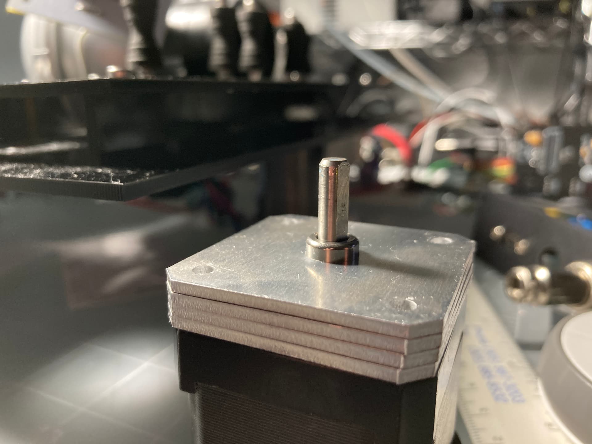

These two changes addressed one of the highest contributors of the unexpected movement.
Tension Sensors
The project uses dancing guides, pulled by silicon rubber, on a potentiometer axle. The original potentiometers were of lesser quality, the shafts also started to show signs of play.
A new quality part sourced as replacement had a slightly different knurl in the shaft, and while updating the “hat” it was a good opportunity to set the silicon rubber attachment point at a slight angle.
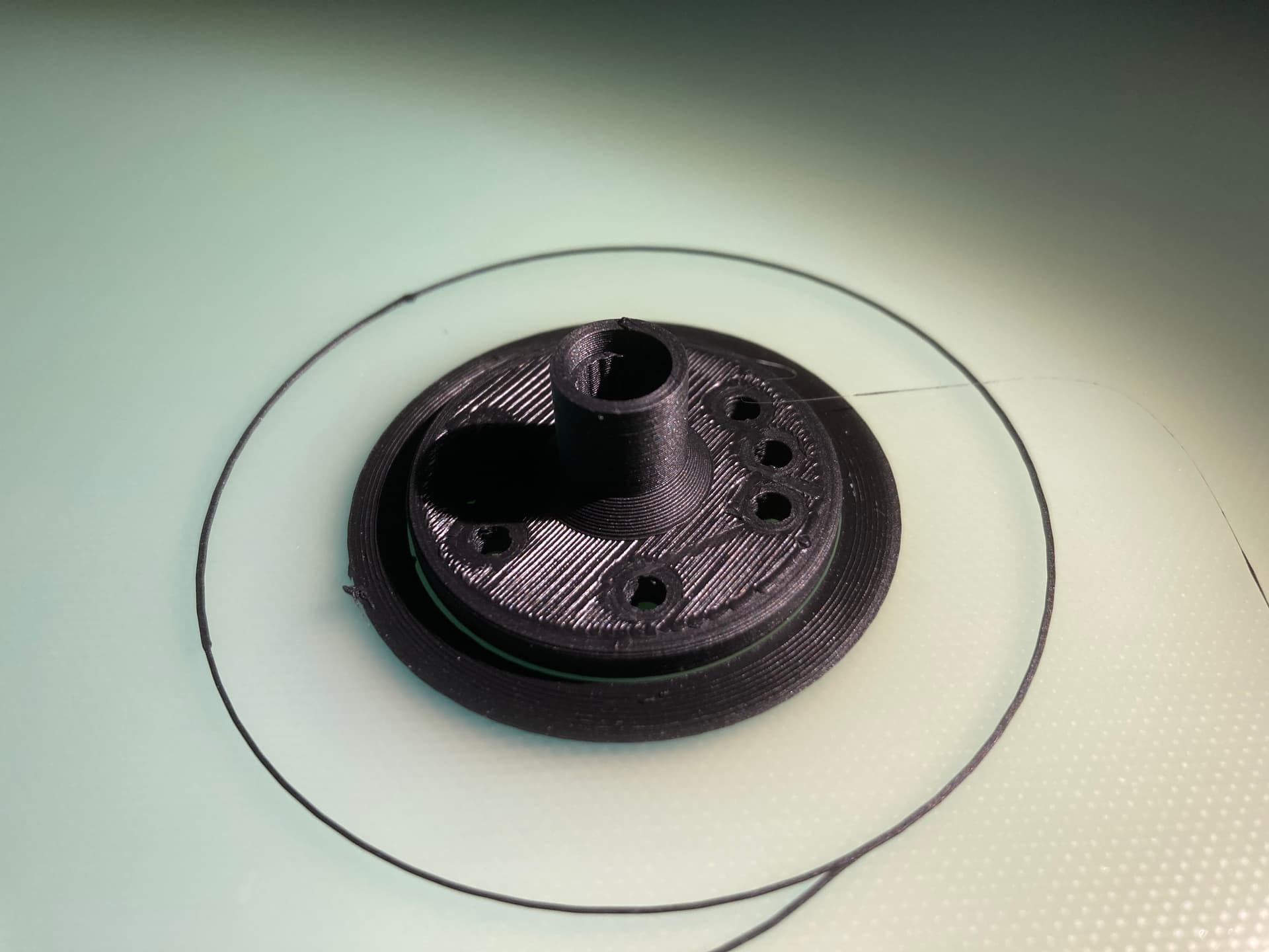
Replacing the potentiometers improved significantly the quality of the readings, the mechanical stability, and had a small incremental improvement in the unexpected film movement results.
Additionally -and related- improving the stability of the PICO ADC voltage reference was just as significant, if not more. In addition to prior improvements to the ADC (removing R7 on the PICO), the PICO now has a better reference.
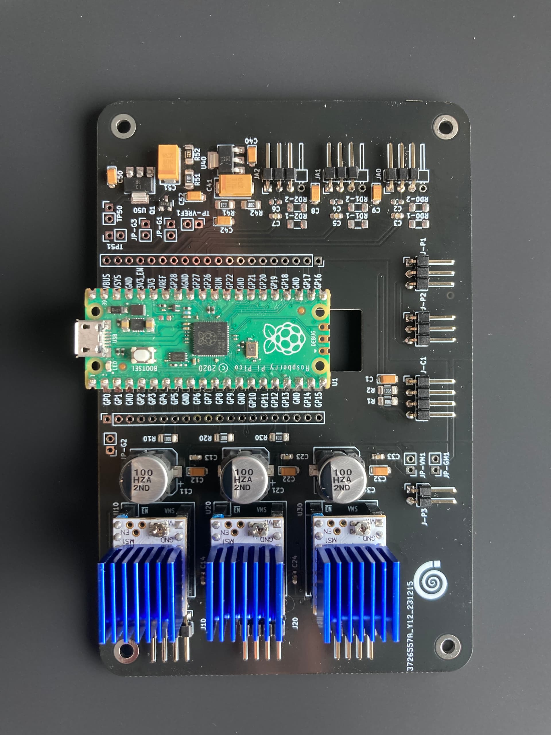
PCBs
The PCBs designed late 2023 were ordered and built. And as part of building these, it was necessary to rig an SMD soldering plate, which actually ended up being an SMD soldering toaster.

The project LED driver had being previously redesigned to use mostly SMD components, and provide the flexibility to accommodate future LED configurations.

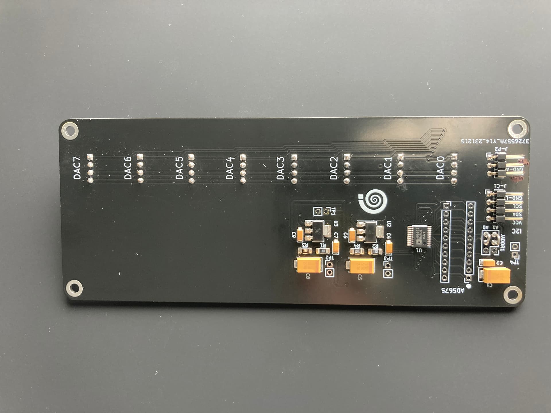
This setup results in a 16 bit Digital control of the LED intensity on a constant current driver configuration.
The MCU PCB holds the PICO, three stepper drivers controlled via UART, the ADC reference and conditioning, and the output to control the DAC.
F-Code Protocolling!
I just made that up, but in order to keep sanity on the transport control, a simple Protocol was created to provide/get anything that goes through the PICO, and between the PICO Cores… see next.
PICO C Code
Another finding in the search for the unexpected movement result was that Core 1 of the PICO services also the USB serial communications, and in doing so, it spuriously changes the timing of the ADC reading. For more details, see the exchange in the Raspberry Forum. https://forums.raspberrypi.com/viewtopic.php?p=2221107#p2221107
With the ADC providing the tension reading, and with the need for smaller micro steps, the requirement was cycles in the tens of microseconds, and this find was very significant. The project does not use the PIO, in part, to maintain linear motor control, and timely and accurate cycles are necessary.
Given that the PICO does have two cores, the time critical functions were then moved to the Core 1, leaving Core 0 to handles slower/non-critical items such as USB communications, and LED I2C communications. Time critical items are now solely on Core 1, including ADC (tension reading) and Stepper control.
Another finding was that the PICO execution speeds improve greatly if the code is run in RAM. A significant improvement on the time-critical functions was realized by using __time_critical_func() to instruct the compiler to load these functions into, and ran them, directly from RAM.
Spurious ADC timing was yet another significant contributor to odd/spurious unexpected movement results.
3D Printing
Somewhere in the past year, a beaten Ender 3 needed an overhaul and a foster home, and that facilitated crossing out some items, such as the redesign of the tension hats, mounting for the PCBs, and hoods between the sphere and the lens.
And…
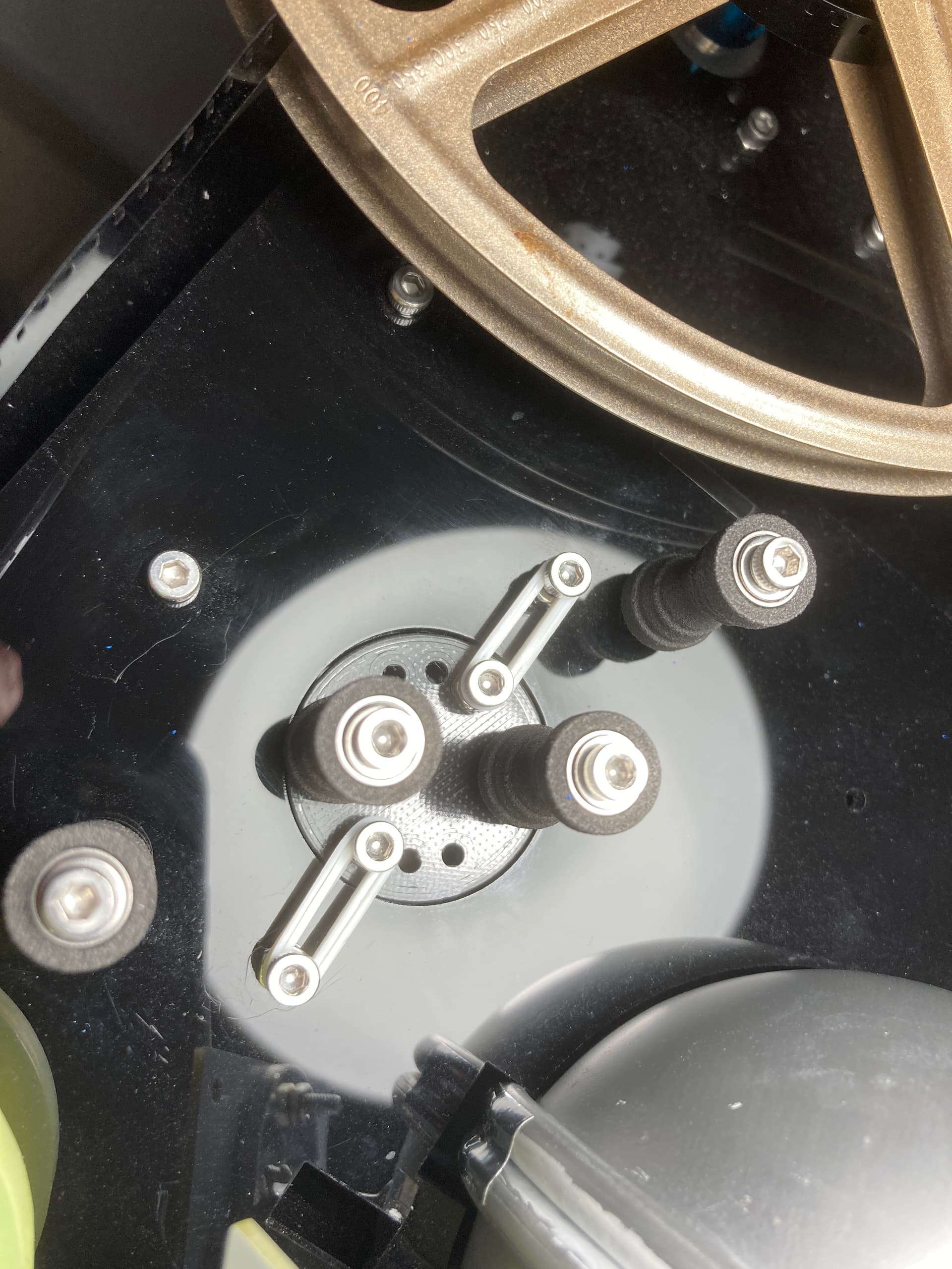
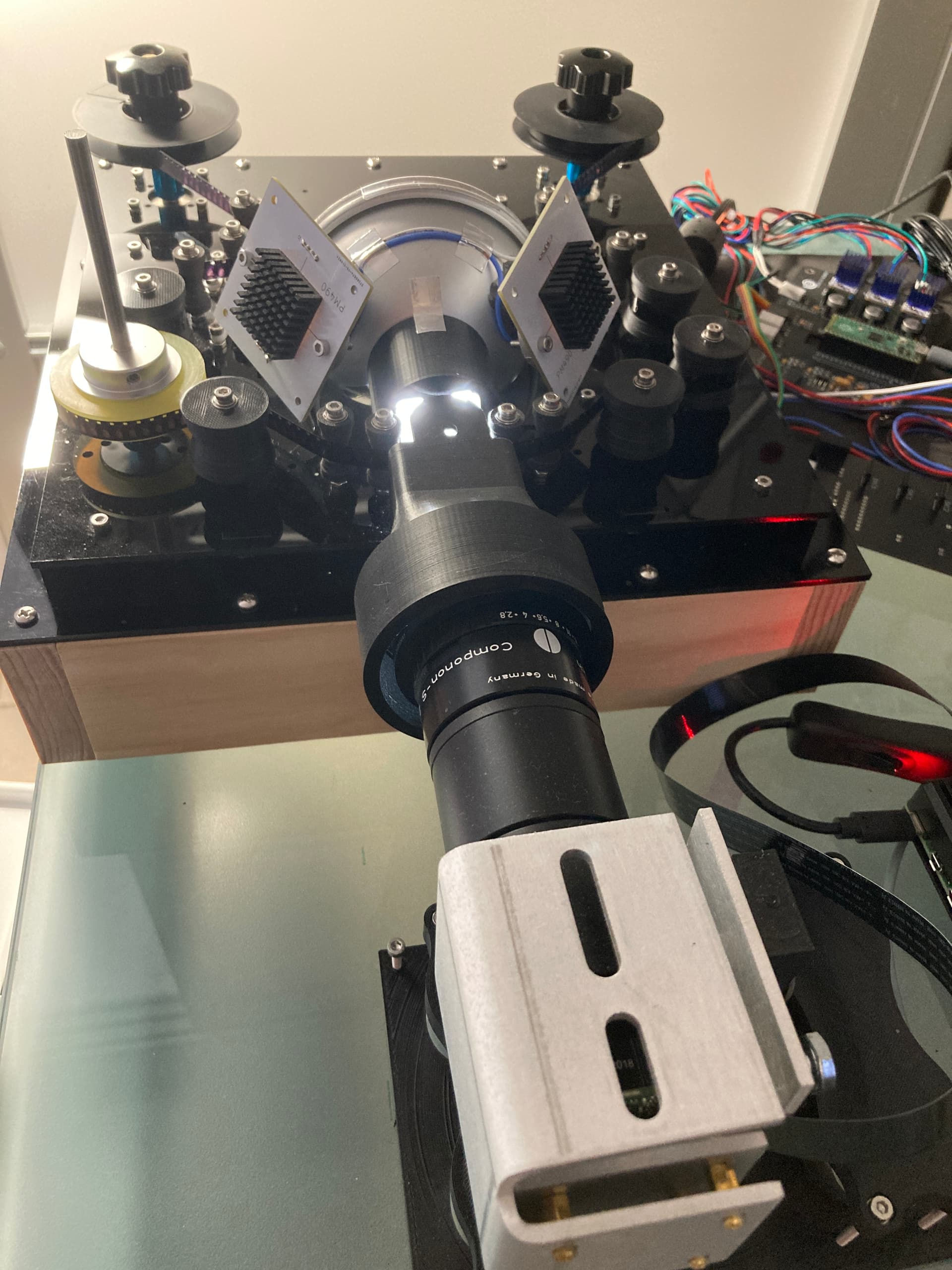
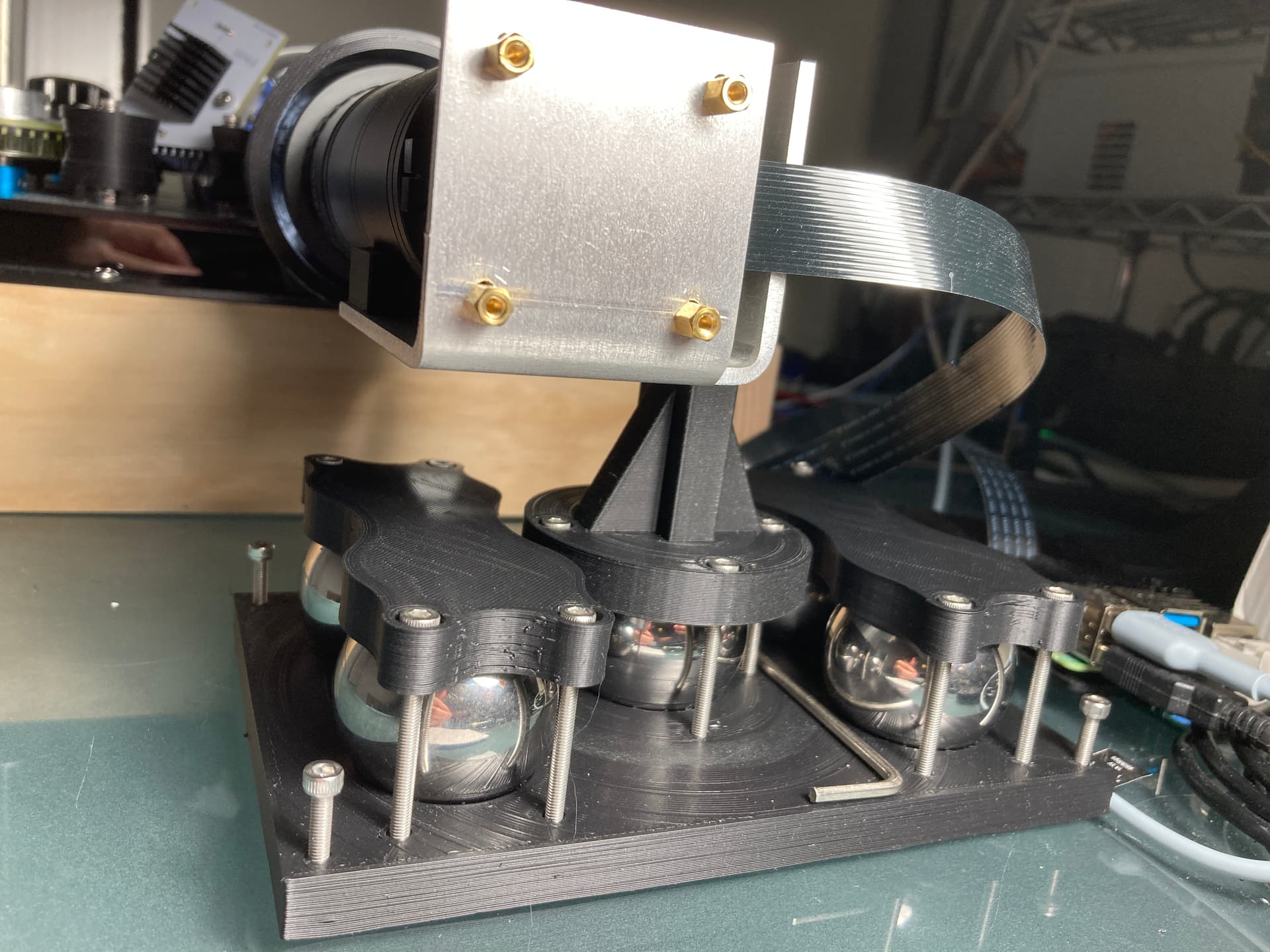
The Camera Mount
Anyone working with 8mm knows that one’s scanner is a unique vibration seeking device. Regardless of the nice aluminum custom piece (previous postings), the camera stand was less than ideal.
On the other hand, 3D printed parts were too light to keep everything from vibrating or moving.
Looking for ways to make the camera stand as heavy as practical, 38mm steel bearing balls were affordable and small.
A widely used camera mount is the ball head… so another solution was using one of the steel bearing balls as a ball head for the camera arm, with M3 thread screws providing very fine adjustment for the the camera roll and pitch axes. The bearing balls came in pack of 5, the other 4 were use to increase the weight of the base.
Raspberry Pi (4B) and HQ
It was finally time to learn the particulars of the HQ sensor, Raspberry Pi, Python, and some kind of minimal work reference GUI to integrate the existing modules into a workable scanner.
A key design constrain has been the ability to scan16mm, Standard 8, and Super 8, with minimal or no transport changes. In order to do so, the transport is sprocket-less, with detection and feedback of the film position extracted from the sensor image.
The HQ and Raspberry Pi 4 is a less than ideal combination for this purpose: limited processing power, and limitations of frame-rate at higher resolutions.
With the mind-frame of working with separate cores with the PICO, it was natural to reduce the overhead of processes launching across different cores, by associating processing hungry or time consuming items to a specific core.
To that effect, the camera loop would run on core 3, the raw pipeline on core 2, and transport control and file-saving on core 1. The RPi4 is running headless, so there is a bit of overhead on the VNC, the GUI, and the waveform monitor, but these processes were left without a specific core association.
Rawer than Raw
Capturing a raw array (not the same as capturing a raw/DNG file) provided an alternative to stabilize the capture to the sprocket hole horizontal edge and the film vertical edge, a work around to the challenges and limitations of the transport. The work is in itself a deep rabbit hole, and this post provides much of the journey. Raspberry HQ - capturing or extracting raw values
The result is the RGB values binned (2032x1520 with R/B at 12bit and G at 13bit depth) of the raw capture, and after cropping results an uncompressed TIFF (1900x1300). As described in the posting referenced, the TIFF is a representation of the sensor values, and requires a color processing pipeline that is performed in Davinci Resolve.
A process to create a synthetic color from the active area of the film was used to greatly simplify balancing of the resulting TIFF.
Scanning Run
A good reality check was to scan 35 reels (50 ft. each) of Super 8.
At present, the RPi 4 saves via Ethernet to a NAS, and it does so at about 24 frames per minute, about two and a half hours per reel. Certainly in keeping with the project name!
None of these films I had scanned previously, these belong to a family member. Post capturing processing was done using the synthetic target and color processing pipeline in Davinci Resolve. No image stabilization or noise reduction was performed in post.
The deliverables look fantastic, here as a framegrab of the final MP4 video (3840x2160).

More work
Much clean up is needed in the existing code, and there are some areas that need additional work, including:
-
Completing F-Code commands and improvements on the PICO firmware.
-
GUI for operational settings (light intensity/film format).
-
Sprocket detection/capture stabilization improvements.
Development tools for special cases
There is also one Standard 8 film that for unknown reasons virtually has no red component. I am uncertain if it is the result of exposure, development or both. This particular film has a scene that has a unique cultural value.
With the goal of making the best of challenging conditions on the scene/film, the plan is also to improve the modularity of the capture code to allow each color channel to be captured at different light setting. Additionally to have the option to implement individual channel stacking and provide a lower noise and increased bit depth separately for R, G, and B.
Needless to say, this planned mode will trade much capture time for what I hope would be noticeable scanning improvements for film with special conditions.
It worth highlighting that since the scanner is now running without gears, it is quite easy to position and scan a single scene in the middle of the film. So the intention is to do separate exposure and stacking for only the content that requires it or is worth the extra time and effort.
For now… That’s all folks!