Frame-by-Frame / Stepper Control / Arduino / DigicamControl

I would like to document the use of DigicamControl as bridge for a simple frame-by-frame capture workflow. This implementation also uses a NEMA17 stepper to advance the film.

The combination of Arduino/DigicamControl greatly simplify the camera control. Another advantage is opening up the range of cameras that can be easily control with Arduino, and using the computer storage for large-size captures, including raw.

My setup is a bit more complicated that the above, but while I get to the point that I document the scanner details thought that sharing the arduino code, wiring to the stepper, and implementation with DigicamControl would help greatly those who are Frankenstein-ing a projector or are in need to work with a stepper to move film.
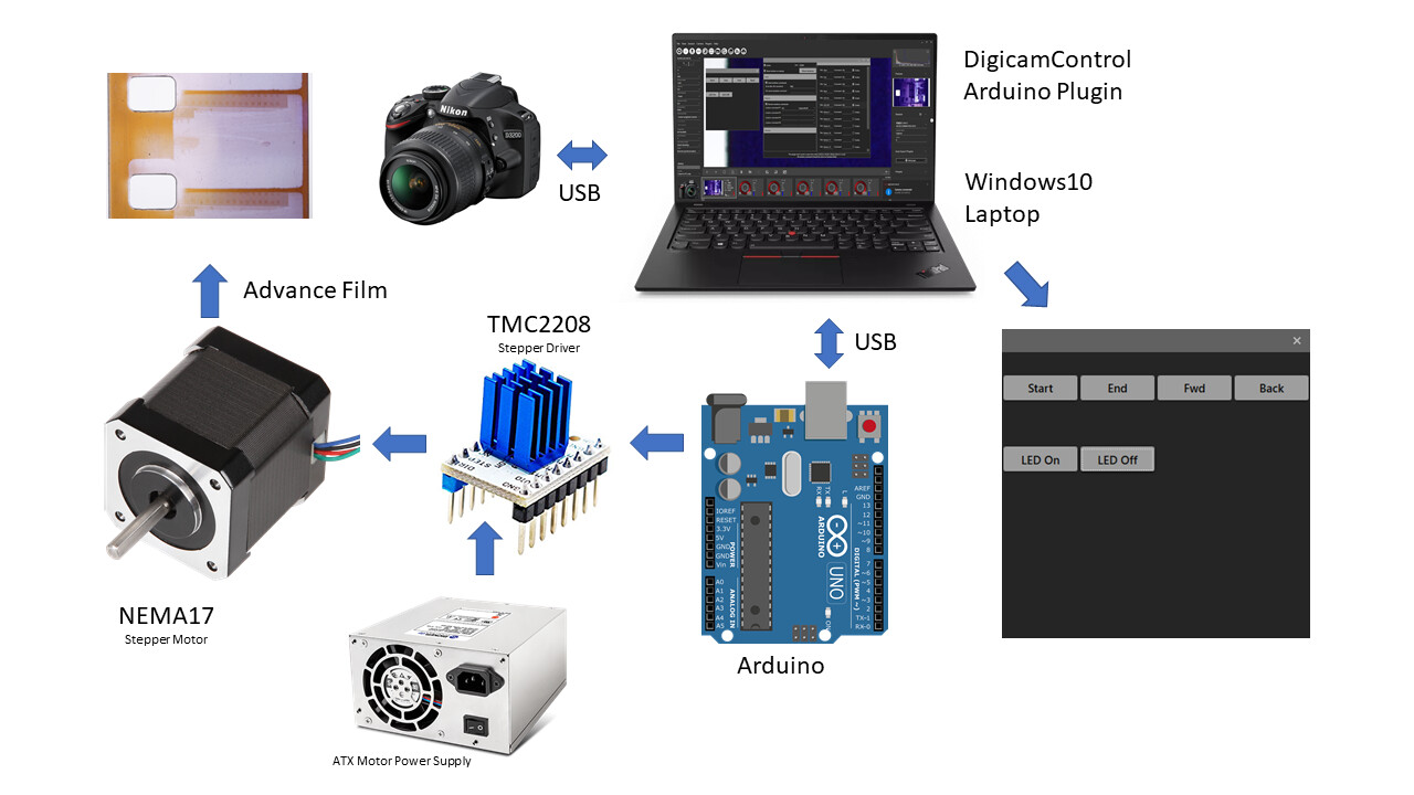
Setup Diagram

Repository
I will keep the files in the framebyframe github and improve/update/add as needed. A pdf with additional information on the setup is part of the repository.
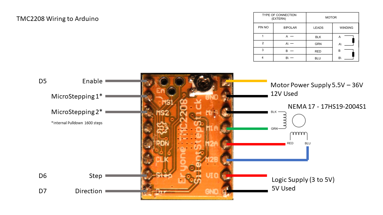
Stepper Driver
The Stepper is controlled with the TMC2208, which provides 1600 steps by turn capability. It makes the motor run very quietly. The wiring is quite simple. There are also Arduino shields for 3D printing that already have the socket for these controllers. For these motors to run well, having abundant power is the key. I am using a recycled ATX power supply 12V to power the driver/motor.

Stepper linear speed
Additionally, I implemented linear speed control (asceleration/descelaration) with reference on the paper by Atmel on the subject. The advantage is to be able to have faster turns, and keep the stepper extremely quiet.
This implementation does not use interrupts, which makes it a bit easier for those starting with Arduino.

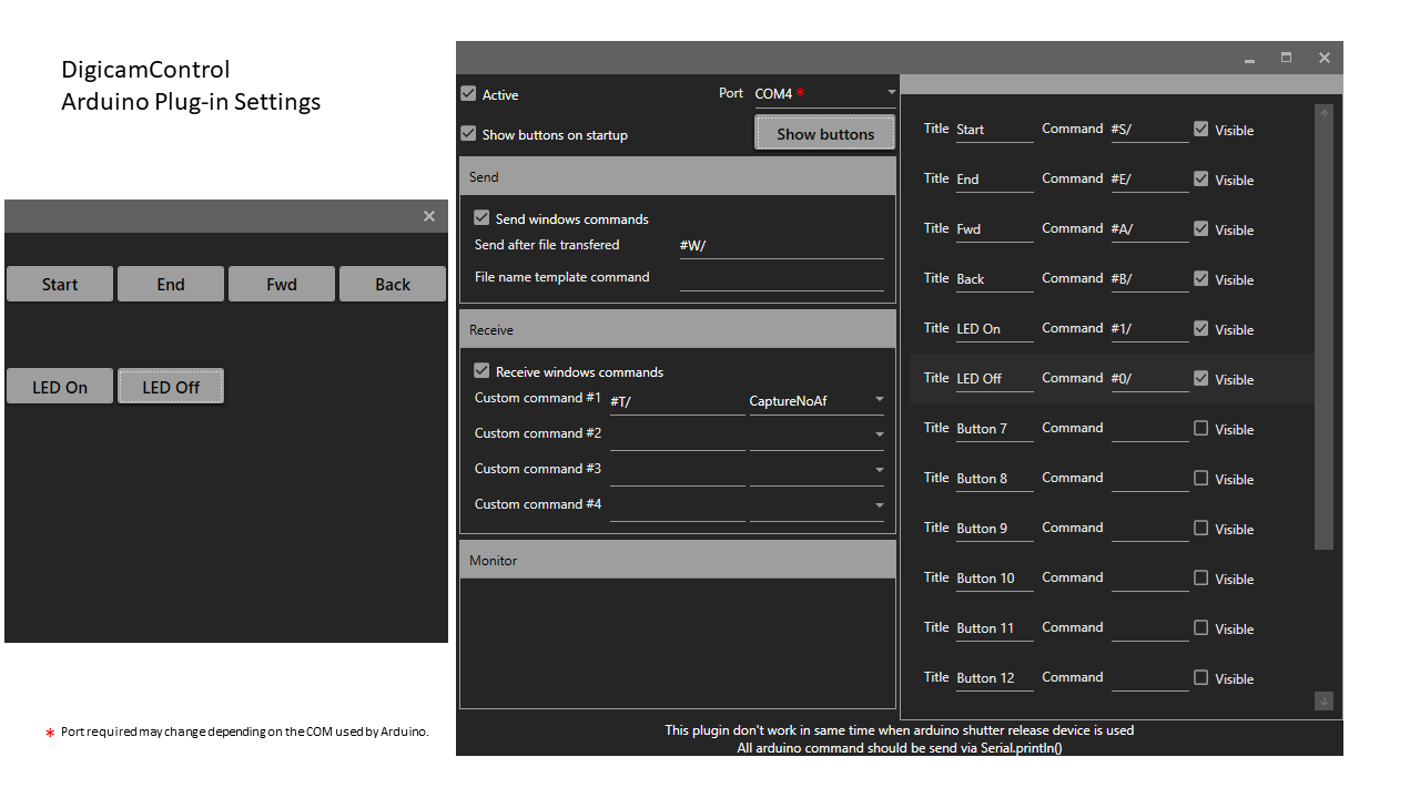
DigicamControl + Arduino
DigicamControl (DCC) has an Arduino plugin. This software implements a sequence whereby the Arduino triggers a capture, and the store of the file triggers the Arduino to advance the film/turn the stepper. Additionally it implement other commands (Forward/Backward/LED On/LED Off). There are useful to test the mechanics and examples of implementation of additional commands that may be required by your built.

In summary, if you have a project where you need to control the transport with the stepper, take a picture with a DSLR or other camera that can be connected via USB to DigicamControl, this will greatly help you get going. In this case one turn = one frame, feel free to adjust the Arduino to fit your needs.

Hope this is helpful to all.

@fa001 Fred, sorry for the long wait, you requested the arduino code for my project a while back.
@Marco_Leoncino Marco, this should get you started.

4 Likes

@PM490, your project looks amazing, I’m looking forward to seeing more of it!

May I ask what specs your power supply (power) and stepper motor (amps/phase) have? Have you had any issues with the stepper motor skipping steps?

I’ve actually also converted an old projector where I’ve placed a stepper motor in place of the original motor (just like the Scott Schiller scanner). My motor is skipping steps / getting stuck mid-movement every few hundred frames or so, despite running in full-step mode. It usually comes free by itself eventually. I originally had a much smaller and weaker stepper motor installed and chose a power supply to go with it. I then didn’t upgrade the power supply, mainly because I figured “it’ll do for now”, when I had to replace the motor. Now I’ve seen your remark that abundant power is the key, I’m quite sure that the lack of power is probably the most likely cause of my problems.

For reference, so people reading this can avoid making the same mistake: I’m using this NEMA 17 stepper motor at 12 V with 1.5 A/phase. The motor is controller using an A4988 driver and hardware-timed PWM via the pigpio library on Raspberry Pi. I’m using a generic 12V 24W power supply that also supplies a 3W LED in addition to the stepper motor.

Hi @jankaiser,

My machine is also based on an old modified projector.

I had never used a stepper motor, but from the get-go I decided on a large motor.

This is the motor -driver set that I am using:

https://es.aliexpress.com/item/4000340898079.html?spm=a2g0o.search0304.0.0.e0cd616fOObbzp&algo_pvid=56d964f8-188c-4a21-b060-984918a78c7e&algo_exp_id=56d964f8-188c-4a21-b060-984918a78c7e-13

I have reason to be very satisfied. Despite the considerable size of the motor and the driver that came with it, there was enough room inside the original case to house them.

At first, the motor-projector mechanical coupling was done with a toothed wheel on the projector shaft and a pinion on the motor shaft. With this mounting, two full turns of the motor shaft were required to advance a single frame.

Later I decided to mount the gear on the motor shaft and the pinion on the projector shaft. With this new assembly, the transport speed of the film was multiplied by four. It only takes half a turn of the motor shaft to advance one frame.
The motor works at the maximum resolution of 32 microsteps per step, the operation is very smooth, silent and precise, although of course slower than working at full step.

It has never given me any problems. The software that controls motor movement is about the only thing that I have never modified from the beginning.

As a power supply I use a 12 V source recovered from an old analog flat screen TV, which complies perfectly.

By the way, your optical system served me as a model for the one I have now in operation, with very good results. Thanks for sharing.

Regards.

1 Like

@jankaiser thank you for the kind words. I was looking at your motor specs and they are actually very similar to the one I use.
I am no expert on steppers, full disclosure this is the first project using these. From what I see your motor actually has a lower rotor inertia, in theory that spec is better. It does show a lower holding torque, and I did not find a torque curve in the datasheet to compare.
If the stepper is strong enough to do 100 frames, it is worth taking a look at what is happening in the projector when starts skipping steps. For example, is there something in the film that makes it harder for the projector mechanics to move (like a splicer).
I am familiar with Scott Schiller project through his videos and the parts I use are actually from the same projector make and model. I do not drive the entire projector, only the gate which is connected directly through an axle coupler with the stepper. So it would not be fair to make parallel on the motors given the difference in the setup.
I would make a few suggestions to check, forgive me if you already thought of these.

  • clean/lubricate the projector mechanics - In my case, old grease was making it harder for things to move, it worked much better after.
  • Change the step-to-step time. I ran some tests with my stepper, without load, and figured out the fastest it would run without skipping steps. Then use a safe headroom. However it is running close, so if there is an issue that creates additional load on the mechanics it will sleep. For example, if the film gate was too tight.
  • If you are not doing it already, consider using an ramp to star/end the turn. The Atmel reference in the post. That would help if the steps are being skipped at the start of the turn. To aid with the inertia the algorithm spaces the steps in the beginning over longer time, making a speed ramp, and it does the same.
  • Verify the calibration of the A4988. I went through the process with the TMC2208 to set the appropriate current levels for the motor.

All of the above are improvements. I think you are on the right track checking on power, and suggest before you change the motor try a power supply with a bit more current availability. Sounds like you are running at capacity on yours and the steppers when challenged by torque will demand additional current and skip if the driver/power supply is unable to provide.

Lastly the specs of the power supply I use, it is an ATX recycled from an old computer, it is rated for 13A on the 12V, and I am only using the 12V for the stepper. The Model is ATX1125BTA, and I use this adapter run it.
One more thing. If you are using a belt (which is not my case) make sure the gear ratio between the diameter at the motor and at the projector work to your advantage. I noticed in Scott Schiller that he used a larger one at the motor.
Lastly if all of the above fails and you need to buy a new motor, consider a gear stepper for more torque. Hope these help, and take it one step at the time!

1 Like

@PM490
I’ve finished my Raspberry based project but yes the PC/Only, USB Camera + Digicamcontrol + stepper motor solution is definitely worth considering. I had already seen a number of such solutions based on a trigger I think. The Digicamcontrol arduino plugin for motor control is more rich in possibilities

@jankaiser
I have no problem with my NEMA 17 stepper. Mine is powered and 36V 1.5A. As Scott Schiller and Manuel_Angel I recommend a TB6600 based controller which has several advantages and is configurable (steps and intensity) by switches. The pigpio library is really very convenient to use. If you look at my code you can see how to use pigpio “wave chains” to implement a soft start (less sophisticated than the one described in the Atmel paper)

1 Like

Thank you @dgalland my intention on sharing is to provide alternatives and to provide a simple test bed too for those just starting. Needless to say that the arduino plugin in DCC communicates via a USB Serial Port on the PC. Anything that can be turned into a USB-Serial port can also communicate with DCC in the same manner.

@jankaiser a good point on the suggestion by @dgalland: you may also experiment with higher voltage power supply for the motor, since the A4498 supports up to 35V. If the issue is transient power availability that may give you additional headroom.

@jankaiser - that is probably the main difference. From my experience, running NEMA-17 steppers with 12 V is the absolute minimum. If you increase the voltage, for example to 24 V, you should see an improvement in performance.

Important point: be sure to set the maximum current for your stepper - that is usually done with a small potentiometer on the stepper driver’s board. There should be a formula from your stepper driver’s manufacturer which relates the voltage you can measure between two pins on the board (between 0 and about 2 V) to the maximum current the stepper driver will supply to the stepper motor. Have a look at the section " Current limiting" on the Pololu A4988 page for some further details (be sure to watch the video until the end - the presenter discusses also the actual motor currents).

Again, from my experience, the larger the voltage you are operating the stepper driver with, the better the performance will be (24 V works usually better than 12 V for me). But make sure that the maximal current is appropriate for your stepper (via the potentiometer setting) and the driver board as well. I think A4988 should not operate with currents larger 2 A or so. Certainly, it can only go to a maximum operating voltage of 35 V, so a 36 V supply is “out-of-spec”. Also, check the temperature of your stepper motor and driver during operation. You might not want to go up to the limits of your stepper motor - try 70% of what is claimed as current in your data sheet and slowly increase from there if the performance is not sufficient. During all that, check the temperature of your stepper motor/driver after about 10 minutes of operation - it should certainly not exceed the specs.

2 Likes

@jankaiser Maybe there is also a software problem?We agree that we send a continuous PWM signal. Using the pigpio library is already a very good thing since the control of the motor is done in a daemon independent of the application. But the PWM loop must be also in the daemon and not in the Python application, so for a better performance you have to use the “wawe chains” of pigpio

First of all, thank you all for your very helpful input!

I finally got around to running some more tests in the past few days and I seem to have solved my problem. The short answer is that pigpio's wave chains seem to have worked for me. I have run my machine for almost 20k frames with only one hiccup. The latter wasn’t the stepper motor, but instead the belt slipping (whole other story).

For completeness, here is the long answer – including the setup I’m using:

My stepper motor replaces the original DC motor in an old projector. It is connected to the main aperture wheel and thereby the main shaft of the projector’s mechanism by a belt. The pulley mounted to motor’s shaft is quite a bit smaller than the “pulley part” of the aperture wheel, i.e. the gearing is in the motor’s favour. Note that as the projector mechanism goes through its action, there is a strong spike in resistance about halfway through the action when the shuttle is pushed down against a spring that pushes it back up a moment later.

When I originally put my machine together, I actually used the output function RPi.GPIO Python package and some sleeping in between to drive the stepper motor – not a good idea as most of you probably saw faster than I did :upside_down_face:. Don’t do this! At least in my case, the motor ran audibly badly and didn’t come close to its actual performance. This is probably the most “softwary” of software PWM one can implement on the Pi.

The RPi.GPIO package also offers a specialised PWM implementation. This is probably better than the crude implementation above, but it is also software-based and therefore also subject to potentially inaccurate timing.

Therefore, I went straight to the pigpio package which offers much more accurate hardware-timed PWM, the wave chains mentioned by @dgalland (I believe also hardware-timed), as well as actual hardware PWM. When I posted on this thread, I was using hardware-timed PWM of pigpio. This has the stepper motor run audibly more smoothly but did not solve the problem of it getting stuck in the high resistance section of the action. At this point, I figured I have a hardware problem and that’s why I asked for the power supply specs.

I have since switched to the wave chains. I believe they are hardware-timed in the same way that hardware-timed PWM is, but more importantly they make accelerating the motor rather convenient. As a result, I can run the motor a good bit faster and, while the speed should technically result in decreased torque, I believe that in this specific case it gets some momentum going in the mechanism that ultimately helps overcome the brief spike in resistance. Think of the aperture wheel acting pretty much like a flywheel. The improved PWM timing helps achieve a faster speed and thereby larger momentum, as well as also preserve that momentum because the motor continues to move smoothly. As an added bonus, the faster motor increases the frame rate slightly and makes the entire machine run more quietly.

So in conclusion, wave chains are definitely the implementation of choice for driving stepper motors on the Pi.

Note that, while I haven’t changed the power supply (yet), the specs of mine are definitely not ideal and as has been proposed above, a higher voltage and probably a little more power would do the motor good.

2 Likes

These discussions and the OP at the top of this thread have me thinking that it might be a useful exercise to come up with recommended builds for folks who don’t want to endlessly tinker and just want to build a machine. Or even a few different kinds. It would be most helpful if the guide is opinionated in its recommendations so as not to confuse a newcomer with a bunch of options. We can, however, include “footnotes” throughout that point to alternatives where appropriate.

What do you think?

  • Projector-Based

    • what to look for in a projector
    • what hardware to buy, what specs are important, etc
    • installation
    • software/scripts
    • cameras/lenses
  • DIY Scanning Machine

    • can rely on 3D-printed parts
    • only uses off-the-shelf components for the build (no custom milled/lathed/cnc’d parts)
    • uses entry-level electronics, as close to “plug-and-play” as possible
    • ideally, no soldering required, but if we have to we can provide the files and they can order the PCB from a manufacturer or ask a friend to do it for them.
  • User-designed kits

    • promote builds from this forum
    • if the designer is unable/unwilling to provide parts and/or documentation then we could do it for them
    • if the design is unable/unwilling to take care of fabrication of parts, shipping, and payment then we would have to setup a store. Proceeds would go to the original designer, and a percentage would go towards supporting the community (paying for the forums servers, maybe even a “lab test” account people could ask to access if they have a test that requires materials and whose results would benefit the majority of the community…)

In all cases, tutorial videos and well-written, clear documentation in multiple languages would be ideal.

That’s a lot. I got excited. All feedback welcome.

3 Likes

Your plan is exactly what I was looking for but did not find so I did post some starting questions. I may after my build decide to try and improve the system where I can then start to contribute to the newbies.

1 Like

We would love that. Thanks for starting the discussion! An easy starting place for scanner enthusiasts is long overdue.

I love the idea! That is something I was actually hoping for when I first stumbled across Kinograph way back when.

I think the perfect thing to have would be a finished machine design, where people have to just get some parts 3D printed and buy others that are easy to find (e.g. Raspberry Pi, Arduino, Stepper Motor, Pi HQ Cam). This scanner could then be assembled and used by anyone according to instructions without requiring much technical knowledge. This would include hardware as well as software. Think an 8mm Kinograph that could live on GitHub and could even survive without much active support like someone shipping parts.

Obviously, the above idea would require quite a bit of development and is simply not available at this time. Therefore, I would recommend converting a projector to anyone starting out. There are projects like @Manuel_Angel’s and the one by Scott Schiller that are somehwhat well document and easy to follow. At the same time, some people like @Manuel_Angel have also been so kind and published their software. I, too, hope to fix the last kinks of my own system and publish both software and details on how I have built it soon.

So maybe a good guide to start building your own 8mm scanner today would contain:

  • General projector conversion instructions
    • Specific conversion instructions/examples from people who have converted certain models
    • A short list of projector models members of the forum can recommend for conversion as well as general criteria to look out for when choosing a projector
  • References to software projects that can be used to drive a converted projector with little to no modifications to be used on someone’s own project
3 Likes

Thanks for the feedback @jankaiser. I agree this is a worthy endeavor and would like to see it come together. I will send out an email and make an announcement along with my next monthly update. In it, I will ask for volunteers to form a group that can review existing solutions in each category and make recommendations. These will change over time, but at least that will give newcomers something to start with instead of having to sift through the forums.

Any other ideas on how to move the idea forward are welcome!

Introducing a quick video of the frame-by-frame project described above and sharing a new youtube channel for future work on the project.

1 Like