Continuing with the SnailScan project, here is a quick status report.
One of the recurrent items in the forum, is the control of light/LEDs. I previously posted a constant current design that I used on the projector-parts based scanner. The old design used a PWM control signal, which was converted to a DC voltage, and change the LED current. For clarity: the LED current was constant, not PWM. The conversion from PWM to DC uses a filter, which introduces a reaction time. The better and more stable the DC, the longer the reaction to change current at the LEDs. A trade off to use a simple control line, which as the original posting mentions, takes advantages of workarounds to have 16 bit control. For the application, it was manageable, but there was certainly room for improvement.
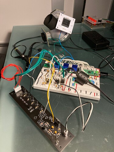
The protoboard of the electronics for the new build, consist of:
- Raspberry Pico
- Three TMC Stepper Drivers (supply, pickup, and capstan).
- I2C DAC (8 outputs, 16 bit each)
- DAC to LED Driver Buffer (only one).
- Voltage regulators.
- The sphere with 3 LED Boards, each Board has 4 LEDs, each LED runs at 3/4W max (for about 9W max total).
The black PCB is the old driver, used in the proto-boarding for the current mirror transistors and the voltage regulator.
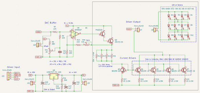
This is the schematic of the improved LED driver.
The gray box are shared components with the old design. Whatever current is set at Q3, will be mirrored by Q4, Q5, Q6, and Q7. If Q3 is sensing 75 mA, the four transistor in the mirror configuration will total 300mA.
Using the same configuration, I would like to share some of the improvements.
Two Supplies
The new design uses two voltage sources VL = 15V, and VLED = 32V (these LEDs have a Vf of 9V, so having a cascade of 3 requires voltage higher than 27V and must include headroom for the transistor Vce).
Being a linear design, the various configurations and specifications of LED require different voltages for the LEDs. But the driver does not have to be linked to that higher voltage, since the interface with the drivers is current driven.
It makes everything cooler, since the parallel resistors can be driven by the same current, but with a lower voltage… less heat.
DAC to Mirror
In the old design, the base of the darlington-pair was driven by the DC generated by low-pass filtering the PWM.
In the new design, instead, an OpAmp configured as non-inverter amplifier, and buffered by the same darlington-pair prior, now takes the DC output of the DAC (0 to 5 V) and conditions it to the desired current level needed at the current mirror.
Flexibility
This configuration can be adapted to different ranges in DAC, different LED voltage requirements, and different currents, only by changing values of resistors.
The same board can be used for widely different LED requirements too, from the extreme represented above (large Vf with large current).
Repeatability
A board for the components of the schematic, times the number of colors (up to 8 for the DAC), and one can put together a multi-spectrum-stop-motion scanner. This part is solved.
Limitations
Because of heat management at the LEDs inside the sphere, this is not intended to work continuously-on while at full intensity. Also it is likely that all the available light will not be necessary, it is a bit of an overkill, but I am taking advantage of the prior design/components. Reducing the light output during the movement period is sufficient to cool it off.
Next steps
Light is the one item of the scanner that I have dedicated the most time, and iterations. I am pleased with bringing it to this level, and hope that sharing these findings help everyone in their journey.
Note: experience is what you get, when you don’t get what you want!
No amount or ability to control light can make the film move! My next challenge is to assemble a new transport with the experience of the earlier failures.
Coming up…
- The transport design is getting there, and I hope to send the parts out for laser-cutting in the next few weeks.
- Two PCBs will be designed to assemble the electronics. The PICO, 8-channel DAC, 3-stepper drivers, in one. The LED Driver only (schematic above) will be the second PCB.
- Testing the assembled components (transport and electronics).
- Finalizing programming of the PICO to receive USB-Serial commands for the transport/light control.

