Sharing failure - Time Of Flight Sensor and sprocket-less transport

I have been working on my first transport.

To follow the steps of Sasquatch… and great name for scanners by @friolator, I will affectionally call this project Snailscan… it is a very slow moving animal, with no feet… analogy for a slow moving scanner without sprockets.

My first scanner used projector parts. Adding to the challenge was/is to build a transport without any projector parts.

The goal: to design a low-cost scanner for 8mm and 16mm, with the quality and shutter limitations of the Raspberry Pi HQ camera, using the most off-the-shelf components, no projector parts, and make the proof of concept repeatable.

Having a camera with a rolling shutter = stop-motion transport.

For my first project, I was able to have great control of a stepper, and decided to try to direct-drive a supply and take-up stepper. To do so, it was necessary to sense how much film is in each reel, since the number of steps to move each/both reels -the corresponding amount of one frame- will vary with the diameter of the spool.

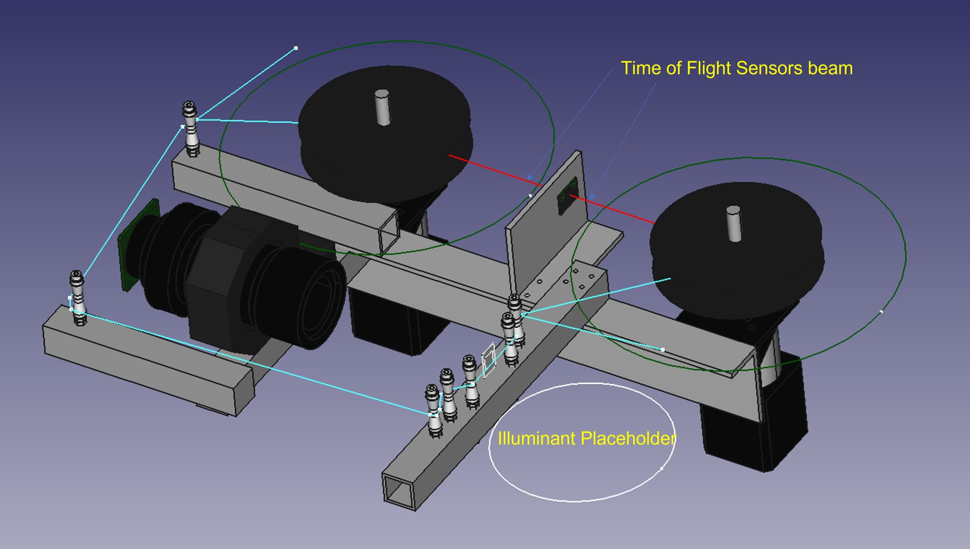
How to sense the size of the spools in a novel way? I was puzzled by the prospect of the Time-of-Flight sensors (ToF), which are known for accurate short range distance measurements. The one used was the ST Microelectronics VL6180X, for convenience, the Pololu Sensor Carrier VL6180X. A similar is available from Adafruit.

To manage the steppers and the sensors, the transport would be controlled by a Raspberry Pico.

I think it is important to use the forums to share our successes, but equally important is to share failures to collectively learn and adapt.

There are libraries for the VL6180X by Adafruit, Pololu, and STMicroelectronics. But for simplicity and flexibility, decided to write couple of functions (init and single shot range function). The sensors worked well measuring distance to many materials, and to a flat piece of film, but when measuring inside the reel, the measurements became unreliable. Even in the best conditions, these sensors are not very precise. This video elaborates. Tried a Kalman filter with some improvement, but the measurements under the conditions were inaccurate.

ToF sensors have interesting potential, but the results for measuring the size of the spool with ToF were not very reliable. That’s the initial failure to share.

Surprisingly though, the geared stepper motor was a great success. Even when used open-loop without any sensors, for a short segment with a fix measured diameter of the spools, these were able to move fairly accurately close to a frame.

Here is a quick video of the movement, supply spool full and take-up spool almost empty.

The next step for SnailScan is to figure the best use these. There is a lot of good ideas in Denis Carl’s Gugusse Roller project, which uses roller board wheel driven by stepper as a capstan, great project.

Not yet giving up on the direct driving the reels… still thinking on the best approach for the next iteration.

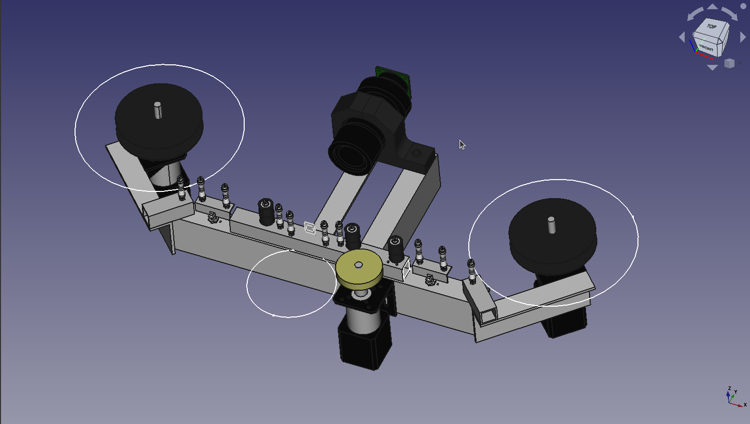
Here is how the SnailScanner V0.1 looks.

In summary, what worked and what didn’t

  • First time using the Pico, and I am trilled. Having that speed for five bucks is unbeatable. Building a transport controlled by the Pico driven by the Raspberry Pi (for HQ cameras) or by any other computer (for other cameras) is definitely the SnailScan way forward.
  • Gear steppers worked great, specially when using the TM2208 and applying linear acceleration, both which I used on the first scanner, and reused with the SnailScan tests.
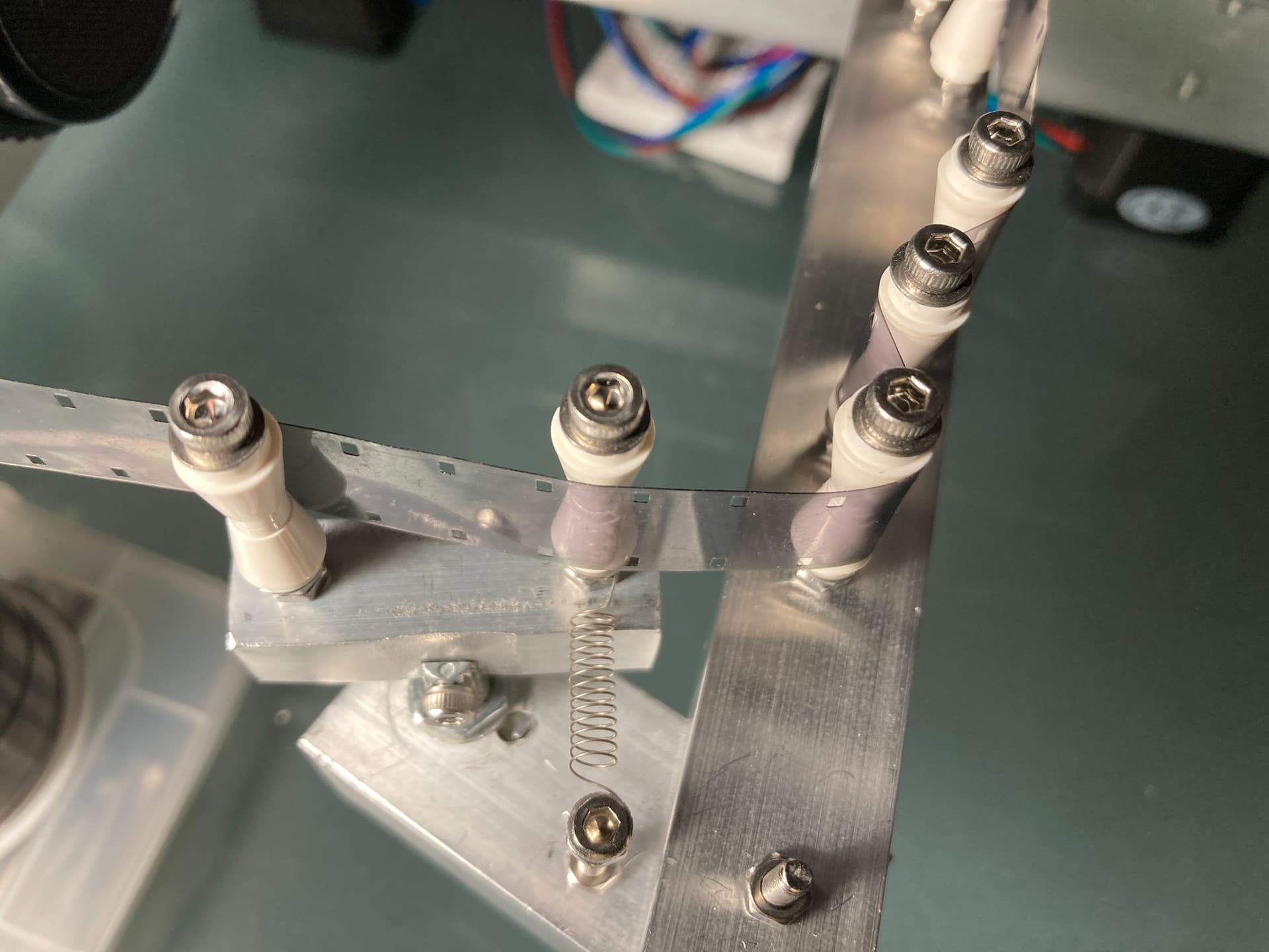
  • Vinyl cutter rollers work well. And with some caveats, so did the Lego cones that are used as posts (check the video). Although the later are a bit tricky to setup.
  • ToF sensors did not yield the results expected when measuring the spool inside the reel, and these were 16mm. For 8mm it would be worst.
  • Learning a lot was the best part. Now switched to FreeCad, Pico, I2C, all of which will be used forward in the project.
  • A scanner found a new purpose. Concurrently with the work in this project, I came across the Develocorder. It was a film based seismology recorder used from the 60s to the 80s and… you guest it, it uses 16mm film to record continuous earthquake data. This 16mm film type in particular has no perforations! so the approach by something like Snailscan would be a great fit for these.

Love to hear any ideas to explore this project forward, feel free to share your successes (and also failures). Of particular interest are sensing tension for stop-motion scanners, and holding tensions for stepper driven scanners.

Thank you

5 Likes

If the goal is to determine the distance the film has traveled, wouldn’t it be easier to put an encoder on one of your rollers and just measure the distance traveled? If you have a capstan, where the film doesn’t slip against the roller, this should be a pretty accurate way to do it.

Thinking some more about it, I wonder if you might also have issues with shrunken film, or loosely wound film, where the apparent distances from the sensor could change quite a bit, giving you bad results?

Thank @friolator, good questions.

That is certainly a way to measure travel distance. I believe it would still be necessary to measure tension in the configuration where both reels are driven by steppers. One can drive pick-up stepper based on the distance travel in the encoder, and supply film to keep tension within a range.

The Gugusse Roller project which uses a form of capstan, and that is certainly an option. In that case, I think it would be necessary to have two mechanism/sensor for tension, again, provided steppers are directly driving the reels.

That’s in addition to the ToF sensor inaccuracies, and yes it adds to the ToF sensor problem.

that seems like a lot of work but should be doable. At minimum you’d need something in the middle to measure the tension and then react accordingly, like a load cell (I think this is what the MWA scanners use).

this is why we’re using the tecknic motors for feed and takeup. they’re designed to do things like hold the film in position, with two motors working against one another. then the third motor (the capstan) handles actually moving the film. In this way, feed and takeup just do one thing. regardless of the amount of film on either side, the motors will hold the film where it is, until the capstan makes it move. If one side detects slack, it automatically takes that slack up. If there’s too much slack (say the film broke, or a reel ended and it’s unthreaded), the motor simple stops. You set the parameters for these actions in their software, it gets uploaded to the motor, and lives in its firmware. Very much set-and-forget.

The low budget way to do the tension sensing would be a dancer arm and a potentiometer. But if you’re looking for something cool, I think you should check out load cells.

1 Like

I know it’s customary to introduce this first and I will, so sorry for the intrusion.

Why not use continuous transport with a pinpoint laser detector?
It is also possible to regulate the speed of advance with a counting of the pulses.
I don’t use a capstan and it works very well,
only two stepper motors, a film guide and a laser detector. All driven by a Teensy board and stepper drivers.

Sounds cool. Will be definitely checking this option.

  • Continuous motion does not work well with rolling shutter sensor. Acknowledge that one could switch to a global shutter, with a significant budget change. The HQ sensor price, for its resolution is a bargain.
  • Develocorder does not have perforations. Nothing for the laser to detect.

Laser detection for perfs, in my opinion, is a bad idea. It doesn’t take into account issues with broken film or missing/damaged perfs, and often has trouble with clear film (vs film that’s dark between perfs).

Still to be worked out, but the basic way we’re going to handle framing with Sasquatch is as follows:

  1. Move motor whatever number of steps is necessary to get the frame into position.
  2. Scan frame
  3. As part of the perf/frame line detection we will determine where the frame lines are relative to the expected location. If they’re off but the whole frame is in the image, we will go with it and adjust positioning on the next move to re-center the image.

I’m also thinking that we may keep a database of the motor positions for each frame scanned, as a metadata sidecar file for the scan. This would allow us to load the same film up, set the zero frame at the beginning, and jump to any frame we want, even if there’s shrinkage that changes the frame size enough that things would be off over some length of film.

Just curious on the Develocorder film - what would your output file be for something like that? one long strip image, or a bunch of separate frames? It seems like a seismograph would need to be a single, long image to be useful. (of course, that could be stitched together from separate frames. But that’s a tough problem with alignment, unless there are some kind of reference marks on the image itself you can use to avoid overlaps or gaps.

1 Like

Detection of perforations by laser works on all films (white, black, transparent, etc.). You must to use a laser that works by reflection.
The problem of damaged perforations does not occur often and on few images. For the laser to lose a performance, the performance really has to be badly damaged.
The simplest is always the best !

It’s not that uncommon actually. We have scanned millions of feet of film on our ScanStation, and see damaged film all the time. Sometimes 6-8 inches of perfs are shredded or almost entirely missing, yet we’ve been able to scan it. The ScanStation doesn’t use a laser perf detector, it uses machine vision to spot the perfs and frame line, and is able to plow right through film that’s really badly damaged.

The combination of knowing where you are (an encoder on the drive motor), a transport that doesn’t allow the film to slip, and some very fast machine vision testing of each frame will allow for scanning of anything, even film without perforations.

There’s another major issue with laser detection, and that’s if your scanner is built to handle more than one film gauge. The laser will need to be moved with each gauge, and it will require recalibrating (most likely) each time you do this. I just don’t see it being a good solution unless you’re working within a controlled set of parameters (one gauge, all good film, etc).

1 Like

Sorry if my words sound arrogant, that’s not my intention and I don’t know enough English to understand all the nuances of the language.

I think we need to differentiate between film scanning and professional restoration of badly damaged film. My reality is that damaged film is rare and I’m not a beginner, although I can’t calculate the number of miles scanned. Honestly, I don’t remember sacrificing a dozen images because of faulty perforations. Here, my reality does not match yours. I’m not saying it’s impossible, just rare for me.
So why for me design a complicated and expensive system to solve a problem that is an exception.

Another argument is that I have not been entrusted with films of great historical value.
I have not had an original version of Abel Gance’s Napoleon, or the Kennedy murder scene in my hands. Of course, all films are important memories that deserve to be treated with the greatest care, but if I had to cut 9 images from Uncle John’s wedding (that is 1/2 second), I think that history would forgive me (and Uncle John too, may he rest in peace).

I will put some pictures of the scanner I built, which allows me to digitize all the formats of the films from 8 to 35mm, to illustrate my remarks.
PS: changing format and repositioning the laser is done on two axes with micrometers, it is fast and does not pose any problem.

Best wishes and congratulations for your work.

1 Like

I have been away for work. Thank you all for your feedback and suggestions, providing some info in the context of the first post.

Great insight. Basically I am trying to achieve moving the film accurately without a capstan. And have not discarded using one as a fall back plan. Keeping the steps required as a side cards is an interesting idea.

The output file requested is a bunch of separate frames with a significant overlap.

My limited understanding is that these have a “time code” but is not an actual timecode in the video sense, more like a control-track in the video sense… a square wave with time clicks.

Having steppers as supply and take up wasn’t bad for this small project, and it is a mechanically simplified approach. But it adds a level of complexity (having accurate size of spools), which I tried solving with the ToF sensor. Thanks for the suggestion of the loadcell, that is a cool alternative.

@Roland thanks for the comments and feedback.

One of the film types that I am hoping to address with this mechanically simple scanner does not have any perforations. For other films with perforations, a laser detector may be an option, but not in this case.

I would agree that simple is better. That’s why I tried a simple mechanical approach, but without perforations, laser is not a feasible option.

I just spent about an hour and a half on a remote tuning session on the ClearPath motors for Sasquatch, with Teknic support. At the end I asked the tech about your scenario. The feed and takeup motors we’re using are MCVC models, which lack positioning capability and are therefore less expensive. We chose these because what we need is for the motors to hold the position, not drive the film. The capstan is an MCPV motor, and does the driving.

When I proposed a setup where you used one MCVC and one MCPV without a capstan, he thought this was an interesting idea, but said it would probably be a bit more complex in terms of the programming. In this setup, you’d have one motor that’s just constantly pulling the film away from the other, to keep the tension. You could use HLFB data from the motor to react when there’s too little or too much tension, and built-in brakes when the film either runs out or snaps at a bad splice or something (this is defined as the motor moving at or past some predefined RPM for a set interval measured in ms). The other motor would have positioning capability, and could be used as the driver. With the MCPV motors, you can do things like speed ramps, position measurements, etc. I think going in reverse in this setup might be kind of tricky, but should be doable when the motors are properly tuned.

His suggestion, however, was to stick with the three motor capstan setup, as it’s conceptually easier, and probably programmatically easier to deal with.

Having their controller, which is only $99, handle this stuff is nice. I believe for a lot of what the controller can do, their Arduino library lets you use the Arduino IDE to write the code, maybe? I’m not exactly sure how that works, because we are using the C++ libraries, which are probably a little more robust, but you can look at all the ClearCore libraries here. and the arduino library is here.

That’s extremely nice to have that kind of support! Does is come free when you’re a ClearPath/Teknic customer or is it paid support?

I assume free. I’ve never paid for support and they’ve always been helpful. It may help that we’re 4 motors, 3 clearcores, two clearcore expansion boards, a power supply and several cables into our purchase with them, but even when we just had the initial two motors they have always been willing to chat or email.

1 Like

Thanks for the information @friolator.
Teknic motors are indeed a great solution, looks like these have excellent capabilities and flexibility.
If I understand correctly VC = Velocity Control and PV = Position/Velocity Control.
I guess the setup of the Snailscan setup -as it stand with two steppers- would be akin to dual MCPV. But for the application, it would be sufficient to have one MCVC and one MCPV as you mentioned.

Probably so. There are added complexities of controlling position on the take up, I think you pointed at some of these above (loose winded spools, etc.) and the bottom line is that the necessary position displacement for one frame will vary with the changing diameter of the take-up spool, as the spool gets bigger. Similar complexity than what I am working with on the two-stepper setup.

The capstan makes the movement of film a bit simpler, since the displacement is not subject to the size of the spool. Once you know the diameter of the capstan roller, the steps per frame will not change.

One of the findings of this trail is that the setup actually works better than expected, and it was not hard to move the film precisely if the spool sizes were well known (measured). The challenge was that the sensors to ultimately calculate the spool diameter accurately did not yield good results.

One test that I still would like to do, is to run the setup on pure math and see how it holds. In other words, knowing the initial diameter of the spools and the film thickness (both measured with a caliper), one should be able to calculates/keep track of the diameter increase as the spool fills. Obviously that is a perfect world -which is not the reality of an old film- but I think is worth checking.

Meanwhile working on a dancing arm with a potentiometer for the next round. If the previous test is somewhat successful, for the develocorder film it should be easy enough to keep track of the position based on a mathematically calculated take-up reel, and control the supply reel to strictly keep a certain tension measured with the arm.

Again, appreciate all the comments and feedback.

So something to keep in mind is that you can only use the motor in one “mode” at a time. They’re listed here: Videos and Articles | Teknic click on ClearPath Operating Modes, and there are videos showing what each one does. switching modes isn’t something that you can do on the fly, so you basically pick one for that motor, set it up and that’s that. Which is why I was thinking one in torque mode (to keep the tension) and one in positioning mode (to move the film, while the other motor constantly pulls on the film).

the capstan definitely makes it easier to calculate position. The other thing to keep in mind with reel diameters is that different films will have different thicknesses. Polyester film, for example (Single 8, many modern film prints, etc) is significantly thinner than acetate film. And film with Magnetic soundtracks could add a bit of thickness to the film as well.

1 Like

Thanks. The above pure math is only for testing, hopefully I will learn something in the process.

Here is the first mechanical take of supply-side dancing arm (potentiometer).

Time do some wiring and coding.

nice. That’s very similar to the tension loss sensor on a Magnatech audio dubber.

The thing circled in red has tape threaded under the narrow roller and over the bigger one. When the narrow one drops (it’s on a spring, trying to pull it down), tension is lost and the machine stops.

The rollers in yellow are spring loaded and handle the tension on the tape, which comes from the right, across the top of the big sprocket wheel, under the top tension roller, over the upper drum, across the three heads, around the bottom of the lower drum, over the lower tension roller and across the bottom of the sprocket wheel, then down to the tension loss arm.

The white plastic bits are used to hold the film against the sprocket wheel and are reversible - one side is used for 16mm and one for 35mm.

1 Like

@friolator thanks for the transport of the Magnatech, interesting design.

Had the opportunity to do an initial testing of the potentiometer dancing arm, it worked well. It is powered with the 3.3V output from the Pico board, and initially the ADC values were jumping around a bit. For minimum conditioning a 1 uF capacitor was placed in parallel to the potentiometer, and also a 100nF capacitor to quiet the middle leg into the ADC, and that basic conditioning was enough to get good stable readings.

The proof-of-concept algorithm advances the corresponding steps for one frame (measuring the radius of the pickup reel manually), the frame is moved in 4 steps, and after each quarter step, the supply returns the tension to a preset range.
The purring sound is the supply-stepper doing short ramps with acceleration/deceleration until the set tension is reached. The tension is maintained well throughout.
Again, this is a proof-of-concept first run, the coding needs lots of improvements.

The missing link to make this work precisely is a good way to measure the size of the pickup reel as the scan progresses.
I think my next step is to implement a pure-math pick-up driver and see how many frames before it needs significant correction. Basically the problem to solve is a work around to the failure shared, the ToF inaccuracies.
Thanks again for the feedback and ideas, all well received.

2 Likes

Providing an update on the progress (or lack of progress).
I implemented a pure-math pick-up driver, and it works fairly well. The caveat is that the dimensions of the pick-up spool and the film thickness are key variables for the equation.

An alternative been considered, to eliminate the measurement requirements, is a capstan driven stop motion transport.

Here is a first draft, which reuses some of the components in the Snailscan first version above.

For simplicity, the capstan will be driven by the same type of geared stepper. Two tension sensors will be used to maintain tension before and after the gate-capstan block.