Yes, it is ![]()
Here is my totally empirical summary, the point of view below is framed by these.
- Angle of bend around a post or roller adds tension to the force needed to move the film. In my case, I had the rubber rollers with bearings (little friction) and the loose-lego-conical-posts without bearings (more friction). In general, the larger the bend, the more friction.
- Old film is less flexible. Larger tension was needed to flatten the film on the air-gate-posts. Less tension would bow the film. Thought this could even be used for narrow focusing. In my case, the space between the gate-posts is larger, because I wish to capture almost 3 frames of 16 mm (one frame with more than two halves), consequentially the play bowing was more noticeable.
- Because of the old film lack of flexibility, and the narrow lego-posts it was necessary to avoid large angles about a post, or risk the film breaking at the perforation (experienced it) when using more tension.
- Eliminating the variability of the increasing/decreasing spool takes away one more uncertainty. The less uncertainties with areas I have the less know-how, the better.
- The transport is intended to be 16 and 8, without any changes other than software. This is an aspiration, but the preliminary results were promising.
With that thinking framework, a few comments.
I was less concerned about the load-cell effect of the supply-reel angle changes, mostly because my lack of know-how on the cell, but you have a point.
I used two kinds of post, the narrow lego (conical only touching edges) and the wider rubber-roller-bearing (flat full contact). With old film, I saw bowing on both. The rubber is probably closer to your design, but on yours, these are only touching the edges, I think the opportunity to bow is there… similar to the lego (only touching the edges also). All speculation, testing is king.
Based on past experience (which may not be relevant to your rollers) I would expect some uneven bowing (very exaggerated in the illustration).
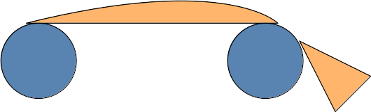
The angle on the left side does not change, the angle on the right side changes, providing an opportunity to bow differently than the left side. This may be so minimal that it may not matter, again, just mentioning it given the attention to detail on your work. Just keep an eye for it, and see if it matters.
Same here, with the added camera sensor and sensor software learning curve.
A big difference in the path is the type of motor used, probably cannot oversimplify/equate film paths of different motor kinds.
I’ll shed some light on my path design, a path for steppers. In very old posts, I started with an inverted V, with 3 rollers on each side of the gate.
Then came the proof of concept for the transport with Tof.
First reference to load cells was at the post of the Tof (square path above) from @friolator, but I did not rethink the initial inverted V path.
The first path, inverted V, is nice and symmetrical, and the 3 rollers take away any variations of the spool-size-changes, and two load-cells in the second roller of each side would give perfect feedback to control the steppers. For precision, one of the gate-edge-rollers can be numerically encoded. As I write, I think this is a neat transport alternative, and one that I may revisit down the road.
The one turn-off was that it was large, in order to make space for the large sphere, plus two large reels virtually in line. That’s when I started playing with ideas of a wrap-around path, to keep the project at a reasonable size for storage.
Then came the ToF path, which is virtually a square, and provided experience on turning old film.
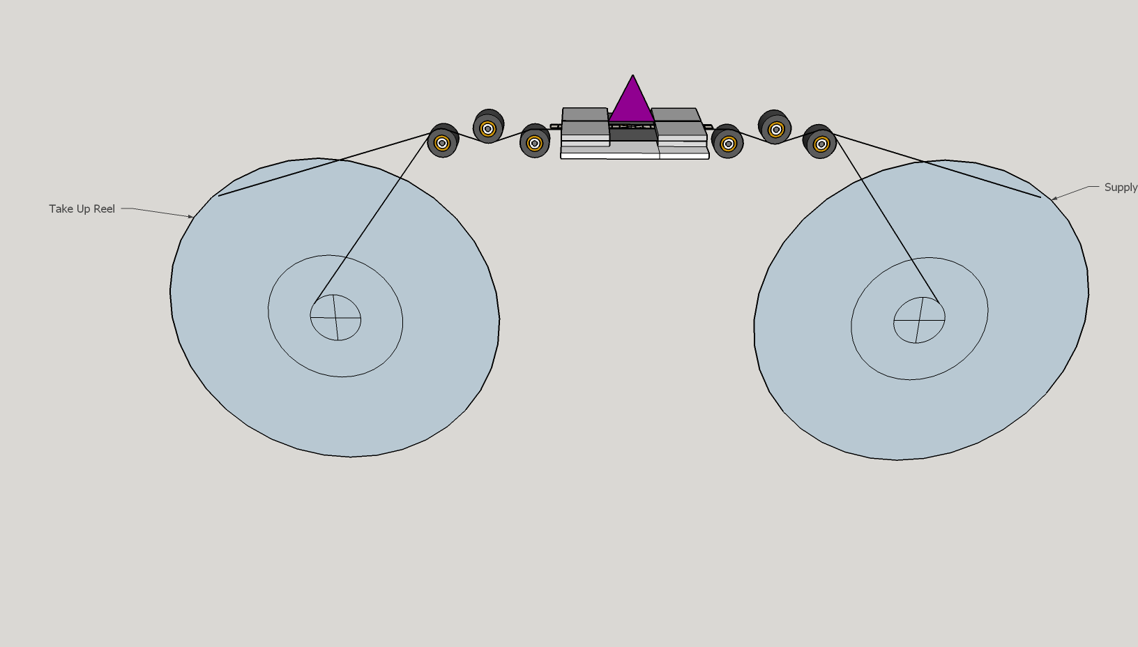
The new path is based on an octagon, and it is virtually symmetrical between the supply-side and pick-up side. The pickup side has the capstan, and supply side has a roller where the capstan would be, which is the only difference (the middle roller in the 3 at the bottom.
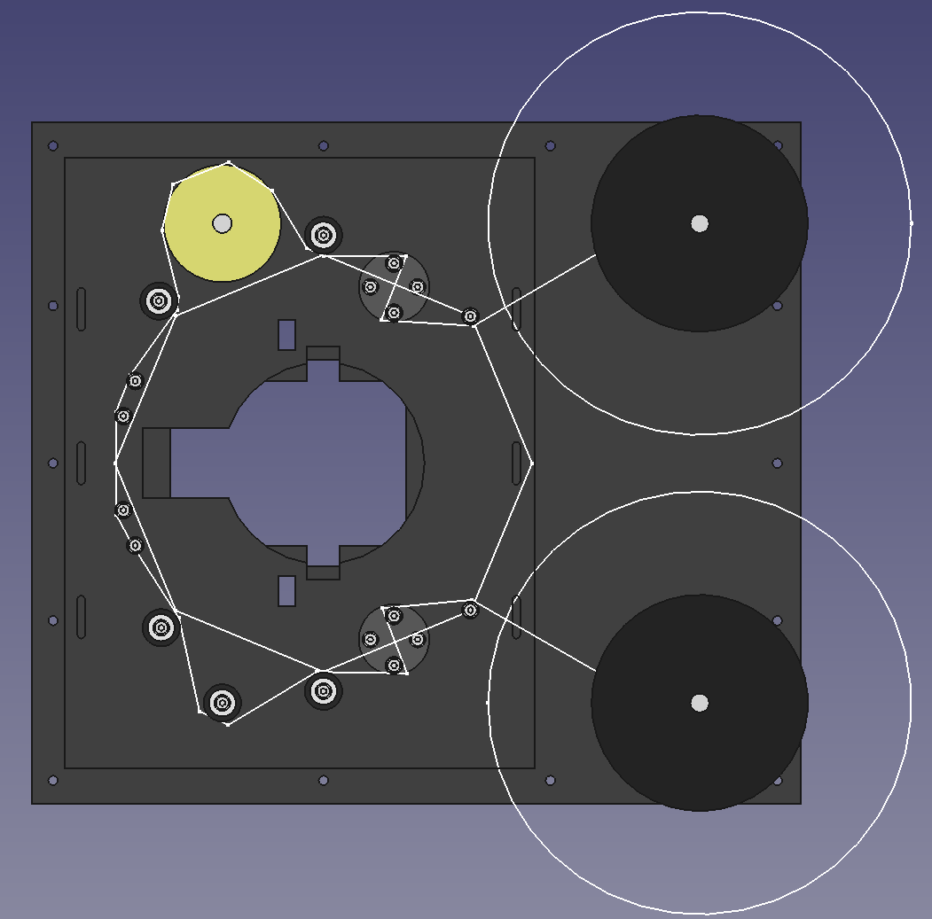
Tried to eliminate variations induced by spool-size, both sides start with an entry post (right side of the octagon). Both sides have identical dancing-potentiometer, the entry-exit angle of the potentiometer is fixed by the entry-post and the first roller (from right to left). The next side of the octagon is the capstan (on the top) and the dummy-mirror-capstan, the three rollers at the bottom. The two left sides of the octagon are the gate.
The large sphere needed for 16 mm target (more than one frame) takes a lot of space. When working on the failed prototype, one of the takeaways of the experience was the fragility and rigidity of old film (have a couple of the 16mm close to 70 years old). So was looking for a compact arrangement with a path minimizing sharp bends. The entry post, with large spools are the only ones would be over 90 degrees (the old 16 mm film is in smaller spools, and the angle would be far less than 90).
So in short, all those rollers help make the transport plate a bit smaller, and lesser the film bending.
Please, don’t follow me, I’m a bit lost… but making good progress (paraphrasing Yogi Berra).
I suggest you change nothing until you test it, and use the information provided as things-to-keep-an-eye-for. Perfection is enemy of the good.