The ReelSlow8 Film Scanner

Hmm, the settings aren’t anything out of the ordinary. I think it’s all default except the 5 frames before/after thing.

The first step is always getting a nice noise profile from some neutral part of the image:

I don’t know much about the app, but I’m guessing that “Quality: 93%” is a good thing. I’ve seen it give worse results when that quality metric was lower.

Then, on the next tab, I have everything set to the defaults. If I go out of my way and turn spatial denoising off, the blue speckles show up a little more:

That’s temporal-only. Enabling spatial makes the last vestiges of blue dots go away (as seen before).

In the comparison in my previous post I may have had a mild Unsharp Mask applied to the final result (I made those side-by-sides a couple weeks ago to show my uncles and have since forgotten), but otherwise it’s almost completely NeatVideo’s temporal stuff doing the heavy lifting here.

2 Likes

Nice, thank you for the quick reply!

I think what this really shows is how important a good noise profile is in Neat Video. I’ve been copying the Neat Video filter from one clip to the next without really paying too much attention to the noise profile, assuming it will be roughly similar from one roll of Kodachrome to the next. Presumably, that’s why my results are not as good. (To be fair, the instructions for Neat Video do repeatedly point out the importance of a good noise profile :upside_down_face:).

1 Like

October: Lots of Software Work

I attempted a full 3" reel of Super8. It took 7 hours. There was a lot of babysitting. The last 10% of the reel in particular seemed to fight against my software and took probably half of the total time. Even when things were going smoothly, I felt like I had to sit perfectly still to avoid shaking the desk. I’ve got all 44GB of the resulting 3,609 frames, but there is some work before it’ll be ready to do the other 39 reels in my collection.

So I did some of that work in October.

I started with code that expected everything to work smoothly, failing poorly whenever it didn’t. The real trick will be to transition right past just detecting when things don’t go as expected and instead teach the software how to correct for common problems.

Partially out-of-viewport sprocket holes

The sprocket hole detection (that we were talking about in the SnailScanToo thread) was the first part of that work. I ended up dialing some of that complexity back. Now that I’ve got nice control over the vertical alignment, the problem became a little easier. I still calculate the center-of-mass of the over-exposed pixels. But that falls apart for sprocket holes that are half off the top or bottom of the viewport.

Here is a super simple scheme to make it work, even at the viewport edges:

  1. Once at the start of a reel, find a nice, clean, normal sprocket hole and measure its height.

“Height” here is as simple as finding the first and last (contiguous) image rows that contain over-exposed pixels. When the alignment is very close to vertical, this is fine. I actually measure two or three “nice” holes and have the software use the average height.

  1. With a known-good “prototype” sprocket hole height, we can use sprocket position estimates from several sources and average them all together. Each estimate gets a certain number of votes for where it thinks the y-coordinate of the hole is and at the end the votes are averaged together.

    • The center-of-mass estimate gets 2 votes.
    • The first over-exposed row + height/2 gets 1 vote.
    • The last over-exposed row - height/2 gets 1 vote.

Then, you just use these simple exceptions:

  • If the hole is falling off the top or bottom of the viewport, throw away the center-of-mass votes.
  • Hole touching the top of the viewport? Throw away the first-row vote.
  • Hole touching the bottom of the viewport? Throw away the last-row vote.

It’s very straightforward to implement. And for normal sprocket holes, all the votes basically land on the same Y value and it’s incredibly consistent. Even the dirty or lightly torn holes I’ve seen so far end up close to their center. And it continues to work (just not quite as robustly) without modification, as holes scroll into/out of the viewport.

Frame height

Part of speeding things up will be advancing an entire frame at a time (instead of in three smaller moves). To do that, I need an estimate of each frame’s height. That should be as easy as measuring the distance between the center of two sprocket holes, but until now (because of the zoom and framing), I’ve never had two full Super8 sprocket holes in the viewport at the same time.

With the new out-of-viewport sprocket detection, I don’t need to have them completely on-screen anymore! Now, while I’m grabbing the initial known-good sprocket heights at the beginning of a new reel, I can advance by half a frame and grab the sprocket hole separation (again, averaging two or three of them together to get some of the noise out).

So now I’ve got all the quantities I need for a much faster film transport.

Next I’m adding the notion of a frame ID to the app, which increments each time a sprocket hole goes by. Until now, there has been a rigid sequence of “advance by X to measure tension, advance the hole off the top of the screen, advance as much as you guess it’ll take to center the next sprocket hole, take an exposure”.

Now the plan will be something closer to “here is the list of frames we don’t have images of yet; you know which frame you’re currently looking at; plan moves that will center the frames we don’t have yet, then capture them.” Built into that is the idea of smaller correctional moves if any of our guesses/estimates were wrong (say, if the film wasn’t wound tightly and it slips, etc.) Ideally most moves will be correct on the first try, but having it able to take care of itself without being babysat the entire time is the goal!

Film Tension/Focus/Bow

I had a few minutes one day where I was curious about @PM490’s warning of film bow. I thought I had designed a test to check for it. Now that I’ve seen the results, I’m not so sure it tested what I thought it was going to. :sweat_smile:

Still, the results were interesting, so I thought I’d share. Here’s the set up:

  1. Tension the film to some level, T.
  2. Adjust the camera to be in the best possible focus (using the image’s pixel value standard deviation as a proxy for focus).
  3. Do a sweep across many tension values, measuring the focus at each point (keeping the camera position constant).

Repeat that for several values of T, getting a new curve on this plot each time. Finally, it works best when the curves are all normalized to their individual peaks.

The sanity check here is that the peak of each line falls at the tension it was focused on. That’s a good start. (The purple 180g line is arguable. I think there might have been some PETG creep by the time I got all my ducks in a row for that data series.)

Beyond that, reducing or increasing the tension (away from the value used for calibrating the focus) always impacts the focus negatively. That also makes intuitive sense to me.

My hypothesis for the mostly-linear decline as you increase tension (to the right of each peak) is from the physical deformation of the 3D printed spindle holder. The tension is presumably tilting the bolts closer toward the camera.

The most interesting part is the width of each peak. You can summarize it like “the higher the tension you start with, the more tolerant the focus is to variations in tension”. I don’t know whether that finding directly supports the existence of film bow (like I was hoping the experiment might), but it definitely seems related. At lower tension levels, film bow would play a larger factor. And it’s at the lowest tension levels that we see the focus falling off quickest. At higher tension, you’ve basically stretched all of the bow out of the film path, so there is less difference in that tension neighborhood.

I don’t know that there is much to learn here besides doing the tightrope walk between targeting the highest tension you can without also posing a danger to the film. For my part, I think I’m going to target something around 170g.

What’s Next

Hopefully I’ll have something really cool next time. I just spent the last two weeks designing a circuit for a new peripheral for this machine. I finished the PCB layout and placed the DigiKey+JLCPCB orders last night.

If it ends up working, I would be excited if it eventually saw wider use by the community (at least for stop-motion machine designs). It seems like it has a lot of potential to be helpful. And I kept Raspberry Pi signal voltage compatibility in mind while I designed it. This would be a completely open-source release once I’ve got any bugs worked out.

Still, until I can see it working with my own eyes, I’ll keep it a surprise for now. :smiley:

3 Likes

Nice work, and thanks for sharing @npiegdon. Would like to understand a bit better if you can elaborate…

Not sure I follow how you go from standard deviation to focus.

If I follow, all the curves are normalized to their peak (on the sharpness axis)… and the peak of the curve is the tension at focus. Since the x axis is tension the curves are shifting to their focus-tension point. Wonder how these would look if the x axis instead is Tension - Focus Tension + 180g, making the x position of all the curves centered at their focus.

Bowing?

Also, the higher the tension, the flatter the film.

One important factor that is not mentioned is what was the lens aperture. While the smallest depth of field would be at the lowest f, it is also typically not the sharpest f.

You can use the standard deviation of all the pixel values as a measure of the (relative) focus itself, assuming you’re taking a picture of the same thing each time.

For something to be sharp, it means the difference between the adjacent pixels (or “deviation” :smiley: ) is higher. It’s easier to think about in the other direction: as you go further out of focus, all of the pixels begin to blur together, which naturally brings their values closer to one another. In that case, their cumulative differences from the average must be smaller: so the lower the std dev. the worse the focus.

Again, this only works as a relative measurement if you’re comparing apples to apples. If you’re changing the image (or even the framing by a little), all bets are off. But if you’re holding very steady and only changing one small thing at a time, it’s almost the simplest possible measurement (being a one-liner in OpenCV and a reasonably fast computation).

I usually only calculate it on the center 70% or so of the frame where I know there shouldn’t be any over-exposed parts (sprocket holes, frame edges, etc.). Those extreme values can throw the std dev off faster.

Did you mean like this?

That makes it even clearer that I held the 180g tension longer before I started recording data points (but after I set the initial focus) and the plastic had a chance to deform.

I never change the lens from f/4.7. Coinimaging’s review (choose the Componon-S 50mm and go to page 3) seemed pretty definitive and a couple cursory checks of my own, back when I first got the lens, seemed to confirm those results. So, I just leave it there 100% of the time.

That said, you’re right that narrowing the aperture would have made those graphs spikier. :slight_smile:

Thank you, yes.

One observation from the new chart is that focus changes differently with higher/lower tension. The drop is steeper with less tension… that would be consistent with film warping/bowing.

Indeed.

Hi. I’ve been following this build, and now when my version 1 of my scanner hit a brick wall, I’m biting the bullet and building the scanner from scratch. One thing that I am curious about is what type of stepper motors you are using for the transport. Is it the same as the motor that does the auto focus?

The transport motors are a little smaller. They’re a pair of plain 1.8-degree NEMA 17 steppers (instead of the fancier 0.9-degree NEMA 23 on the Z-axis).

I think I happened to get the 17’s from Pololu (item #1200), but any should do just fine.

For 8mm work–and especially smaller reel sizes–these are probably overkill. I usually run them at around 40% of max current (of the little controller board, also from Pololu) to keep them cool and I still get the impression that they could rip the film apart if I didn’t have the tension sensor cutting the power anytime I write bad code. :sweat_smile: (Albeit, this is at 42V.)

And, again, with small’ish reels, the 1.8-degree per step is plenty of resolution from about 1/32nd or 1/64th microstepping. Once things are under tension, there isn’t any backlash and you get lots of control with very small movements possible.

I’ve come far enough so everything is hooked up and I can start writing som code. However, how did you get such clean and responsive signal from the load cell? Running it in 80 Hz gives way to unstable readings. 10 Hz gives a bit to slow response but still drifts quite a bit.

Drifting/floating around a few grams-worth of tension readings is normal. It looks scary because lots of digits are changing in the raw data readings (like, the lower 12-bits practically seem random), but the upper bits–at least with the load cell I have–are quite stable.

One key here was that I didn’t use the little HX711 board that came with my cheap Amazon load cell. I swapped it out and used SparkFun’s HX711 board which seems to be known on forums as having better noise characteristics. (If you compare the two, you’ll see more and larger capacitors on the SparkFun board vs. the generic pack-in boards.)

The code isn’t in quite as shareable/public a state as I’d like, but here is what I’m using. Eventually this will be on GitHub and more complete.

For all of these snippets, assume these are defined someplace. (I prefer reading the shorter names.)

using s8 = int8_t;
using u8 = uint8_t;
using s32 = int32_t;
using u32 = uint32_t;
// etc.

Arduino code for reading it fast (minus the part that resets the other controller if it hits an extreme limit).

I took basically ALL processing and extra serial data out of this part to keep the reading-rate as high as possible. I don’t believe it starts the next measurement until you’ve read the previous, so the faster you can shift the data out of the HX711, the sooner the next reading will begin. I routinely see 92Hz readings using this despite their claim that it maxes out at 80Hz:

constexpr int DataPin = 3;
constexpr int ClockPin = 2;

void setup()
{
  Serial.begin(57600);
  pinMode(ClockPin, OUTPUT);
  pinMode(DataPin, INPUT_PULLUP);
}

void loop()
{
  // Wait until the HX711 tells us it has finished a reading
  while (digitalRead(DataPin) == HIGH) { }

  noInterrupts();

  static u8 reading[3];
  for (u8 &r : reading) r = shiftIn(DataPin, ClockPin, MSBFIRST);

  // Selecting Ch.A with 128 gain just requires a single clock pulse
  digitalWrite(ClockPin, HIGH);
  digitalWrite(ClockPin, LOW);

  interrupts();

  // Write an arbitrary delimiter and our raw reading
  Serial.write(0b10101010);
  for (u8 r : reading) Serial.write(r);
}

So, there’s zero processing going on there. Just handing off the raw data directly through the serial port as fast as the HX711 can generate it (plus a delimiter byte so we can tell where each reading starts/stops).

Then, on the PC side:

Interpreting the signed 24-bit response as signed 32-bit. (This is a little more pseudocode’y because I had to pull it out of a larger response-parsing framework):

    while (we read any byte that isn't 0b10101010) keep reading bytes until we do...

    u32 sensor = 0;
    for (size_t i = 0; i < 3; ++i)
    {
        u8 byte = readAByteFromTheArduinoSerialConnection();
        sensor = (sensor << 8) | byte;
    }

    // Pad out the negative sign through the 32nd bit
    if (sensor & 0x800000) sensor |= 0xFF000000;

    return std::bit_cast<s32>(sensor);

That’s still a pretty straightforward, direct conversion that hasn’t massaged the data in any meaningful way.

Now we’re on a fast PC with a plain int value that we can work with. Before we can convert it to a tension reading, you need two experimentally-determined values:

The zero point (“tare”) seems relatively stable at a given temperature. I used to measure it each time I started my scanner software but I’ve noticed that it’s usually around the same value. To get this you just take a few thousand measurements (as above), average them together (in a double), and call it your zeroOffset.

The load cell’s slope was determined using the little classroom scale I showed in an earlier video. It’s presumably different for each load cell. Here is my lab notebook entry from that day that shows how I determined the value for my load cell:

Same situation here. Put the load cell under some fixed, known tension, wait a couple minutes, then average a few thousand readings to get each data point. Mine (using the data above) happened to come out as -929.86, where the negative sign means I probably have it mounted “backwards”, but that doesn’t matter so long as this value has the correct sign.

Once you’ve got those two per-load-cell values in hand, turning the raw sensor reading into a tension value (in whichever units your known values were in) is just:

double tension = (reading - zeroOffset) / LoadCellSlope;

And from there you can do whatever you like with it. In my own software I display that value directly in the UI (rounded to the nearest 2g), but in some of the other processing steps I keep a running average of the last three data points I’ve seen. So it’s still coming in at around 90Hz, but it’s got a little bit of smoothing (sort of like reading at 30Hz) so it’s not as jittery.

Almost all of the noise is down below the decimal point and fractional grams don’t really matter for our purposes. The smallest tension window we might need to consistently hit is on the order of 10g or so.

Now, all of that said, this has been my experience with the single load cell I have sitting next to me. I don’t know anything about the variability you might see across a whole population of the things. Hopefully your sensor will be able to give you useful data, too!

3 Likes

Very grateful for the detailed write up! My drifting was a bit more than a few grams and I had a hard time keeping tension because the values fluctuated that much. I have ordered the Sparkfun amplifier and hope that it will solve the problems I was having.

November: Vibration sensor

It’s useful for more than this machine, so I posted about ShakeFinder separately. It turned out really cool. This was the missing piece for fully automating the capture process at a fire-and-forget level where I could just sit next to it while doing something else.

December-April: Vibration sensor video :sweat_smile:

That took forever! To be fair, there was a lot of real-life getting in the way, too, but polishing something up for public release takes so much longer than just making it for yourself.

One of my other hobbies is making explainer-type videos about little projects I’ve worked on (once every year or two) and this seemed like a nice opportunity to make a fun video about a simple circuit. In hindsight, had I known it was going to take this long, I might have reconsidered. Still, I’m happy with how it turned out.

What’s Next

I’ve already added the “did you detect shaking since the last time I asked” and “wait until there hasn’t been any shaking for X ms” primitives to my Arduino code, but the desktop app doesn’t use either of them yet. It won’t be hard to get that integrated with the capture code though.

Beyond that I need to, like, remember what I was doing last year before all of this. :grimacing:

While I haven’t hit all of my research goals (I still want to revisit Köhler lighting and do some side-by-side comparisons vs. the integrating sphere now that I’ve got everything else up and running), I’m afraid this early prototyping phase has lasted longer than the year I set out for it.

That said, the results I’m already seeing are better than I expected. So I think I’m going to try to beeline for getting the software in shape enough to do a first round of captures on these 39 family reels. I’ve been promising these transfers to some of my family members for a while and I’d like to fulfill them in at least a semi-timely fashion.

2 Likes

I love this. The video is great - please make more of them! While the vibration sensor isn’t something I’d incorporate into our scanner, the video is really well done and I love that you document the whole process in stages. Very clear and easy to follow. And yeah, making those graphics is really a pain, but it’s worth it because it helps reinforce what’s happening.

Regarding the vibration - how do you use this in your scanner? Is it just to detect when it’s safe to take an image because there’s no vibration?

I’m curious because it looks like the issue you’re seeing in the video is movement of the entire frame. It seems like that could be corrected for in software using OpenCV or similar machine vision tools to identify the perf and film edges and align them to some fixed location, no? Basically the same idea as frame registration.

2 Likes

Thanks!

The little animation right at the 1:00 mark in the video was trying to answer this. Because the shake signal arrives in the microcontroller as the simplest kind of interrupt/flag, the main app can just clear the “shake” flag before capturing a frame and then check it again after all the color channels arrive. If the shake flag is set, the main app just throws that data away and tries again.

I do have another op built into the microcontroller where it can wait for some amount of time since the last time it saw shaking. So you could insert one of those at the end of that loop: “we shook: throw that data away and wait until everything is still for at least 100ms” before going back to do the retry. Given that my frame captures (averaging several exposures x 3 channels) take ~400ms, in theory, you could save a little extra time over brute-force retries.

But it’s mainly the clear-the-flag and then check-the-flag pattern that guarantees nice, blur-free frames.

2 Likes

May: Sinusoidal Acceleration, APO Lens, Better Movement

It’s nice to be back in the swing of things! I had built up a list of small things I wanted to try and was able to knock out quite a few of them this month.

Acceleration

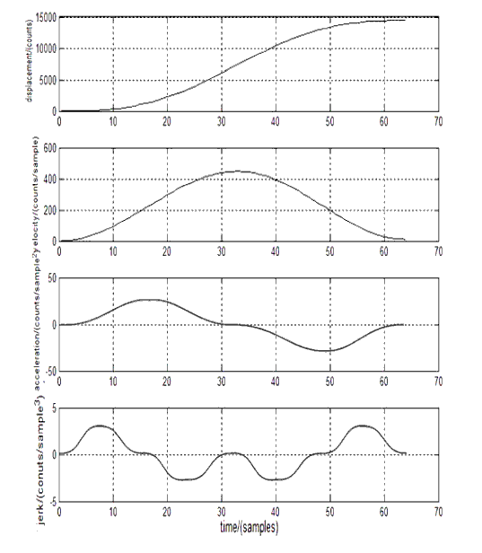
I was inspired by @PM490’s post demonstrating his new acceleration control. For unrelated reasons, I’d recently learned about the classes of curvature (C0, C1, C2, etc. and G1, G2, etc.) so I was on a smoothness kick. I found a paper that described an acceleration curve that enforced G3 curvature (continuous “jerk”) by using sine curves everywhere.

Here’s the relevant diagram from the paper showing each derivative:

I only needed to use 2 of the 28(!) formulas given in the paper to build a little lookup table and now my film transport moves are smooth as butter. :smiley:

Vibration sensor integration

It took as little work as I’d expected to get the “clear the vibration flag, capture an image, check the vibration flag” behavior I described before, retrying as needed. It works amazingly well and I can’t seem to take a blurry picture anymore.

850nm IR

Something I’ve been dragging my feet on has been capturing each channel in its best focus by moving the camera along ReelSlow8’s ball-screw Z-axis. There were still lots of challenges: making sure the repeated movement was consistent (not losing steps) and the image registration to correct any slight transform between channels. I had observed all three: rotation, translation, and scale for just a couple hundred microns of Z-axis movement.

The R, G, and B channels haven’t been much worse off by the camera sitting still. But, without moving the camera, the longitudinal chromatic aberration defocuses the IR channel into uselessness. I didn’t want to start the bulk of my data capture without that 4th channel, but now that I’m more or less sprinting for the finish line, I decided to rethink my approach a little.

The graph at the bottom of Wikipedia’s Superachromat page describes mythical lenses with 3rd-order correction that even bring the IR light range into sharp focus. Those lenses are (tens of?) thousands of dollars though and not made for our type of enlargement.

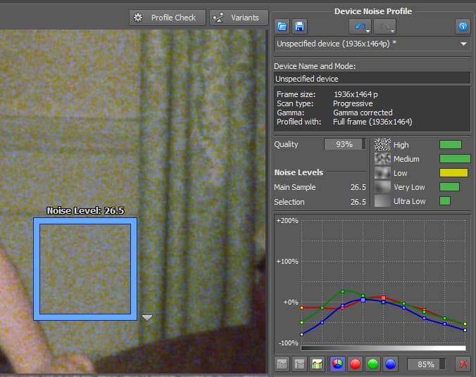
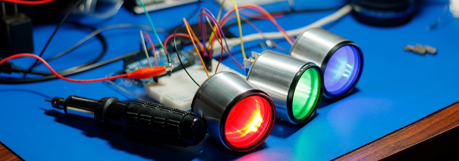
But the orange, “3. Apochromat” line there made it look like some of the lower, near-IR range might not be so far off. My first experiment was “Does 850nm IR work for the purposes of IR cleaning?” I temporarily installed an 850nm through-hole LED in my integration sphere to perform a quick test:

The answer: No, no it doesn’t. :rofl: Compared to the ~920’ish nm LED I’ve been using, the dyes on the film are apparently quite sensitive to 850nm light and the results almost look like one of my red channels.

Changing the light so it’s closer to the other channels isn’t going to work.

APO Lens

Maybe a different lens then? If there isn’t a suitable (or reasonably priced) superachromat lens, lets look at the lists of enlarging lenses that were advertised as having at least 2nd-order apochromatic correction. Maybe that would be close enough?

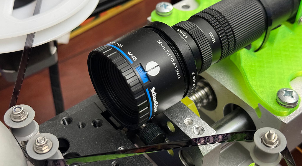
I was surprised to see an almost identically spec’d Schneider lens pop up: the Schneider APO-Componon HM 45mm f/4.

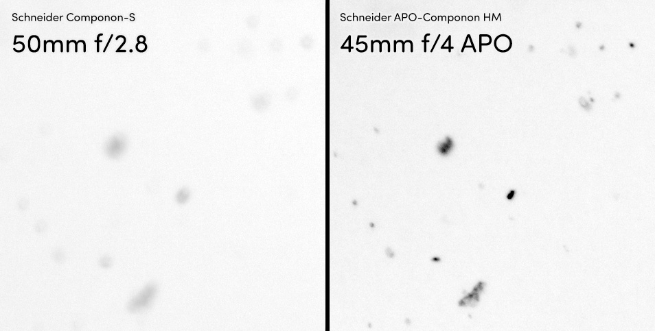
You can pit them side-by-side using coinimaging’s comparison tool. The short answer is that they are virtually identical with the slightest resolution win going to the APO lens and the corner sharpness going to the usual 50mm f/2.8.

Really though, it looks like they’re based on the exact same design but with the second corrective optic changing the focal length a little on the 45mm. The best aperture on both is f/4.7 (which I use exclusively during all testing) and their physical dimensions are the same.

I decided to try my luck and order one. This would essentially be trading my software development time/effort for money by using an off-the-shelf solution that didn’t require any Z-axis movement. My 50mm was $50. After the shipping from Spain, this 45mm APO was $350. :grimacing:

If you’re used to seeing the 50mm lens, this one is blue instead of green.

The 45mm focal length means you’ve got a little shorter working distance. (I should have reverse mounted it but that would require a 3D part redesign that I haven’t gotten to yet.)

To begin testing it, I moved to the best focus position for white light as my baseline for both lenses. Then, I measured how much Z-axis movement was required to bring each color light to its sharpest focus. So the 3rd and 4th columns here are “deviation from best white focus in mm”:

Color λ (nm) 50mm f/2.8 45mm f/4 APO
IR 915.3 -0.862 -0.299
Red 659.5 -0.120 -0.048
Green 528.2 0.108 0.072
Blue 452.4 -0.084 0.024

The focal planes for the APO lens are all much closer to center. All but the green channel require less than half the movement to make them sharpest. The others are all around 1/3 to 1/4 the focal error, which was better than I was hoping for.

(I haven’t observed any of the corner sharpness decrease mentioned at coinimaging. Granted, it was supposedly something like 0.13% difference between them.)

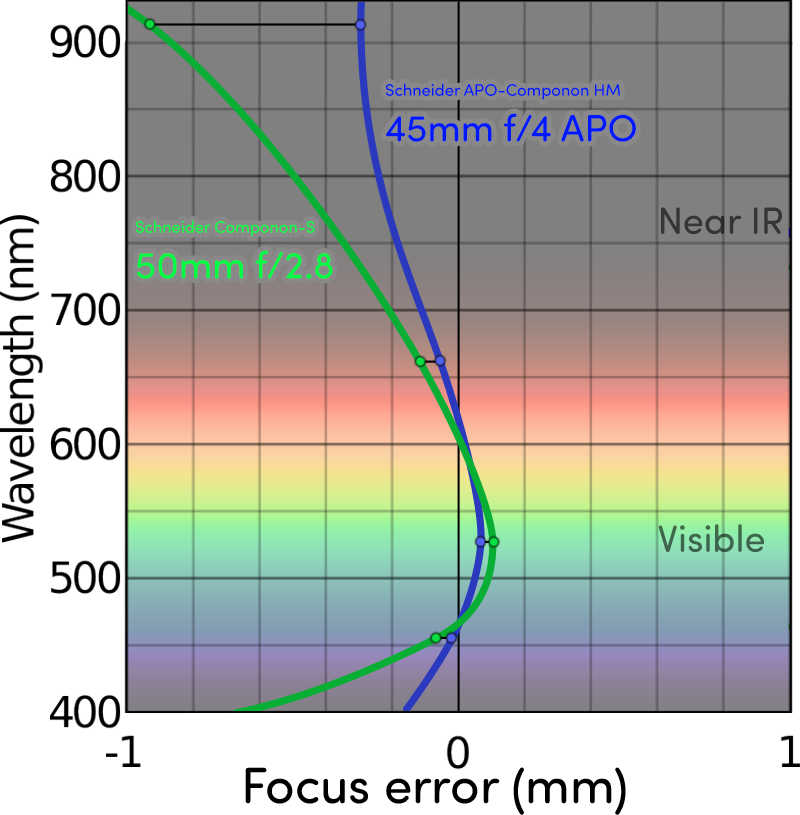
I really only have those four data points, so there is some hand-waving in this graph between them, but this gives a better impression of how much closer to the “white light” center line things are:

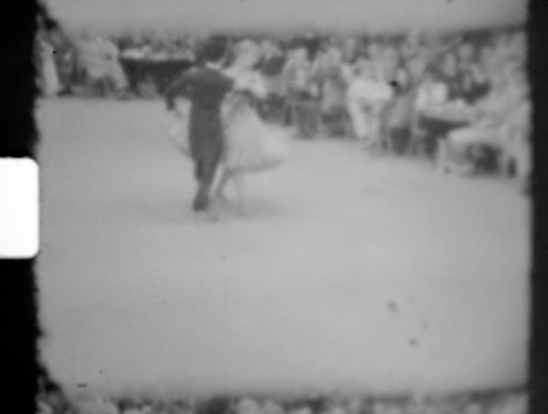
Look at how much closer 915nm is! It’s not completely in focus (because this isn’t a Superachromat lens) but it is now totally workable. Here is some dirt on a Super8 frame:

There is a bit of blur on the right (while white/blue are in focus), but that is almost the amount of blur you’d add before thresholding it to use as an inpainting mask.

This made me very happy and made the extra cost of the lens completely worth it. Besides initial focusing, the ReelSlow8’s Z-axis is now more-or-less vestigial and could be replaced by something simpler/cheaper (a hand-operated micrometer stage?) in the next iteration, dropping a stepper motor and stepper controller board in the process.

Software understanding of continuous film position

To enable the next thing I had to add the notion of “sprocket permanence” to my software. Before, the way I was keeping track of things was quite brittle and could only measure distances based on sprocket holes that remained in the frame before and after. If one scrolled out of the viewport, the app wouldn’t have any idea what happened.

By teaching the software that sprocket holes are spaced more or less uniformly from one another, it can handle things scrolling off without losing its place. Now it keeps track of frame IDs as they scroll by, incrementing each time a new sprocket hole appears (and decrementing correctly when moving in reverse). That opened the door for…

Simultaneous position and tension

Almost a year ago I showed the math I was using to maintain tension while moving. Equation (1) there showed a relation between the number of steps taken by the supply & take-up motors and how that would change the tension.

It worked great for holding tension constant but my simplistic “we seem to be moving X pixels for each supply motor step” didn’t always land where it was supposed to. That is because the motion doesn’t only depend on the supply motor but also the take-up motor. If the tension algorithm was making up for some slight tension deviation, the amount of movement would be different.

I’ve been curious whether the steps of both motors could be related to the film motion in the same way I’m handling tension. After some testing to see how much things moved at various tensions and for various step counts, I was pleasantly surprised to find things behaving quite linearly. Maybe it was worth a shot. So–introducing new constants, c and d with units of pixels/step–we can say something about how the number of steps (S for supply motor steps; T for take-up motor steps) affect the movement of the film (in pixels, Δp) in the viewport:

eq6

If you combine equation (1) from a year ago and (6), you can do a bunch of substitution and get direct answers for S and T that will maintain tension over an exact-length move:

The dimensional analysis works out nicely: the units all agree.

Now the general scheme is to update our constants a, b, c, and d after each move (where we provided S and T and can read the resulting Δτ and Δp from our sensors) by doing least-squares/RANSAC/etc. across two separate linear equations (see (2) from a year ago).

With the updated constants in hand and a desired Δτ and Δp for the next move, we can use (7) and (8) directly to get the number of steps for each motor to simultaneously achieve our desired position and tension in a single move.

This replaces the “make a guess at S and then solve for T using (4)” in a neat way that has been working even better in practice. With very little training it can move entire frames (now accelerated smoothly :smiley: ) and land within a couple grams and a couple pixels of the target, every time.

I was on frame 37 and told it to navigate back to frame 33 and in less than a second it landed so closely that the “sprocket center” and “target” lines in my UI overlapped, all while the tension was held fixed.

It can still suffer from the same degenerate/singular matrix problem I described before: once you’re making the exact same move every time (because it’s so precise), the solutions to the equations collapse in dimension. But I’ve got some ideas for circumventing that including “maybe don’t update our constants if the move was within some threshold of being perfect”.

What’s Next

Things are very close now. I want to do a little cropping to the frame bounds before writing images to disk. This is to both limit the amount of drive space required for a reel but also to maybe help out the image stabilization algorithms with a bit of pre-stabilizing.

I also haven’t done a good tilt/yaw stage calibration since I finalized the film path to make sure everything falls inside the imaging plane and one side of the frame isn’t in better focus than the other.

It’d also be nice to generate a sidecar metadata log with the steps taken, film tension, frame positions, crop boundaries, etc. just in case something goes wrong. I learned a lot the last time I tried to scan an entire reel. I suspect I’m going to learn just as much this next time.

4 Likes

Have you considered that the typical bayer filter array has twice the number of green pixels as red or blue pixels? I believe this would be visible in the image sharpness for each of the three colors.

You are going pretty deep into the issue of chromatic aberration (this is not meant as a criticism). Would it not be worth replacing the color sensor with a BFA , with a monochrome sensor and either use R-G-B led lighting, or white lighting with color filters.

The incredible astrophotographs that amateurs are creating now are typically done with monochrome cameras and color filters. This works because the stars don’t move during the multiple long exposures, and the registration between frames is easy with all those pinpoint light sources.

Three different exposures may not be ideal in production, but it might help characterizing the phenomena.

I am using a monochrome sensor. See the 2nd bullet point in the top post. (Or were you replying specifically to @cpixip?)

Instead of just capturing separate R, G, and B exposures, I also grab IR for a dust channel. It’s been working great. :smiley: Most of my work since my last post here has been on the software side. I have a lot of cool post-processing things to share soon.

My silly profile picture was from an old (circa 2018) experiment where I was trying to somehow make use of color filters. I actually machined threads on these aluminum tubes that would fit the Wratten color filter threads and then made some PCBs to fit on the opposite side. As it turns out, having each color light come from the same angle is important and these things were giant and unwieldy. (I really didn’t know what I was doing at the time!) :sweat_smile:

I eventually settled on LEDs instead.

For now I haven’t been able to beat an integrating sphere setup for the lights in terms of convenience, but I am still interested in the increased contrast that might be available from a Köhler setup (and wet gate to hide all the imperfections).

1 Like

I apologize for not catching that (the mono sensor). Have you done any characterization of the LED’s spectral distribution as compared to either the sensor’s sensitivity and also the film emulsion. You have probably thought pretty deeply about this, given that some LED’s have a pretty sharp wavelength distribution, does that impact the transmitted intensity of each color? I looked at some datasheets and CREE makes some RGB LEDs with individually addressable R-G-B channels with a pretty even distribution, with overlap of each color, some have sharper cutoffs than others. Or, are you correcting in software after exposure?

There are very affordable LED drivers that output a constant current, which allows you to string multiple LED’s in series without the need for current limiting resistors. Easy peasy, so to speak. You could string dozens in fact, as long as you had a high enough voltage to cover the drop across each LED. Then, to control exposure, instead of PWM, you could just use exposure time, though I don’t know how this would work with the sensor, though, with a global shutter, it might be straight forward.

Can you share some specific part number? In general, I would discourage using anything that has a PWM driver, even when the plan is leaving it on at 100%. But the specific part you have in mind may be an exception.

2 Likes