The ReelSlow8 Film Scanner

So, two example devices. If you look at the datasheets you can see example circuits. At the ost basic level, these can be used as two terminal devices in series with the LEDs you are trying to control. The most important thing is to match the current output of these devices to the current requirements of the LEDs. If you have a white LED that needs 30 mA, you use a driver that puts out 30 mA. Secondly, if you know the voltage drop across the LED, you can determine how many LEDs you can string in series, given the overall voltage drop and your supply voltage. For example, (keeping it simple) if the LEDs you want to use need 30 mA, have a voltage drop 3V across each LED and you have a 24 supply, you could, potentially have 8 LEDs in series, and a driver that outputs 30 mA and can at least handle 24V. Fewer LEDs than 8 would make no real difference in the output intensity of the other LEDs, as the LEDs are constant current devices.
NCR402U.pdf (1.2 MB)
NSIC2030JB-D.pdf (283.4 KB)

I am by no means implying these are the devices you would pick. Both of these are available at Mouser Electronics (and likely Digikey or Newark or RS) and are under $0.50 USD each in qty’s of 1.

Not sure I understand what you have in mind… maybe I am misunderstanding how to use these:

The parts you referenced are not addressable nor is there a PWM driver involved. And the prior posts did not mention a constant current driver (which are the referenced parts above).

Apologies if I took the context of addressable RGB LEDs (which are generally PWM driven) as your proposed solution was to turn on each channel individually and use exposure (instead of PWM of the addressable RGB LEDs) to set the right level for each channel.

I misused the term addressable. Cree, as well as other LED mfgs. make multi- color LEDs. To light up a particular color, one sends current to one of three leads, so not really addressable. It just gives you the convenience of not having to wire 3 different LEDs and they are very close together in space, as opposed to several millimeters you would need between 3 different LEDs.

I was revisiting some of my film movement control, and recalled your update.

Thank you for sharing this info.

Reviewing the paper (the version I found not requiring subscription), and from the perspective of implementing, something in a PICO -preferably without a look up table- came up with the idea of using a speed sigmoid from a Bell function.
In this case I started with speed, and worked my way to the step period, which is a lot easier than to follow the paper.
X = time (in msec), other datasets normalized for simplicity but is based on 256 micro-stepping at 40uSec per step. The plot is based on time (sum of the step periods).


Have not tested it yet, but since you did something similar (and your math skills are greatly above mine) want it to ask for feedback, in case I am missing something.
Thanks

It looks like your graphs resemble theirs in all the ways that matter. Nice work! You are definitely doing something more interesting and sophisticated than I am. I went with a lookup table (and the minimum-length-move that imposes) in order to only have to solve a much simpler version of the problem.

I started from “jerk” (I’m still not sure how I feel about that derivative name, but I know I don’t like the next three :joy: ) and worked my way up.

The code I wrote for the table-generating half just walks the first two bumps of the “jerk” graph with real-world (experimentally determined) constants for things like the maximum acceleration I wanted to see and dumps them to a text file.

There is so much symmetry everywhere else in the problem that I just did the rest in Excel by, like, copy-pasting + negating and just keeping running sums for the next graph up the chain. :sweat_smile:

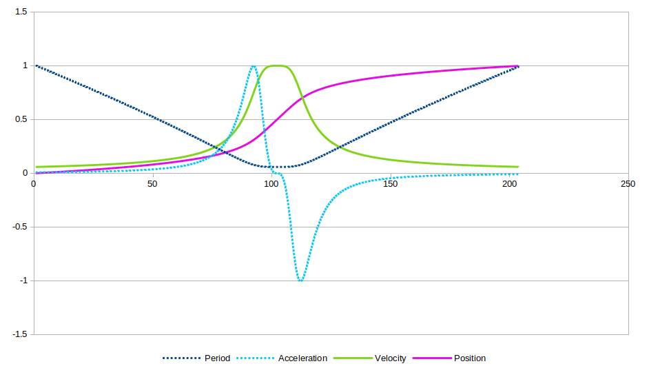
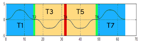
The key insight from the paper is that you can deal with the seven sections separately (during which the displacement monotonically increases):

T1: +jerk,    acceleration ramp, velocity climb
T2: jerk = 0, acceleration max,  velocity climb
T3: -jerk,    deceleration ramp, velocity climb
T4: jerk = 0, acceleration = 0,  velocity max
T5: -jerk,    deceleration ramp, velocity fall
T6: jerk = 0, acceleration -max, velocity fall
T7: +jerk,    acceleration ramp, velocity fall

If you’re willing to use a lookup table, all you really need to capture is periods T1 through T3.

For T4 you can hold at your favorite max speed for as long as you like (velocity, acceleration, and jerk will all still be continuous). You could also safely hold on T2 and T6, but I’d rather reach peak velocity as soon as possible.

Then, T5 through T7 are just the mirror image of T1-T3.

Because I’m not doing any math on the microcontroller–instead, just walking through the delay lookup table array–it does require that the move you’re making has at least as many steps as 2x the velocity ramp. So, for my preferred micro-stepping, I just tuned the length of the T1-T3 lookup table until it was a little under half a frame’s worth of movement. It may dwell at max velocity (T4) for a few extra milliseconds before it starts ramping down, but everything remains very smooth.

On the microcontroller, the whole table ended up compact enough that it can be shown here, inline:

static constexpr u16 move428[214] PROGMEM {
  250,250,250,250,250,250,250,250,250,250,250,250,250,250,250,250,250,250,250,249,249,249,
  249,249,249,249,248,248,248,247,247,247,246,246,245,245,244,244,243,243,242,241,240,240,
  239,238,237,236,235,234,233,232,231,229,228,227,225,224,223,221,220,218,217,215,214,212,
  211,209,207,206,204,202,201,199,197,196,194,192,190,189,187,185,184,182,180,179,177,175,
  174,172,170,169,167,166,164,163,161,160,158,157,155,154,152,151,150,148,147,146,144,143,
  142,141,139,138,137,136,135,134,133,132,131,130,128,127,127,126,125,124,123,122,121,120,
  119,118,117,117,116,115,114,113,113,112,111,110,110,109,108,108,107,106,106,105,104,104,
  103,102,102,101,101,100,100,99,99,98,98,97,97,96,96,96,95,95,94,94,94,93,93,93,92,92,92,
  91,91,91,91,90,90,90,90,89,89,89,89,89,88,88,88,88,88,88,88,87,87,87,87,87,87,87,87,87,87,87,87,86
};

Since my table ended up 214 entries long for the initial acceleration ramp, I always need to ask for a move at least 2 x 214 steps long: half for the acceleration, half for the deceleration. (Otherwise the code falls back to a simple, fixed-delay move… which you can hear as a very different kind of stepping sound from across the room, hehe.)

So if you ask for, say, a 500 step move, it will walk through the delay table for the first 214 steps, use the final value in the table for (totalSteps - 2 * 214) = 72 consecutive steps, then walk backward through the table for the final 214 steps.

It’s such a simple scheme that you end up with the minimum-length move limitation, but being able to generate the table and implement the lookup so easily, it was worth it. The math’y code was a lot worse during my early prototyping, but once I recognized all the symmetry, I ended up with the longest (only?) formulas in my code being the first and third entries from equation (1) in the paper:

double T1(double t) { return  jmax * sin2(k * (t -  0)); }
double T3(double t) { return -jmax * sin2(k * (t - t2)); }

After initially trying to implement the rest of the paper and deciding things were beginning to spiral out of control for my poor little Arduino, I took the simple route. It sounds like you made it farther than I did! I’m curious to hear your results.

@npiegdon Thanks for sharing the insights of how you went about it, especially the key insights.

Understood.

Farther yes, but not farther in the paper :slight_smile:

In my present implementation -linear speed ramp (trapezoid)- an alternative to the fixed-delay is to truncate the trapezoid when the number of steps is below the minimum. The up ramp is 1/4, the top is 2/4, and the down ramp is 1/4 of the steps. When the minimum is exceeded, the top corresponds to the minimum period between steps, and the flat top is expanded when the number of steps exceeds the minimum (I believe this part is similar to yours). But when the number of steps requested is below the minimum, the 1/4 up ramp will only climb up to the corresponding period (not achieving the minimum step) top at that step time for the 2/4 of the steps, and then down ramp back-tracing the same periods used on the on ramp… in virtual silence.

Since I have the ability to select the micro-stepping by code, it would have required 8 look-up tables… For the implementation of the linear speed ramp (current method) here is a key insight.

As you may recall, the Atmel paper provides an approximation, where the first two terms of the series t0 and t1 are different, and then t2 up to tn can be calculated starting with tn-1.

             for (int n = 0; n <= n_delays_up; n++) {
                    switch (n)
                        {
                        case 0:
                            delay_tn = TMC_Motor->tmc_delay_t0;
                            break;
                        case 1:
                            delay_tn = TMC_Motor->tmc_delay_t0 * 0.676;
                            break;
                        default:
                            delay_tn = delay_tlast - (2.0 * delay_tlast / (4.0 * (double) (n) + 1.0));
                        }
                    delay_tlast = delay_tn;

So the key to simplify the puzzle is to figure what tmc_delay_0 would lead to the desired minimum period at the top of the trapezoid. As you did, I played with the parameters in a spreadsheet. With the above algorithm if one provides the constant tmc_delay_0 for each micro-stepping setting, the subsequent periods (t1 to tn) are calculated (keep in mind that I am using the PICO at 125MHz).

//    const double delay_t0 [9] = {1920.163177, 2715.838942, 3841.675937, 5435.494026, 7694.139595, 10901.466701, 15474.296558, 22045.167574, 31627.861259}; // Microsteps 256, 128, 64, 32, 16, 8, 4, 2, 1

In summary, instead of a look-up table for every step period, the look-up table provides the t0 for each micro-stepping setting. This works very well, but… once you make the code fool-film-proof they come up with a better fool-film version :laughing:

Will keep you posted. I will play a bit more with the numbers and then code the speed-sigmoid to compare it with the speed-trapezoid.

Thanks again for sharing your insight.

This is a good idea, especially for the trapezoid case. For whatever reason at the time, for shorter-than-table moves I decided that skipping the rest of the acceleration ramp and switching right to the mirrored deceleration–which violates all the continuity guarantees–would have been throwing the baby out with the bathwater. But… then I chose to fall back to a fixed-delay linear move instead, which (only thinking about it now :sweat_smile: ) is worse in every way!

I probably should have done the same as your trapezoid code (despite the loss of continuity) and saved myself a little vibration on short moves and a case in the code. Oh well, hehe.

All of that aside, it looks like you found some nice implementation short cuts for doing it right on the Pico. (Looking at the specs again, I suppose you’ve got a bit more headroom on that device than I do on this Arduino Mega. :laughing: )

1 Like