I just wanted to share what I’ve been working on.
It’s a real mix of many designs i’ve seen, but It’s still evolving - this has 3D printed bits drilled and bolted on with minimal planning!
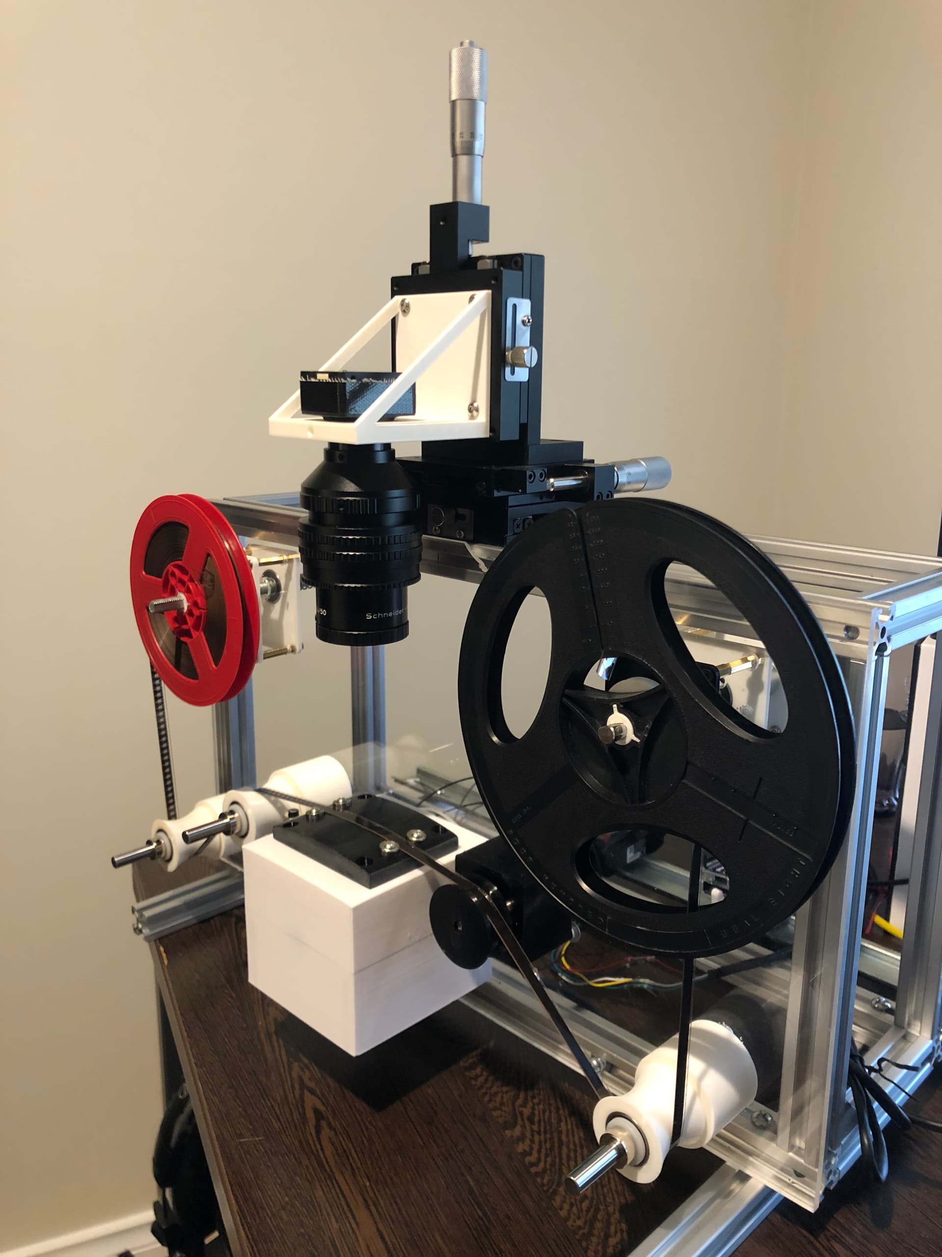
At the moment it will be a single gearbox motor on the take up, with a friction drive on the supply.
Future build will hopefully have a motor on both supply and take up, and a dancer arm for the PID feedback.
light source is diffused in a sphere printed as a square for easy mounting.
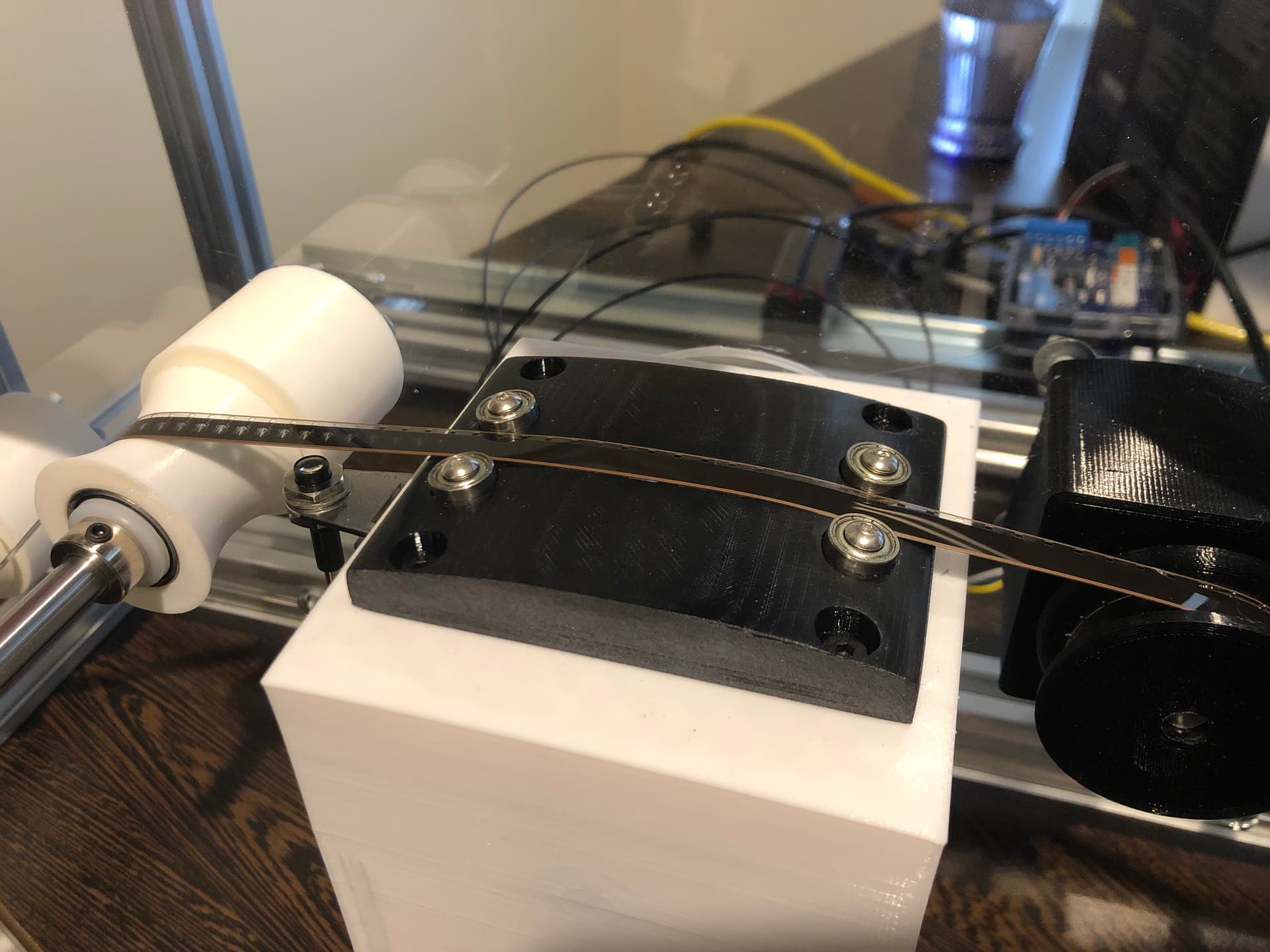
The gate is inspired by the blackmagic cintel, where the gate forms the top of the sphere to get the film as close to the diffused light as possible.
The bearings are fixed at 8mm apart, but I’d like to have two on one side adjustable with a set screw or light spring to hold side tension on the film edge to handle variations in film width.
The gate plate is large enough to make a 16mm version too.
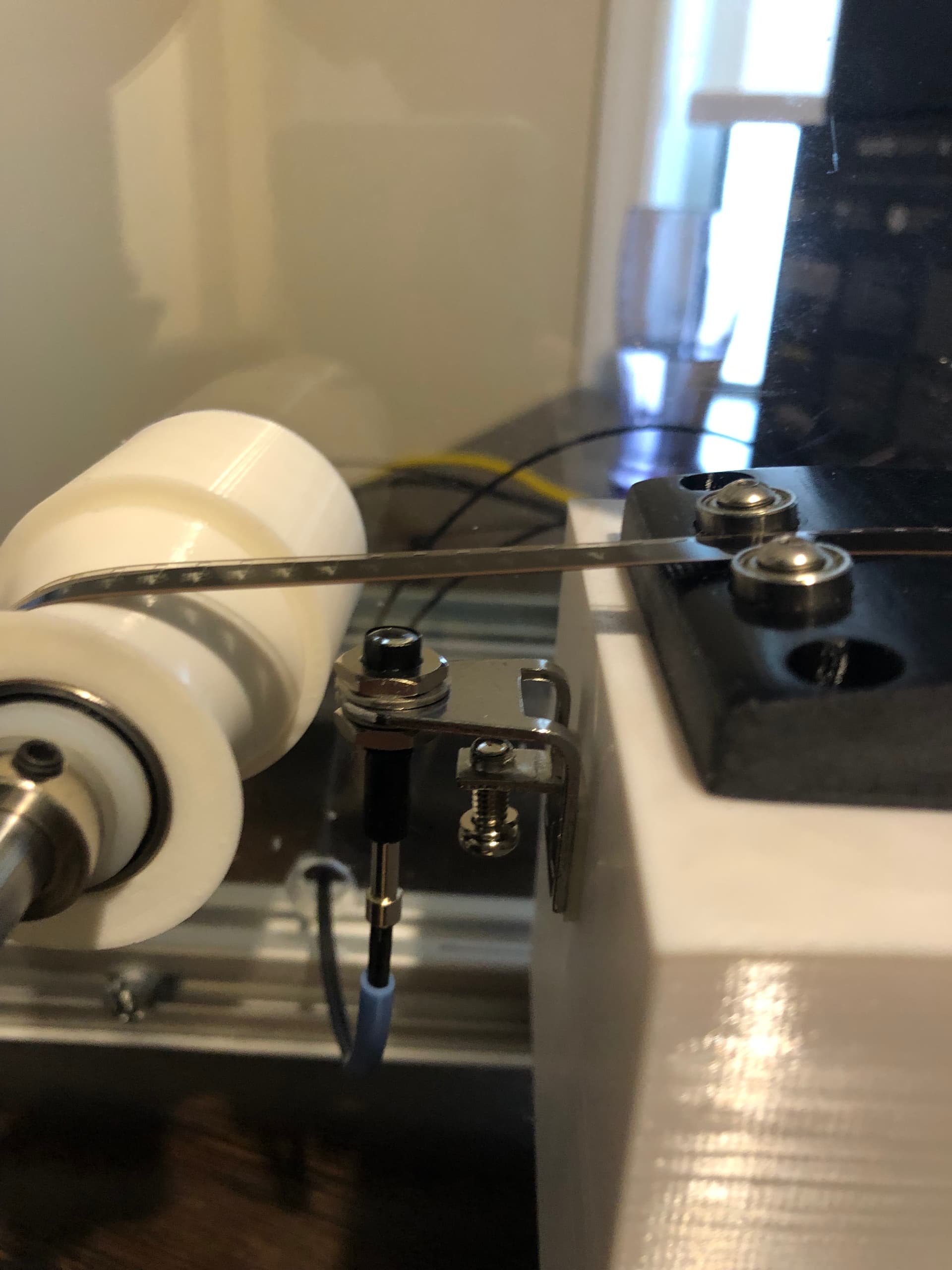
I’m using a keyence sensor for the perforations.
The camera is the 3mp FLIR chameleon I bought 2nd hand.
It can also handle strobing the LED for the light source via a mosfet when the exposure is active.
It’s mounted on a eBay 3 axis linear slide which is actually really nice. Very solid!
I’ve only just got to where I am with hardware, so now I will work on getting the motor speed controlled to a constant 18fps or similar.
There is a rotary encoder on the RHS of the gate, I might use that for film speed, or just the pulse data from the keyence sensor.
This looks like a great build! I like the simplicity of it and how you’ve managed to include a lot of the things we have been discussing here on the forums.
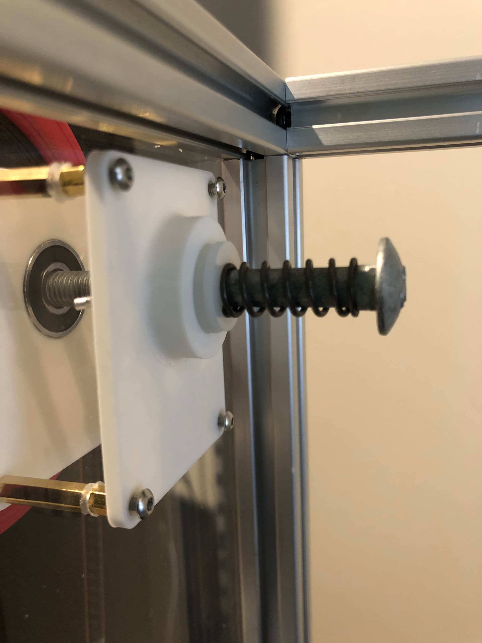
What is the spring-loaded bolt doing? Is it a type of friction mechanism for the feed reel?
How are you maintaining tension and/or feedback to the reel motors?
Thanks Matthew, it would be good to see a few more people give the continuous motion scanners a go. It just needs a brighter light at global shutter.
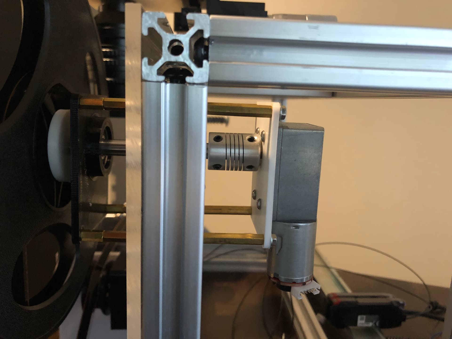
The bolt is an 8mm diameter one I had lying around. It’s worked well for the feed side to create a bit of a friction/slip clutch. There’s a lock nut on the front of it and a nylon washer, so the spring being compressed is pushing the washers against the 3D printed face to create some friction. The tighter I squash it, the more is applied.
I ground a flat spot on the bolt to allow locking the reel onto it to prevent free spinning.
I don’t have any tension control yet, it’s really just what I set with the spring, but tension would change as the reel fills/empties.
In the next build I’ll try add another motor on the supply, along with a dancer arm for some tension and a PID loop to control the feed and take up speeds. Not sure how well it will work!
In the past I had tried a similar approach. For supply- and take-up-reel I just used an DC motor and coupled it with a rubber belt from an old cassette deck. I ran the feeder motor in reverse adjusted the current so it can be pulled into the opposite direction.
For the take-up-reel I adjusted the current so It just had enough strength.
That part worked fine. I had issues with focusing and keeping every frame in the same plane.
My idea was to take 5 frames at once and than crop them later on.
The reason for that was to minimize wear on the DSLR and to have fewer stop-and-go actions.
(or a modulated movement - slow down, when taking picture, then speed up again - all to reduce stress on film)
For now I gave up on this project because I under estimated the projection distortion you get from the frame in the center to the outer frames.
Your input encourages me to continue with my initial setup. Right now I am working with modified projector.
Would if be possible that you share your stl files with us.
Thank you very much
Hi @Ral-Film, after working with small format for a while (8mm/S8), given the optical tolerances is hard to do more than one frame at the time, specially if you are looking for a meaningful resolution (HD and above).
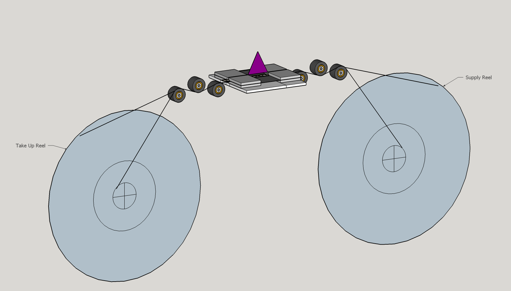
I’ve sketched this transport, but have not build it. The idea was to use steppers to directly control the take-up and pickup reels. One of the rollers can be the tension arm. I’m not a mechanical engineer but my goal was to make the path as simple and smooth as possible. I did test a 3D printer roller with bearings and the size is perfect for 8mm film. Needless to say that the magic for this approach would be using a micro stepper driver and the software to control the stepper (if using stepper motors), but the transport may work well with DC motors too.
Thanks everyone. I’ve uploaded my lighting block and film gate if anyone wants to try printing it to get some ideas. Please note it’s not a final design, the block will probably be redesigned to hold the heatsink better, this is just a press fit for a pin fin heatsink for testing.
I used M3 bolts to mount it together, with M3 heatset inserts.
The bearings are 3mm ID, and 10mm OD. I got them from RScomponents here in Australia.