I’m currently in the process of building my own 35 mm-scanner from an existing projector. Here are a few specs:
Projector: Kinoton FP 30 D
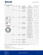
Sensor: FLIR Blackfly S BFS-U3-70S7C-C
Lens: Schneider Componon-S 2.8/50 mm
Light-Source: Self-build from a YUJI High CRI 95+ COB LED
Software for capturing: Spinnaker / SpinView
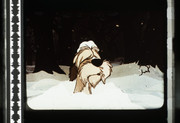
The build is in an early stage so far, but I already managed to capture some first shots. They’re over-exposed due to some wrong Gamma-settings, but I was very happy with them for a first start though:
The next step is to get the sensor triggered so it knows when a frame is in front of the lens and when it has to take a picture. I’m using a Honeywell SS443A Hall Effect Sensor and a Neodymium-magnet, but I’m currently a bit lost with how to connect it.
This is what the Installation Guide says:
So if I get it right I have to connect the red wire to the Hall Effect Sensor, but I have no idea if it’s just the red one or anything else and if there are resistors necessary. My knowledge with this is extremely limited and I don’t want to damage the camera with over-voltage or something just because I connected it wrong to the Hall Effect Sensor.
Can anyone here please help me to get it connected the correct way?
You will need three wires to connect to the GPIO cable. Vcc (power from the sensor circuit), GND, and the output of the hall effect sensor that will go HIGH whenever you want the camera to be triggered.
Note, if the camera is powered via the USB cable, you do NOT need the VCC wire.
I haven’t done this yet myself, but this is my best guess after taking a look at the image you posted.
Vcc → Green (if needed)
GND → Brown
Sensor output → Red
It also seems like you need a resistor according to this page, specifically a 1K. It should (I think?) go in between the brown wire and your circuit’s GND connection.
Hopefully someone smarter will correct me if I’m wrong.
The camera itself is powered through USB, but I’m not sure about the sensor. If I’m getting this right there are only 3.3 V that go through the red cable, but according to these specs for the sensor it needs 3.8 V to work. Or am I mixing something up here?
I believe that Matt has it right that a pull-up resistor is required on the sensor output; power and ground connected too.
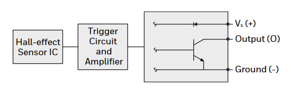
The SS443A is a unipolar sensor with an open collector output. All of the typical circuits shown in the spec sheet have a pull-up; that’s the way open collector outputs work. From what I could determine on the camera specs (not at all familiar with Flir) inputs also require pull-ups. You only need a pull-up in one place. A 1K seems to be the suggested. I assume there is some configuration process for the camera where it is set to use a specific input as the shutter trigger.
OK, so I need to connect the green, brown and red cables to the SS443A and a 1K pullup-resistor has to be put between the brown cable (ground) and the SS443A?
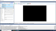
As for the configuration process: There are options for this in SpinView. Here’s the window for GPIO:
The settings written italic are the options I’d assume would be correct for the setup. I just have no clue about what to set for Trigger Activation.
As for the Line-settings they can be set for each line individually if I’m getting it right. But I don’t know what exactly would be the correct setting for each line.
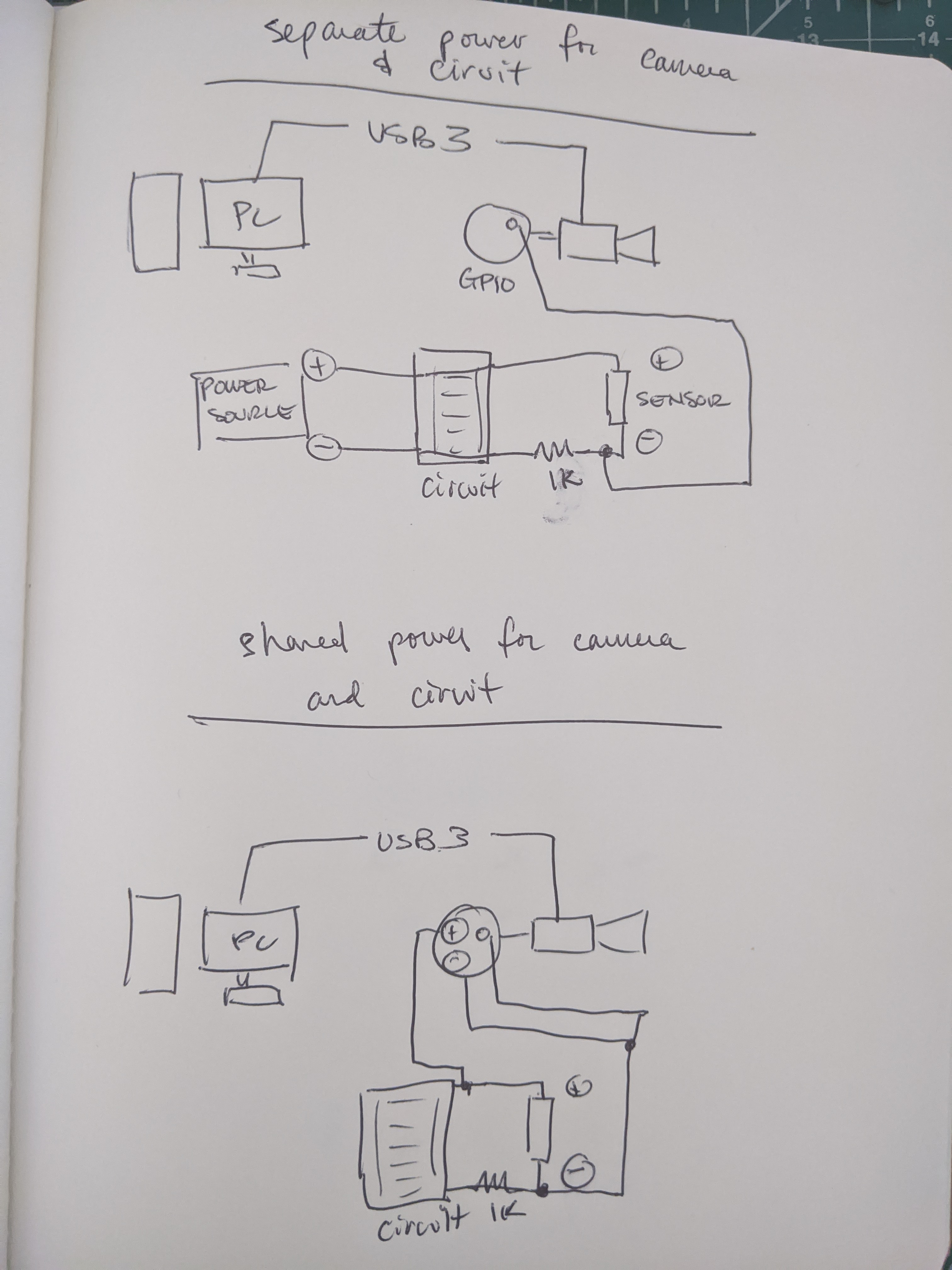
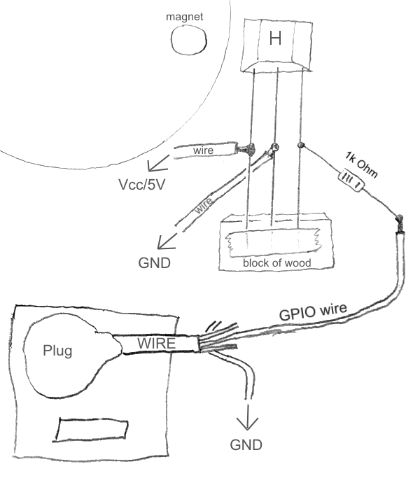
S0rry for the late reply @Doc. Hope you’ve been able to get something working. In case you haven’t, I drew up a sketch of how things could be connected, with two different options. Take into consideration that I’m usually wrong about these things until I try it, fail, and try something new
As for the software settings, maybe ask @johnarthurkelly if he can document what settings he has used successfully in the past.
No problem, haven’t done anything yet, so it’s not too late for further suggestions.
Thanks for the sketch! I’d say using the power from the camera for the sensor as well would be my prefered version. Unfortunately I’m really bad with everything that has to do something with physics, so I have to ask again if I got this correctly:
So (from left to right) the pins on the sensor should be connected with the brown, the red and the green wire if your theory is correct? And the pullup-resistor has to be put between the brown connection as you mentioned before?
My only fear that keeps me from just trying it out is that I don’t want to damage the camera with over-voltage or something, so sorry that I’m asking so many questions.
@Doc That’s a pretty great projector to be using, I always love working with them.
I’m not sure of your sensor set-up and if that will work or not but if you can get a pulse on the input, these are the setting I use to make SpinView capture frames.
If your using the Red wire, on the pin-out diagram that is listed as Line 2 which is what you need to set in SpinView. To set up the input you use Line Selector and select Line2. Then you set the Line Mode to Input.
Then the Trigger Source is set to Line2, and Trigger Activation, I use RisingEdge so it triggers at the start of the pulse I give it.
To set up the capture you should set Trigger Source to Line2, Trigger Selector to Frame Start, and Trigger Mode to On. Then the capturing needs to be done in the Record pop-up menu.
Thanks for that information about the settings in SpinView @The_Projectionist!
That should indeed be very helpful.
Does anything have to be set for “Line Source” as well or can that stay “Off”? And does there also have to be a setting for Line 3 (the green wire) to get the SS443A powered (Line Mode to “Output” or anything) or can it just stay as it is by default?
I think the Line Source outputs are just logic type outputs @Doc
As for power out of the camera, I’m not sure. I’m running the camera trigger and sensors through an arduino.
“Idiot level” for people that have never seen an electrical schematic, but more importantly practical.
I think @matthewepler had the 1k Ohm resistor on the wrong wire. Of course it won’t hurt to put a resistor on the GND wire whether you really need it or not. I would tape it as shown to a small block of wood, or a piece of lego, something like that so you can move it around and find the optimal distance from the magnet, and then once you’ve found it you can glue it into place. I don’t think you want to move the magnet, I think that would go on the outside of the rotating gear and you move the hall effect sensor to the sweet spot.
You can solder straight to camera pins, but if you have a plug like in the diagram it would be more optimal. For example it makes it more modular such that if/when Doc’s group decide to build a 16mm scanner as well then they’ll want to be able to move their camera from one unit to the other easily.
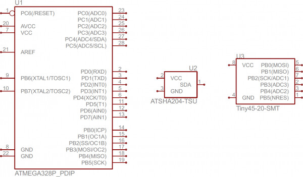
Oh the other correction, Doc was confused by the circuit diagram on page 2:
So just to explain this - a circuit diagram doesn’t necessarily show pinout in the correct order. In fact sometimes you’ll see a big chip with all the pins labelled in what will look like a random archaic fashion, but this is to simplify the circuit diagram - for example they’ll put GND and +Vcc pins next to each other especially if they’re externally connected, or if they’re internally connected as is the case above. For example:
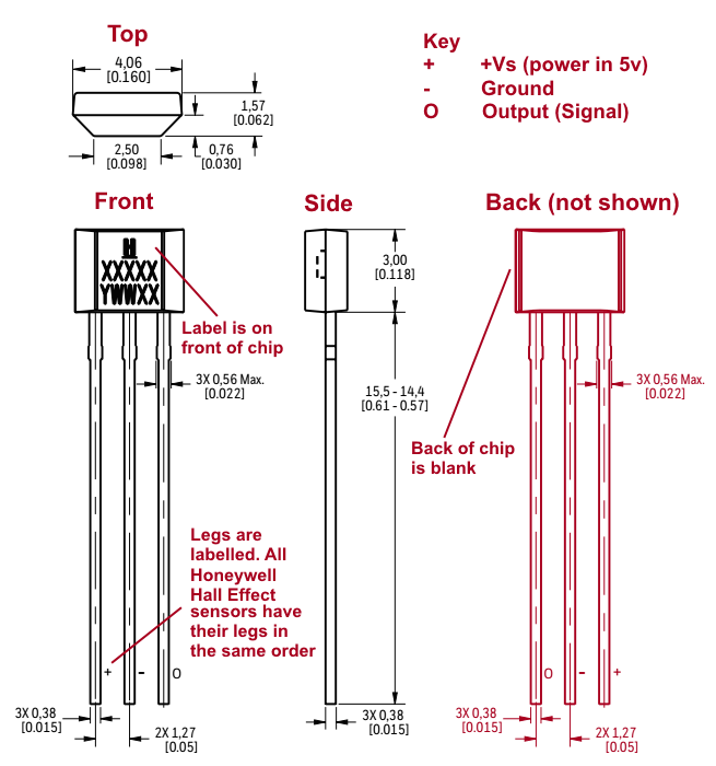
As you can see in those diagrams the pins are not in the physical order they would be found on a real chip. So in the case of the hall-effect sensor the correct order is shown here (from page 6 of the specs PDF with notation):
The naming conventions are a little odd, but do note that the Key I included is on page 2 of the PDF (the circuit diagram Doc posted) so there can really be no confusion. Also the legs will follow a common standard, so I’m sure if I was to look at other brand hall effect sensors they would be in the same order as this one (Input, Ground, Output) and I/G/O appears to be a common standard for three leg chips like say a standard voltage regulator chip. You can tell the front and the back apart by the fact that the front has a label on it, as is shown in the diagram, I’ve drawn in how the back would look but specification documents are never going to bother including the reverse of a chip because that’s just duplicating information you already have.
Now the next step would be attaching the opal glass-diffusor and getting the settings etc. adjusted. And then there’s also the problem with the blurred left edges on the audio track which still gives me some headaches. I hope closing the lens aperture a little will help to get rid of this. Did someone here have a similar issue in the past and maybe knows what could be the cause of this?
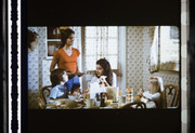
So now that the trigger is working I finally tried to get some first material scanned. Worked fine and the results look good to me when they’re downscaled to 1080p, but looking at them in full resolution I still feel that this isn’t the end of the line.
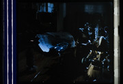
Here are a few screenshots from the test-scan of a trailer-reel:
What bothers me the most is the sharpness-issue. One side of the audio-tracks always looks quite blurry, the other side looks better - though I think it could also be sharper. Similar effects appear when something’s written on screen. Is this just how it is with the Componon-S or are there any tricks that’ll help to improve it? I’ve seen some screens from others here, who are also using the Componon-S on a BFS and their results looked better to me.
It also seems that the diffusion of the light doesn’t work perfectly even. It looks ok on the screens, but if you crank up the exposure you can see a round glow on the left side and a bigger glow coming from the right side. It can be best seen if you use the picture from the leader or the other black frame.
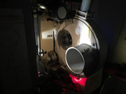
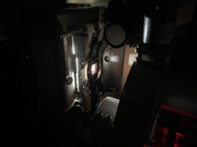
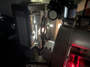
Here are a few pics from how the camera is pointing at the gate:
The shutter on the lens is fully open - would it help to close it down and if so: Would you rather shoot more light at the film or increase the exposure time in SpinView to compensate the closure? Sorry if this sounds like another dumb question, but I’m also not an expert on photography.
If you need any further information please let me know and I’ll try to provide that information.
Thanks in advance for your suggestions!
I assume that you are referring to the aperture of the lens. According to many users this lens is best when stopped down about two stops. Scheider 50mm f/2.8 enlarging lens review.
Also check whether the lens sits perfectly perpendicular to the film so the sensor is parallel to the film.
What is the exposure time you used?. Are you running the projector at 24 fps?
Thanks for your reply!
Correct, it‘s currently working at f/2.8 and the projector runs at 24 FPS.
The exposure time is currently set to 2998. I wasn‘t sure whether it‘s better to increase the exposure time or the light itself. Do you think it‘d be better to use a higher exposure time and a lower amount of actual light to maybe also get rid of the glow?
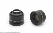
EDIT: I just recognized there are different versions of the Componon-S 2.8 / 50 mm around. The one that I got is the older version with the all metal barrel:
I also read that mounting the lens in reverse might help. Right now it’s mounted the “correct” way. Do you think I should get a reverse adapter to get better results?